

Today's post is also related to arduino software but, the difference is that, in previous post we learn How to use the arduino software, What are the function keys of this software and Where to write the code(sketch) and after writing the sketch, how it is debugged. Now in today's post which is ' Getting started with Arduino Programming', we will see How a Code is written in Arduino software? What are the built-in functions of Arduino software? How comments are made in sketch? What are the main loops, used in Arduino programming? How pin selection is done in Arduino software? How Digital pins are controlled, which are embeded on Arduino board? To explain this whole software in detail, i have divided this tutorial into major parts and also their sub-parts. Above was a little introduction about what actually we are going to learn in this post. Now without wasting any further time on introduction (as i will be explaining each and every step in below tutorial) i think now we should move towards the actual learning of the Arduino software to use it for programming.
You should also read:
1- How to make Comments in Arduino Programming
- I hope that you are a beginner and i will start to elaborate the soaftware from very beginning.
- First of all open your Arduino software. Go to file menu, a new window will open, from there click on the Examples and then go the Basics.
- After clicking on basics a third new window will open and it will be showing all the basic Arduino built-in basic functions.
- If you haven't bought your Arduino UNO yet, then you can buy it from this reliable source:
- For beginners the function named as blink is very useful, so i will also teach you from this basic level tutorial.
- When you will click on 'blink' option then, a new window will open, which is shown in the image given below:

- In the above shown image you can see that we have opened a basic level example from built in Arduino software.
- Now under this heading title, i will explain how to make comments in Arduino programming?
- This is in fact the syntax to make comments in your sketch.The above code is of very basic level and it elaborates how to blink a single led by using Arduino board.
- If you look closely in the above image then you will see that some words are written in the start of the sketch and these words are encloses in these signs " /* ..........*/ ".
- An other way to add the comments is to write " // .........." before every line in your sketch.
- When you will do that before any particular line then, that line will become green and it will no longer have any effect in the sketch.
- There is also a little difference in these both techniques of making comments.
- First technique is used at that place where we have to write 3 or 4 lines together, or a large paragraph is to introduced in the sketch to make the user understand the sketch. We don't have make every line comments one by one. So, this method of making comments gives us ease.
- While the second technique is used at that place, where we have to make comments in a single line.
- Both these techniques have there own purposes and are used at that place where, we wish to use them.
2- Main Loops In Arduino Programming
- Now the next step in learning Arduino programming is to learn about the main loops, which are used in Arduino programming.
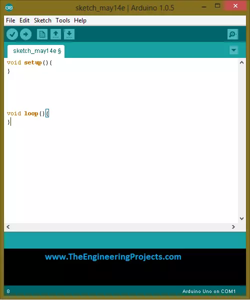
- To see what are the main loops, you simply go to the file menu and click on the new button and a second new window will open, which is shown in the image given below:
- Above image is showing the main loops, which are used in Arduino software while programming.
- The first loop is 'void setup' and the second loop is 'void loop'.
- The syntax to write these both loops is also shown in the above image. But you should don't worry about the syntax of these loops because the good news is that the software it-self generated the syntax, when you open a new file to write the sketch.
- Void setup is the first and the main loop while programming in Arduino. It is used for initialization and for configuration of constant values.
- For example while writing a sketch if you are gonna need some constant values in your code then, it is necessary that you must initialize them first in this loop.
- If you didn't initialize those constants first then, code will not execute properly and it will generate error.
- The other main loop which is used while using programming in Arduino is "void loop", as you can also see it from the above given image.
- An important thing to note here is that the compiler checks each and every line one by one in steps.
- The compiler moves from top to bottom and in the first step, it will read every line of the " void setup() " and then it comes to the " void loop() " and it reads/compiles every line written in this portion.
- So from the above given info, we can conclude that ' void loop() ' is similar to ' while(1) ' loop, which is in fact an infinite loop.
3- Pin Mode Selection in Arduino Programming
- In the above two portions of the today's tutorial we have seen, How to make comments while doing programming in Arduino software and secondly What are the main loop being used in Arduino programming.
- Now we are going to the third stage which is Pin Mode selection in Arduino programming.
- If you are aware of the other micro controllers like ATmel series, PIC or AVR, then you may also know that the pin configuration of these micro controllers are fixed.
- Which means you have pre-decided input and output pins of the micro controller. Those micro controllers have definite pins for inputs and also for outputs and they can only be used for that specific purpose.
- For example if a micro controller have a input port then all the pins on that port will be used to receive data and you can't use them to send data.
- While working with Arduino micro controller gives us a flexibility that every I/O pin available on the board (except for some definite pins like VCC,GND, etc) can be used as input or output pin.
- For example if we wish to connect a led at the pin#2 of our Arduino board, which means we are going to make this pin#2 as a output pin.
- For Arduino board we will send data to this pin through our code, which means we have made this pin as an output pin.
- The syntax to write command to do this function is:
pinMode (2 , OUTPUT)
- By writing this command in the code, we have made pin#2 as a output pin.
- And if we connect some kind of sensor at this port and we have to take the value of that sensor as an input then, we will have to make pin#2 as an input pin.
- In order to make the same pin as an input pin, we will have to write the command in the following syntax:
pinMode (2 , INPUT)
- By writing this command, Arduino board will automatically made the pin#2 as an output pin.
- Pull-up criteria is also very important in writing any commands for Arduino board.
- There is only one problem with all the Arduino boards that, we whenever an un-initialized pin is used in our code then the Arduino board send some garbage value to that particular pin.
- To overcome this problem we have to set some particular value for each and every pin. and we ahve to define state of every pin that either it is HIGH or LOW.
- For example we can say that the function of pin#3 is that GND is always connected to that pin and if ground is not available at any case then we will send +5V to that pin to keep that pin in a particular position.
- The Arduino board command for pull-up purpose is:
pinMode(2 , INPUT_PULLUP);
- This command will automatically decide the particular value of every pin.
4- Digital Pins Controlling in Arduino Programming
- Now the fourth part of the today's tutorial in learning of Arduino Programming is How digital pins are controlled while coding in Arduino.
- Arduino board is a multi purpose micro controller and it is also capable of sending and receiving data from Digital as well as Analogue data.
- It is our choice to make every pin as an input or output pin and similarly either it has to send or receive Digital data or it has to send or receive analogue data.
I/P Digital Pins:
- For example, i wish to make my pin#2 as an Digital input pin, which means it will read digital data from some external source.
- The command to do this function is given below as:
digitalRead(2); boolean sensor=digitalRead(2);
- The first command is teeling the Arduino compiler to make pin#2 as a digital pin and the compiler will take Digital input data from that pin.
- While the second command i have written is to save the command in a variable.
- In this command i have introduced a datatype named as 'boolean' . You can also change the name of this datatype.
- And the name of the variable is 'sensor'. I have kept the name 'sensor' and you can also change this name according to your own choice.
O/P Digital Pins:
- Next if you wish to make these pins as an output pins then we can also do that.
- Suppose now if you want to make your pin#2 as an output pin and you wish to send data to this pin or you want to define the state of this pin then the commands, which you will write are:
digitalWrite(2,HIGH); digitalWrite(2,LOW);
- In the syntax of writing the command, we will first write no of the pin and then we write it's state.
- The first command is showing that we are writing digital data on our pin#2 and we are going to set it in HIGH/ON state.
- The second command shows that we are going to set the pin#2 in OFF state.
5- Analogue pins controlling in arduino programming
- In this section of the tutorial we are going to see how to control the Analogue pins of an Arduino board.
I/P Analog Pins:
- As i have explained above in detail that how we can digitally take or send data using Arduino pins.
- An interesting feature is that Arduino board pins can also be used to send or receive data in an analog pattern.
- Since my heading is to input analog data, to understand this pattern suppose that you are going to read some analog voltage from pin#2 of arduino board.
- In order to do that, the commands which you will write in Arduino software are as:
analogRead(2); int sensor Value = analogRead(2);
- As you can see that the syntax to read Digital and Analog Data is same.
- In first command i am reading the analog data from external source at pin#2 of arduino board.
- In the next command i have stored that data into a variable named "sensor value" .
- After that all the analog data which will appear at pin#2 will be stored in 'sensor value'.
O/P Analog Pins:
- Now if we wish to use the pins of Arduino board as an output pins then it is also very easy and you can also do that by following some simple steps.
- If you wish to use any pin to write data or we can say that you wish to turn a switch ON or OFF then, the syntax will be as:
analogWrite (3,HIGH); analogWrite (3,LOW);
- The first is showing that a switch has been connected at pin#3 and you wish to turn it ON and you will write the first command in Arduino sketch.
- The second command is showing that a switch is already in ON state, which is connected at pin#3 and we wish to turn it OFF then, we will write the second command in our Arduino sketch.
