


So, that was a brief introduction about Stepper Motor and if you wanna read in detail about it then you should read the Wiki Page of Stepper Motor because they have explained each and everything about stepper motor in detail. I would also recommend you to read Stepper Motor Drive Circuit in Proteus ISIS because in this post I have given the basic movement of the stepper motor in detail. Our today's task is stepper motor control using PIC Microcontroller. I have used PIC16F877A for stepper motor control and I have designed the simulation for stepper motor control in Proteus ISIS software. Code written for PIC Microcontroller is designed in MikroC Pro for PIC Compiler. Simulation and Programming code is given below for download but I would recommend you to design it on your own so that you learn most of it. Anyways, let's get started with Stepper Motor Control using PIC Microcontroller.
Stepper Motor Control using PIC Microcontroller
- In this project, I am gonna control the speed angle and direction of the stepper motor using a PIC Microcontroller.
- I will send commands via Serial Terminal and on the basis of these commands, our stepper motor will change its step size as well as direction.
- You can download the stepper motor control simulation and code by clicking the below button:
- Now let's design it in Proteus, first of all, design a circuit as shown in the below figure:
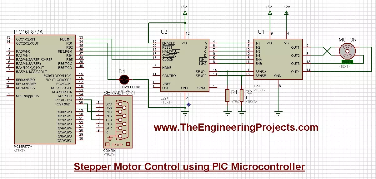
- Now you can see in the above figure that I have used L297 and L298 as stepper motor drivers.
- You can do stepper motor control without these drivers in Proteus software but when you design it in real hardware then these drivers will be required.
- Moreover, I have used the COMPIM which is used for serial control. We will send commands via serial port and the motor will follow the instructions.
- So, now upload the below code in your PIC compiler and get your hex file.
char uart_rd;
void main()
{
  TRISB = 0;
  PORTB =  0;
      UART1_Init(9600);
    Delay_ms(100);
  while(1)
  {
    PORTB.F0 = 1;
    Delay_ms(250);
    PORTB.F0 = 0;
    Delay_ms(250);

    if (UART1_Read() == ('e') ) {

    PORTB.F2 = 0;
    }
    else         {
    PORTB.F2 = 1; }
    if (UART1_Read() == ('a') ) {

    PORTB.F3 = 1;

    }
    else         {
     }
       if (UART1_Read() == ('b') ) {

    PPORTB.F3 = 0;
    }
    else         {
     }

          if (UART1_Read() == ('c') ) {

    PPORTB.F4 = 0;
    }
    else         {
     }
             if (UART1_Read() == ('d') ) {

    PPORTB.F4 = 1;
    }
    else         {
     }

}}
- Now upload the hex file in your PIC Microcontroller and run your simulation, if everything goes fine then you will get results as shown in the below figure:
- Obviously, you can't see the motor running in the above picture but you can see it has moved to some angle.
- In actuality, it will start moving continuously and will stop when you send a command on the Serial terminal.
- The below video will explain the whole project in detail:
So, that's all about stepper motor control. I hope you have liked it and it will help you in some way. In the coming post, I will share the stepper motor control with the Arduino board. So stay tuned and have fun!!! :)
