

This Line Following Robot is not doing any extra feature i.e. turning or rotating back. It will just simply move in the straight line. I have also posted a short video at the botton of this tutorials which will give you better idea of how this robot moves. You should first read this tutorial and design the basic robot and once you are successful in designing the basic Line Following Robot then you should have a look at my recent Project Line following Robotic Waiter in which I have designed a Robotic waiter which follows the line and also take turns on different tables. So, let's get started with Line Following Robot using Arduino.
Line Following Robot using Arduino
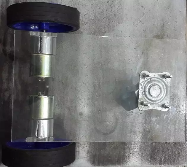
- First of all I have designed the Mechanical model of the robot, which has three wheels on it.
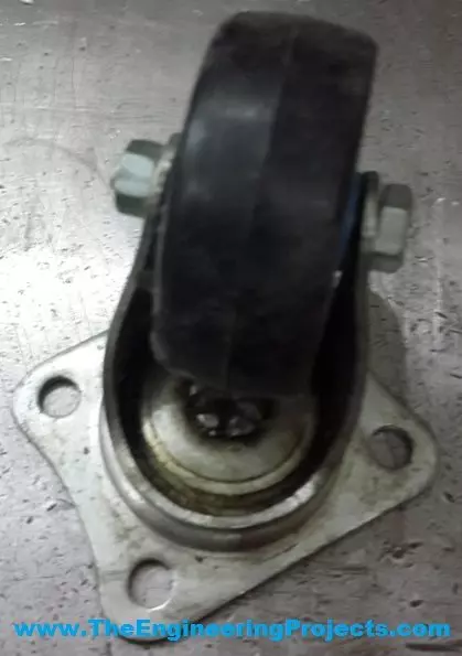
- Its a triangular method in which the motors were attached to the front two wheels and the back wheel is a caster wheel, which is present in the middle of the robot.
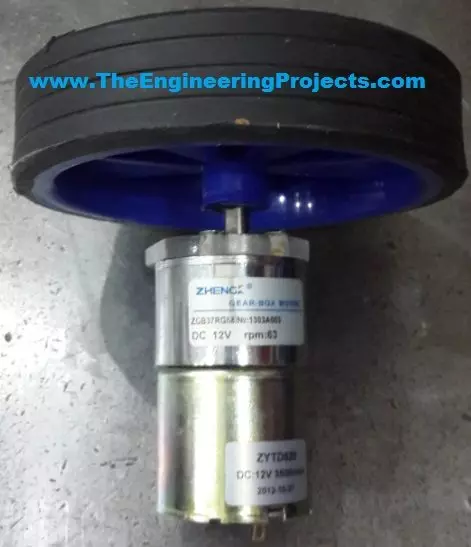
- Here's the image of front wheel coupled with the DC Gear Motor:
- Now let's have a look at the rear caster wheels, shown in below image:
- Finally, I have used Acrylic as the body of the robot.
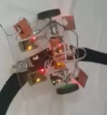
- Here's the assembled version of our Line Following Robot:
- Now that we have the mechanical design of our robot and we have assembled it completely.
- So, now comes the electronics part where we are gonna place the DC Motor Driver Circuits and will also place the IR sensors.
- I have used Arduino board for programming of this Line following Robot.
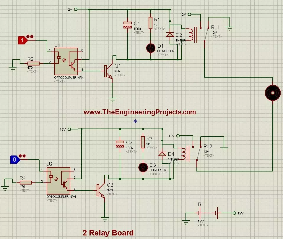
- First of all, I have designed the 2 relay baord for DC motors.
- Its circuit diagram is shown in below figure:
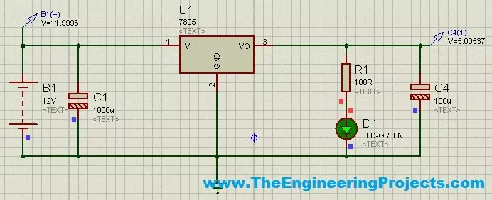
- We also need a voltage divider circuit because we need such a power supply from which we can get 5V, while our source battery is of 12V.
- So, in order to do that I have used 7805 Regulator IC and have designed a simple circuit as shown in below figure:
- Now placing all the components over the Line following Robot, it looked like something as shown in below figure:
- Here's the Arduino code which you need to upload in your Arduino board:
#define motorL1 8
#define motorL2 9
#define motorR1 10
#define motorR2 11

#define PwmLeft 5
#define PwmRight 6

#define SensorR 2
#define SensorL 3
#define Sensor3 A0
#define Sensor4 A1

#define TableA A4
#define TableB A2
#define TableC A5
#define TableD A3

int OriginalSpeed = 200;
int TableCount = 0;
int TableCheck = 0;
int RFCheck = 10;

void setup()
{
  Serial.begin (9600);

  pinMode(motorR1, OUTPUT);
  pinMode(motorR2, OUTPUT);
  pinMode(motorL1, OUTPUT);
  pinMode(motorL2, OUTPUT);

  pinMode(PwmLeft, OUTPUT);
  pinMode(PwmRight, OUTPUT);

  pinMode(SensorL, INPUT);
  pinMode(SensorR, INPUT);
  pinMode(Sensor3, INPUT);
  pinMode(Sensor4, INPUT);

  pinMode(TableA, INPUT);
  pinMode(TableB, INPUT);
  pinMode(TableC, INPUT);
  pinMode(TableD, INPUT);

  MotorsStop();

  analogWrite(PwmLeft, 0);
  analogWrite(PwmRight, 0);
  delay(2000);
 // Serial.println("fghfg");

}

void loop() {
  MotorsForward();
  PIDController();
}

void MotorsBackward()
{
    digitalWrite(motorL1, HIGH);
    digitalWrite(motorL2, LOW);
    digitalWrite(motorR1, HIGH);
    digitalWrite(motorR2, LOW);
}

void MotorsForward()
{
    digitalWrite(motorL1, LOW);
    digitalWrite(motorL2, HIGH);
    digitalWrite(motorR1, LOW);
    digitalWrite(motorR2, HIGH);
}

void MotorsStop()
{
    digitalWrite(motorL1, HIGH);
    digitalWrite(motorL2, HIGH);
    digitalWrite(motorR1, HIGH);
    digitalWrite(motorR2, HIGH);
}

void MotorsLeft()
{
    analogWrite(PwmLeft, 0);
  analogWrite(PwmRight, 0);
    digitalWrite(motorR1, HIGH);
    digitalWrite(motorR2, HIGH);
    digitalWrite(motorL1, LOW);
    digitalWrite(motorL2, HIGH);
}

void MotorsRight()
{
      analogWrite(PwmLeft, 0);
  analogWrite(PwmRight, 0);
    digitalWrite(motorR1, LOW);
    digitalWrite(motorR2, HIGH);
    digitalWrite(motorL1, HIGH);
    digitalWrite(motorL2, HIGH);
}

void Motors180()
{
    analogWrite(PwmLeft, 0);
    analogWrite(PwmRight, 0);
    digitalWrite(motorL1, HIGH);
    digitalWrite(motorL2, LOW);
    digitalWrite(motorR1, LOW);
    digitalWrite(motorR2, HIGH);
}

void PIDController()
{
  if(digitalRead(SensorL) == HIGH){analogWrite(PwmRight, 250);analogWrite(PwmLeft, 0);}
  if(digitalRead(SensorR) == HIGH){analogWrite(PwmLeft, 250);analogWrite(PwmRight,0);}
  if((digitalRead(SensorL) == LOW) && (digitalRead(SensorR) == LOW)){analogWrite(PwmRight, 0);analogWrite(PwmLeft, 0);}
}
- Now that's all, here's the video for Line Following Robot using Arduino which will give you better idea:
