Hello friends! I hope you all will be absolutely fine and having fun. Today, I am going to share my knowledge with all of you about how to make a simple program for DC Motor Direction Control in LabVIEW. In my previous tutorials, I have also worked on DC Motor Direction Control using Arduino. You should go through these tutorials they will be helpful in better understanding of the tutorial DC Motor Direction control using NI LabVIEW. The word DCis basically an abbreviation of Direct current. So, a direct current motor is commonly used motor having two input terminals, one is positive and the other one is negative. If we connect these terminals with the voltage supply the motor will rotate. If you change the polarity then motor will rotate in opposite direction. You should also have a look at Difference between DC & AC Motors to get a better idea about these motors.
DC motor has a lot of applications. You can use it in automation projects, for controlling static as well as mobile robots, in transport system, in pumps,fans,bowers and for industrial use as well. In this tutorial I will work on DC Motor Direction Control using NI LabVIEW. In my previous tutorial, I have done the DC Motor Direction Control in MATLAB and I have used the same hardware but instead of controlling it from NI LabVIEW I have controlled it using MATLAB so you must have a look at that tutorial. Now let's get started with DC Motor Direction Control in LabVIEW.
DC Motor Direction Control in LabVIEW
In this tutorial, I will make a simple program to work on the DC Motor Direction Control in LabVIEW. NI LabVIEW is an amazing software tool specially for the students, because it is very easy to use and understand. So, its a student friendly tool. Before going into the details of this tutorial, you must go through my previous tutorials because I am going to use the same hardware setup and same Arduino source code as well. I will made a simple GUI (Graphical User Interface) in LabVIEW for DCMotor Direction Control in LabVIEW. There will be three different buttons on the GUI for clockwise rotation, counter clockwise rotation and stopping the stepper motor respectively.
You can download the complete SImulation for DC Motor Direction Control using NI LabVIEW here:
Download .rar file, extract it and enjoy the complete simulation for DC Motor Direction Control using NI LabVIEW.
How to Build Complete VI
First of all open NI LabVIEW software on your laptop or PC so that we could design the GUI for DC Motor Direction Control in LabVIEW.
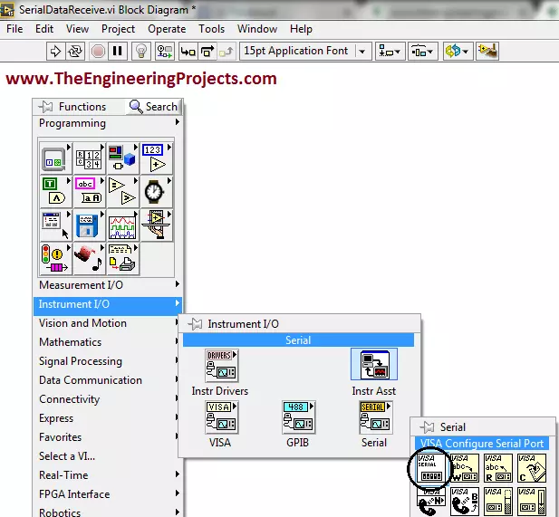
Go to the Block Diagram window and Right Click on it.
Go to Functions-> Instrument I/O-> Serial and you can see different serial blocks like VISA Write, VISA Read, VISA Serial etc.
Choose the encircled VISA Configure Serial Port and place it on the Block Diagram window.
VISA Configure Serial Port block will help us to open the Serial Port before executing the algorithm.
The screen shot of the Block Diagram is shown in the figure below.
Go to the first input terminal of the VISA Configure Serial Port block and go to Create-> Constant.
Above step will be helpful to select the COM port of the Arduino board in order to run the program properly.
Updated Block Diagram window is shown in the figure below.
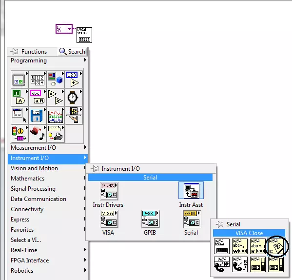
Now go to Functions-> Instrument I/O-> Serial, you can see there different serial blocks.
Choose the encircled VISA Close block and place it on the Block Diagram window.
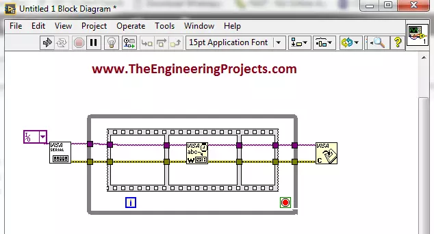
The VISA Close block is shown in the figure below and it will be help in closing the Serial Port if needed.
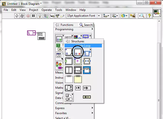
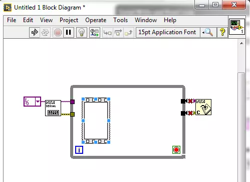
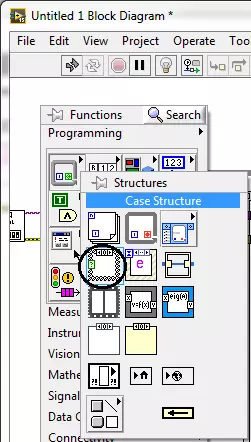
Now, go to the Functions-> Programming-> Structures and you can see the different structures there like For Loop, While Loop, Case Structure etc.
Choose the encircled block as shown i the figure below.
Place all the above blocks in a way shown in the figure below.
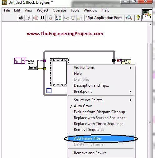
Now, go to the Functions-> Programming-> Structures-> Flat Sequence.
Flat sequence block is encircled and is shown in the figure below.
Put your cursor and go to Add Frame After.
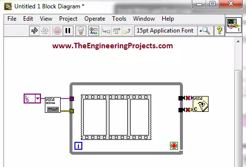
Similarly ad another case after this as shown in the figures below.
Newly added frame is shown in the figure below.
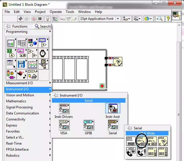
Now, go to Functions-> Instrument I/O-> Serial, you can see different serial blocks there.
Choose the encircled VISA Write Block and place it on the Block diagram window.
The figure shown below elaborates the above steps.
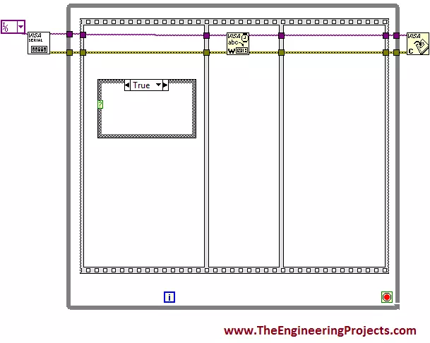
Make the connections as shown in the figure below.
Now, go the Functions-> Programming-> Structures and you can see different types of structures like for loop, while loop, flat sequence etc.
Choose he encircled block as shown in the figure below.
Select the Case Structure block and place it on the block diagram window.
The figure shown below displays the above step.
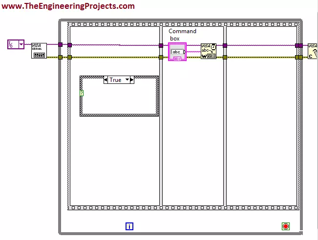
Now, go to the input terminal of the write blockand go to Create-> Control.
Change the name of this block to Command box as shown in the figure below.
The block diagram window is shown in the figure below.
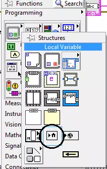
Now, go to Functions-> Programming-> Structures and you can see different structures blocks there.
Choose the encircled block as shown in the figure below.
Select the Local Variable Block and place it on the Front Panel.
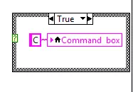
Right click on it and select Command box as shown in the figure below.
Go to the input terminal of this local variable and go to Create-> Constant.
Place C inside that constant.
The figure below elaborates the above step.
The above case structure is for the clock wise rotation of the stepper motor.
Similarly make two further case structures for counter clockwise rotation and stopping the rotation of the stepper motor.
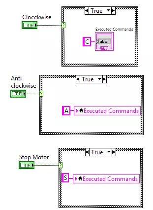
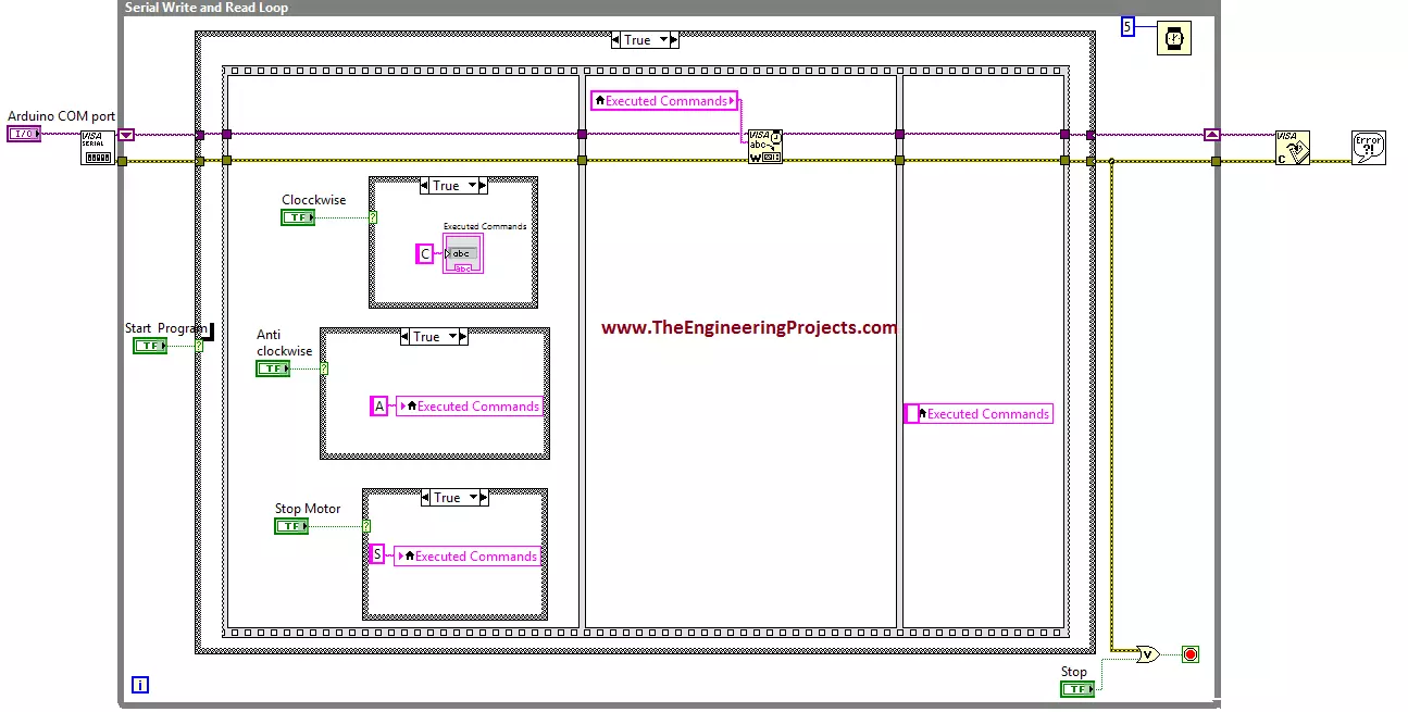
All the three case structures are shown in the figure below.
You can see three different case structures in above figure.
The command box variable having command C will rotate the stepper motor in clockwise direction.
A command box variable having command A will rotate the stepper motor in counter clockwise direction.
The command box variable having command S will stop the rotation of the stepper motor.
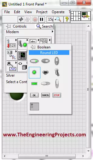
Now, go to the Front Panel and Right Click on it.
Go to Controls-> Modern-> Boolean and you can see there different Boolean blocks.
Choose the encircled block as shown in the figure below.
Select the Round LED block and place it on the front panel.
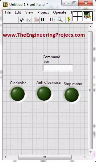
Similarly select two more round LED blocks and place them on the front panel as well.
Change their names from default to Clockwise, Anti clockwise and Stop Motor.
All of the above steps are explained visually in the figure shown below.
The LED shown in the above figure will control the stepper motor on clock wise, counter clock wise direction and will stop the motor as well.
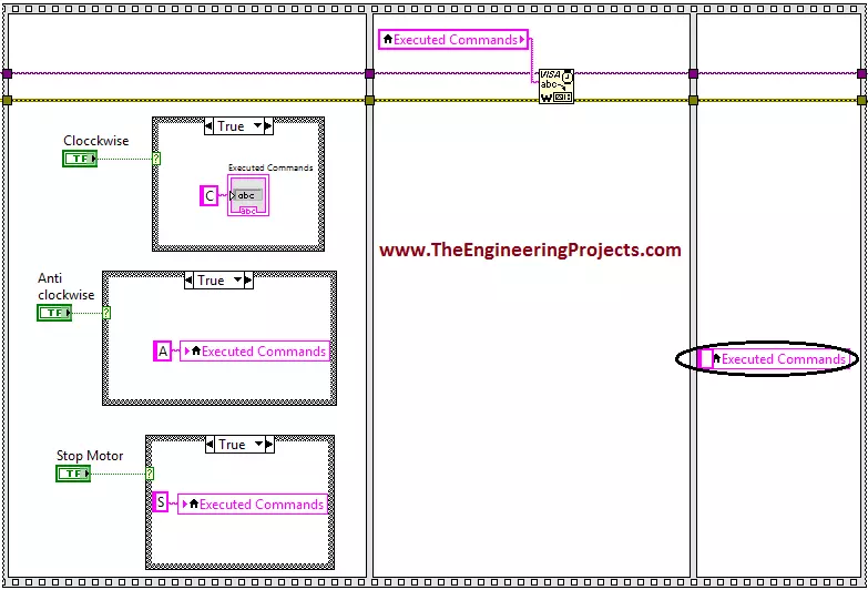
Now go to the block diagram window and connect these blocks as shown in the figure below.
At the end, after sending all the commands we must need to close the serial port so that unnecessary exchange of commands could be avoided.
So I have cleared the all the commands in third frame of the case structure i.e I am sending no commands through the serial port.
This will be helpful in closing the serial port.
The figure show below explains all of the above steps visually.
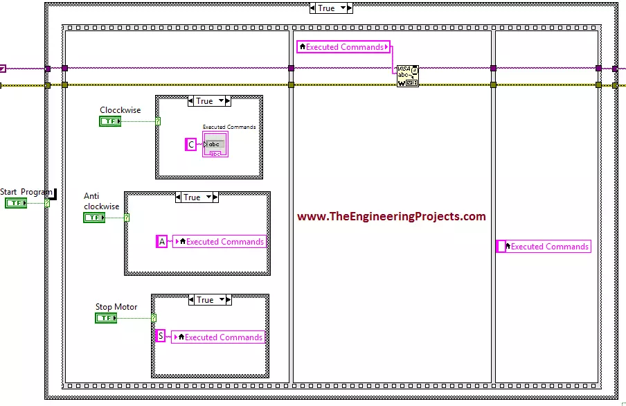
Now add another case structure to start the program when you want so.
The figure below shows the newly added case structure.
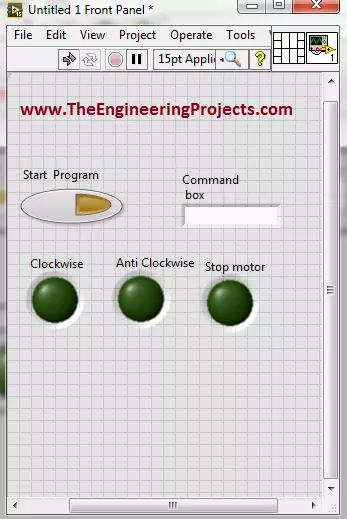
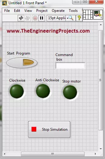
Now, go to the Front Panel, the button encircled in the figure shown below is used to start the program when needed.
Now add a Stop button in order to terminate the program whenever you want so.
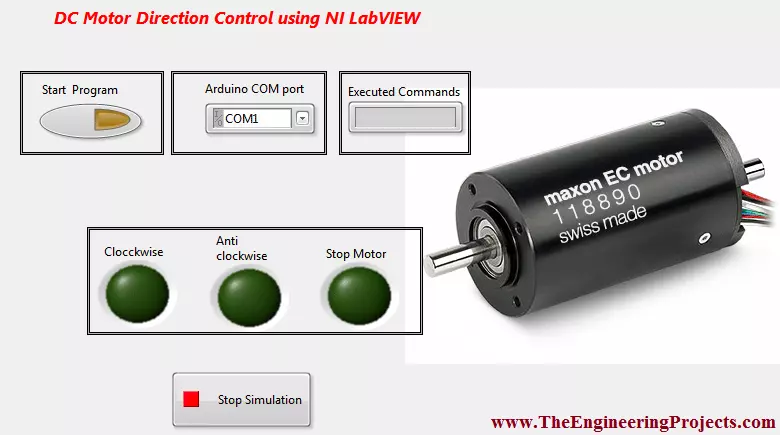
The complete output of the program is shown in the figure below.
A complete NI LabVIEW Virtual Instrument (VI) is shown in the figure below.
Decorated Front Panel
Since, I want to make the better external look of the program for DC Motor Direction Control in LabVIEW, so I have decorated a bit.
The figure shown below shows the decorated Front Panel.
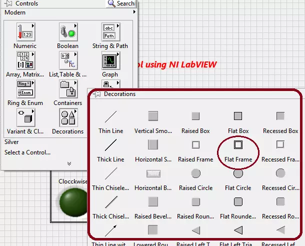
Go to Controls, Modern-> Decorations you can see different decoration blocks there.
All these blocks are shown in the figure displayed below.
I have used three decoration block encircled with the red color, to decorate my program.
Thick red boundary shows all of the decoration blocks to make your program attractive.
You can also decorate your programs using this amazing tool.
This is all from the tutorial DC Motor Direction Control in LabVIEW. I hope you all enjoyed this tutorial. If you face any sort of problem in DC Motor Direction Control in LabVIEW, then you can ask me anytime without feeling any kind of hesitation. I will try my level best to solve your issue in a better way if possible. I will explore NI LabVIEW further in my later tutorials. Till then, Take care :)
syedzainnasir
I am Syed Zain Nasir, the founder of The Engineering Projects (TEP). I am a
programmer since 2009 before that I just search things, make small projects and now I am sharing my
knowledge through this platform. I also work as a freelancer and did many projects related to
programming and electrical circuitry. My Google Profile+Follow
Get Connected
Comments on ‘’ DC Motor Direction Control in LabVIEW ‘’ ( 2 )
0
sahadevsingha
Says:
what is the connection that to be made between motor and arduino pins, please refer pin connection .
Reply
100
1
pawan
Says:
Please sir, share us pin connection between motor drivers and aurduino uno
Reply