

Few days ago, I have also posted a tutorial on XBee Arduino Interfacing, in which we have seen how to make wireless communication between two XBee Modules which is also an RF module. So, now we are gonna have a look at How to make Wireless Communication between two NRF24L01 modules. I hope you are gonna enjoy this nrf24l01 arduino Interfacing. Here's the video demonstration of NRF24L01 Arduino Interfacing:
Basics of NRF24L01
Before staring this interfacing of Arduino with 24L01, lets have a little introduction of nrf24l01 module. NRF24L01 is, in fact, a Radio Transceiver module and it operates on 2.4 GHz frequency. This module is a by default half- duplex fabricated module and it has the capability to send and receive data simultaneously. It's a very cheap & small sized module but it's features are astonishing. For example this module is capable of sending from 1 to 25 bytes of raw data simultaneously and the data transmission rate is up to 1 mega bytes per second. If we summarize all the features of this small size but big capability module then, we can say that:
- By using this NRF24L01 module we can send a message to a particular receiver.
- We can receive a message from some particular sender. (remember as I told earlier, we can do both the steps simultaneously).
- During sending the message through this module, we will have to specify the message sender's and receiver's address.
- Also we will have to specify the size of that particular message, which we are going to transmit through this module.
- In some particular applications, we also have to perform switching between the receiver and sending state. For example, if you are received a particular message then, we will stop the communication first and will read it and then you will send it. So in such situations, we have to perform the switching while sending or receiving data through this module.
- I encountered a problem of "Failed, response timed out" with NRF24L01+ while interfacing it with Arduino, if you got the same problem then read this post Interfacing of NRF24L01+ with Arduino - Response Timed Out. This nrf24l01 arduino example will help you in understanding this Response Timed Out problem.
NRF24L01 Arduino Interfacing
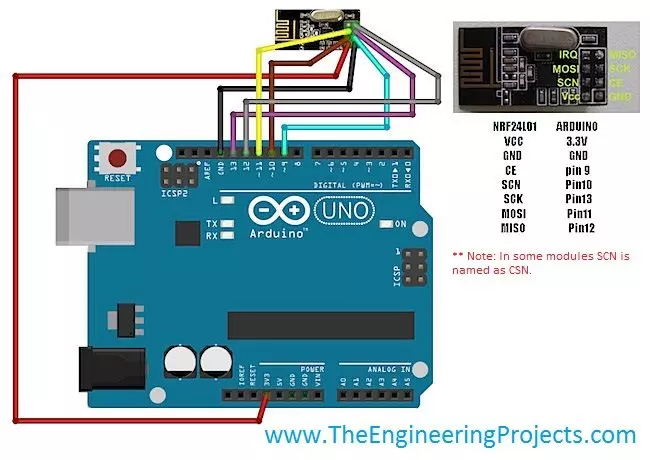
Arduino is a very powerful and versatile microcontroller board and it gives us the ease to perform multitasking. NRF24l01 has total 8 pins. The pin configuration and the function of each pin is described below:- The very first pin is for GND and through the pin#1 of this module, ground is provided to module.
- Pin#2 of this module is to provide power supply. This pin is designated as VCC. This module generally needs 1.9 to 3.6 volts for its operation. And in most cases we will apply 3 volts to it.
- Pin#3 is designated as CE and it is used to select the mode of operation. Either you are using this module to transmit data or to receive data.
- Pin#4 is designated as CSN and it is used to enable the SPI chip, embedded on the module.
- Pin#5 is used to provide SPI clock to the module. When this pin is HIGH then, clock is enabled and when this pin is LOW then, the clock to this module is disabled.
- Pin#6 is designated as MOSI and it is used to transmit data from this module to the external circuit.
- Pin#7 is designated as MISO and if we wish to receive data through this module from any external source then, this pin is enabled.
- Pin#8 is the last pin of this module and it is designated as IRQ pin.
NRF24L01 As Transmitter
- Connect your NRF24L01 with Arduino as shown in the below figure:
- Total 7 pins of NRF24L01 will be connected while the 8th pin IRQ doesn't need to connect.
- Now, next thing you need to do is to download this RF24 Library of Arduino and place it in the libraries folder of your Arduino software so that we could compile our code of nrf24l01 arduino example.
- We haven't designed this library, we are just sharing it for the engineers to use it in their projects.
- Now upload the below sketch into your Arduino which you want to act as Transmitter.
    #include <SPI.h>
    #include "nRF24L01.h"
    #include "RF24.h"

    RF24 radio(9,10);

    const uint64_t pipes[2] = { 0xF0F0F0F0E1LL, 0xF0F0F0F0D2LL };
    unsigned long Command = 1;
    void setup()
    {
    Serial.begin(57600);

    radio.begin();
    radio.setRetries(15,15);
    radio.openReadingPipe(1,pipes[1]);
    radio.startListening();
    radio.printDetails();
    radio.openWritingPipe(pipes[0]);
    radio.openReadingPipe(1,pipes[1]);
    radio.stopListening();
    }

    void loop(void)
    {
    radio.stopListening();

    radio.write( &Command, sizeof(unsigned long) );

    radio.startListening();

    delay(1000);
    }
- In this code, I have marked the variable Command, this is the variable which I am sending via NRF24L01, rite now its value is 1 which you can change.
- So, if you want to send 3 you can change its value to 3.
- Now lets design the receiver side.
NRF24L01 As Receiver
- Again connect your Arduino with NRF24L01 as shown in below figure. Its same as we did for Transmitter side.
- Now upload this below code into the Receiver and you will start receiving the value coming from transmitter.
    #include <SPI.h>
    #include "nRF24L01.h"
    #include "RF24.h"

    RF24 radio(9,10);

    const uint64_t pipes[2] = { 0xF0F0F0F0E1LL, 0xF0F0F0F0D2LL };

    typedef enum { role_ping_out = 1, role_pong_back } role_e;

    const char* role_friendly_name[] = { "invalid", "Ping out", "Pong back"};

    role_e role = role_pong_back;

    void setup(void)
    {
    Serial.begin(57600);
    radio.begin();
    radio.setRetries(15,15);
    radio.openReadingPipe(1,pipes[1]);
    radio.startListening();
    radio.printDetails();
    radio.openWritingPipe(pipes[1]);
    radio.openReadingPipe(1,pipes[0]);
    radio.startListening();
    }

    void loop(void)
    {

    if ( radio.available() )
    {
    unsigned long data = 0;
    radio.read( &data, sizeof(unsigned long) );
    Serial.println(data);

    delay(20);
    }
    }
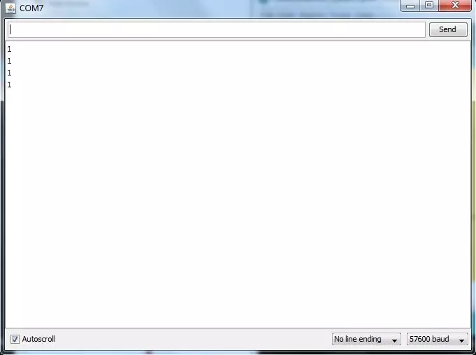
- Now open your Serial Monitor of Receiver side and you will see that you are getting "1" in the Arduino Serial Monitor, which is the value of Command variable we set in the Transmitter side, as shown in below figure:
- Its quite easy and I hope you will make it work in the first attempt but if you still got problem then ask in comments.
- I will share more Arduino Projects on this RF module soon.
