

Its maximum current gain is around 800. So, let's have a detailed overview of BC 547.
| Where To Buy? | ||||
|---|---|---|---|---|
| No. | Components | Distributor | Link To Buy | |
| 1 | BC547 | Amazon | Buy Now | |
Introduction to BC547
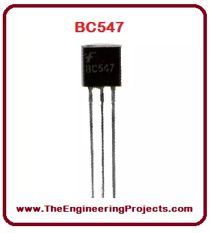
- BC547 is a 3-Terminal NPN Bipolar Junction Transistor(BJT), mostly used for switching purposes and current amplification.
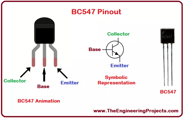
- BC547 Pins(Terminals) from left to right are called:
- Collector.
- Base.
- Emitter.
- Depending on the voltage applied at Base Terminal, BC547 can operate in two states, named:
- Forward Biased.
- Reverse Biased.
BC547 as Reverse Biased
- If Base Terminal is connected to the Ground(0V), Collector and Emitter will act as an open switch and the transistor is said to be acting as Reverse Biased.
- In a Reverse Biased State, no current will flow through the transistor.
BC547 as Forward Biased
- If a HIGH signal(normally 5V) is provided at the Base Terminal, Collector and Emitter will start acting as a closed switch and the transistor is said to be acting as Forward Biased.
- In Forward Biased State, the current will start flowing from Collector to Emitter.
- The maximum Collector current limit of BC547 is 110mA, so the load must be lower than that.
- Now let's have a look at the datasheet of BC547:
BC547 Datasheet
- If you want to get in-depth knowledge about any electronic component, then you should read its datasheet.
- You can download BC547 Datasheet by clicking the below button:
- Now, let's have a look at the pinout of BC547:
BC547 Pinout
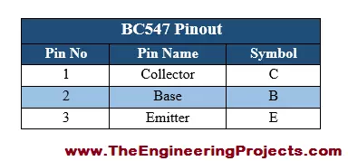
- BC547 Pinout consists of 3 pins in total, named: Collector(C), Base(B) and Emitter(E).
- All of these three pins along with their symbols are shown in the below table:
BC547 Pins Configuration
- The properly labeled pin configuration diagram of BC 547 along with its animation is shown in the figure given below.
- In the last section, we will design a Proteus Simulation of BC547, which will give you a better understanding of How to use these pins of BC547.
BC547 Transistor Working
- As we know BC547 is an NPN transistor, so in its design, a P-region(Base) is sandwiched between two N-type regions.
- At the border of the P and N, a depletion region is created, which blocks the flow of charge carriers from one region to another.
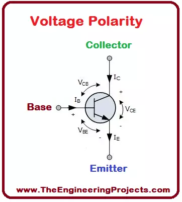
- When the input voltage is applied at its Base terminal, some amount of current starts to flow from the base to the emitter and controls the current at the collector.
- The voltage between the base and the emitter (VBE), is negative at the emitter and positive at the base terminal for its NPN construction.
- The polarity of voltages applied for each junction is shown in the figure below:
BC547 Ratings
- The current, power and voltage ratings of BC547 along with their values and System International (SI) units are provided in the table shown below.
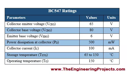
- Moreover, the storage temperature, as well as operating temperature for the transistor BC 547, is also given in the table shown above.
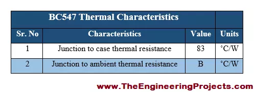
BC547 Thermal Characteristics
- The thermal characteristics associated with BC 547 are provided along with typical values, in the table shown below.
BC547 Applications
- There are a lot of applications associated with BC547, a few of the major applications are given below.
- BC547 can be used for switching purposes.
- We can also use it for amplification purposes.
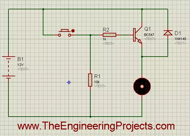
BC547 Proteus Simulation
- I have made a simple Proteus ISIS simulation using BC 547 for the control of the DC motor.
- The screenshot of the simulation is shown in the figure below.
- The running form of the simulation is shown in the figure below.
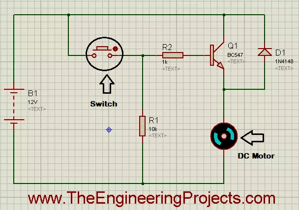
- By pressing the button encircled in the figure above, you will be able to observe the working of the DC motor.
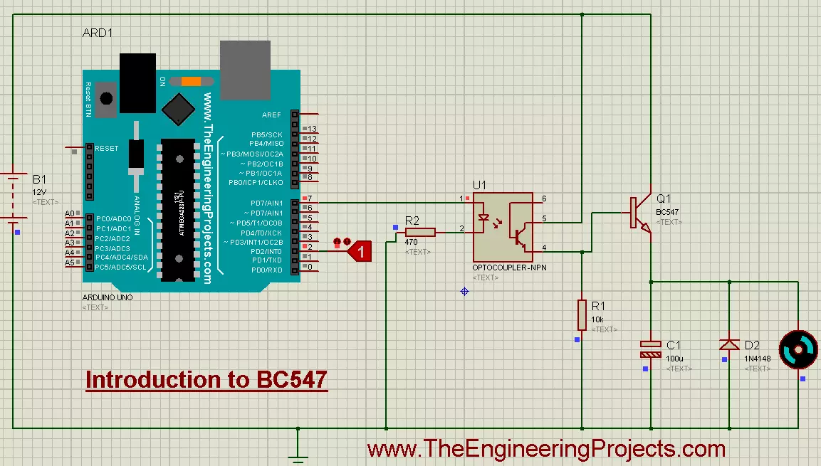
- I have made another simulation for DC motor control using Arduino UNO and BC 547.
- The simulation's screenshot is shown in the figure below.

- The source code for the above simulation is given below.
int MotorInput = 2;
int MotorOutput = 7;

void setup()
{
    pinMode(MotorInput, INPUT_PULLUP);
    pinMode(MotorOutput , OUTPUT);
}

void loop()
{
    if(digitalRead(MotorInput) == HIGH)
    {
      digitalWrite(MotorOutput, HIGH);
    }
    if(digitalRead(MotorInput) == LOW)
    {
      digitalWrite(MotorOutput, LOW);
    }

}
- The running form of the simulation is shown in the figure below.
- First of all, you need to change the logic state from 0 to 1, after uploading the hex file, the motor will automatically start to rotate.
