Hey Guys! Hope you are doing well. I always take pleasure to keep you updated with valuable information related to information and technology. Today, I'll discuss the detailed Introduction to ULN2803 which is a relay driver that comes with a high-voltage and high-current Darlington transistor array. In order to obtain higher current capability, the Darlington pairs are connected in a parallel configuration.
The component is incorporated with eight NPN Darlington pairs, featuring high-voltage outputs with common-cathode clamp diodes that are directly related to switching inductive loads. Each Darlington pair features a decent amount of collector-current rating i.e. around 500 mA.
You must have a look at ULN2003 which is almost similar to this IC but comes with 16 pins and can handle 7 relays at a time.
In this post, I'll cover each and everything related to this driver IC: its main features, pinout, working, and applications. Let's dive in.
Introduction to ULN2803
ULN2803 is a high-voltage and high-current Darlington transistor array and is mainly used as a relay driver with an ability to handle 8 relays at a time.
It comes with a collector-emitter voltage around 50 V and input voltage residing at 30 V.
Before we move further, we must know what is Darlington transistor? It is commonly known as Darlington pair which is nothing but a combination of two bipolar transistors featuring a compound design and is connected back to back where current amplified by the first transistor is again amplified by the second one.
This shape delivers a much higher current gain as compared to each transistor taken separately. It works on the simple amplification principle happening in the regular transistor where a small base is used to make the pair switch for higher switching currents.
This Darlington transistor mainly operates at 5V and is based on TTL (Transistor-Transistor Logic) and CMOS (Complementary Metal Oxide Semi-Conductor).
The NPN transistors forming arrays are useful for both: interfacing between low logic level digital circuitry and achieving the higher current/voltage requirements in a wide range of applications including printer hammers, lamps, relays, consumer and industrial applications.
The device shows open–collector outputs and freewheeling clamp diodes that turn out to be very handy for transient suppression.
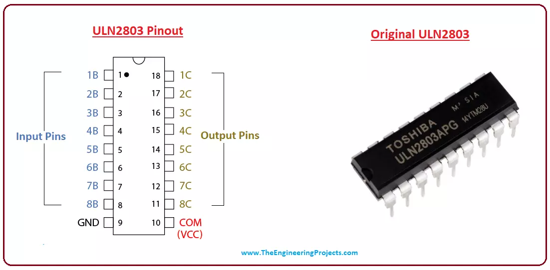
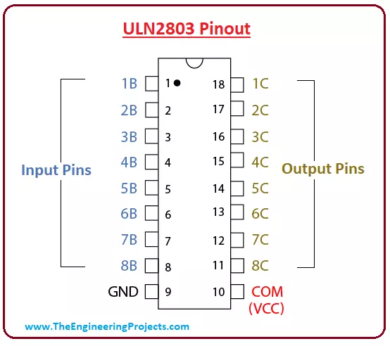
ULN2803 Pinout
Following figure shows the pinout of ULN2803. It comes with 8 input pins and 8 output pins.
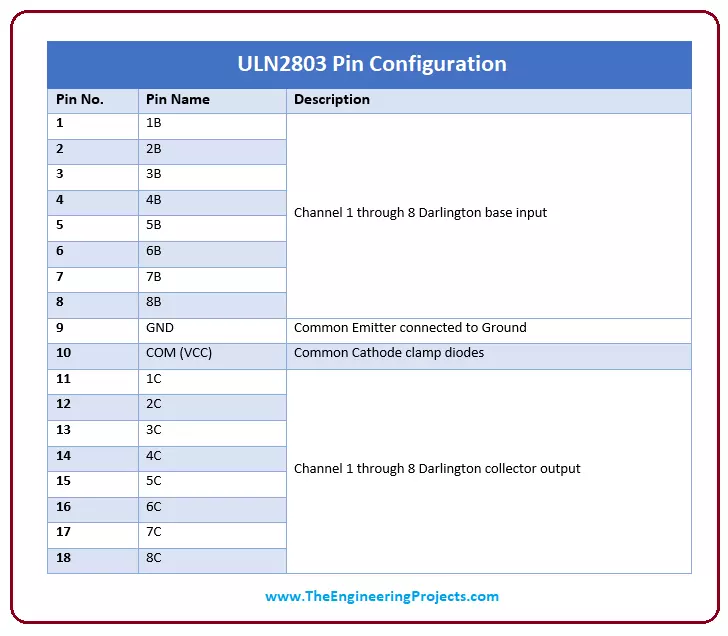
Pin Configuration
Pin number from 1 to 8 is a Channel 1 through 8 Darlington base input while pin number from 11 to 18 is Channel 1 through 8 Darlington base output. Similarly, 9 and 10 pins are ground and common cathode node (Vcc) respectively. It is important to note that common emitter is shared by all the channels.
Following table shows the pin configuration of ULN2803.
ULN2803 Logic Diagram
Following figure shows the logic diagram of ULN2803. It is a visual representation and arrangement of how the diodes are connected in the component.
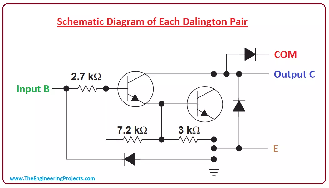
Following figure shows the schematic diagram of each Darlington pair.
You can see how the resistors and diodes are connected with each other. And the amplified output of one resistor is further amplified by the second resistor, giving a whopping amount of current gain which is difficult for the individual diode to achieve if incorporated separately.
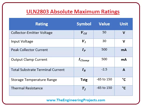
ULN2803 Absolute Maximum Ratings
Following figure shows the absolute maximum rating of this component.
These are the stress ratings which if exceed from absolute maximum ratings, can damage the device at large, ultimately affecting the overall nature and performance of the project.
Similarly, if these ratings are applied for the maximum period of time above normal operating conditions they can affect the reliability of the device.
Steps and measurements taken in the early stages of your project can save you from the atrocities of spending more in case the electronic circuit gets affected.
It is preferred to check these ratings before placing the device in the circuit and make sure these ratings are quite in line and match exactly as defined by the manufacturer.
Applications
ULN2803 comes with a variety of advantages with a common application as a relay driver. Following are some major applications of this Darlington array.
This is all for today. I hope you have found this read valuable. If you have any question, you can approach me in the comment section below. I'd love to help you the best way I can. Your feedback and suggestions are a valuable asset for us. Based on them, we develop our content strategy, so keep them coming. Thanks for reading the article.
syedzainnasir
I am Syed Zain Nasir, the founder of The Engineering Projects (TEP). I am a
programmer since 2009 before that I just search things, make small projects and now I am sharing my
knowledge through this platform. I also work as a freelancer and did many projects related to
programming and electrical circuitry. My Google Profile+Follow
Get Connected
Comments on ‘’ Introduction to ULN2803 ‘’ ( 2 )
0
Says:
This is almost all information that is available on a standard data sheet. There is not even a demo circuit showing a real life application. I saw this IC on another site being used as a voltage shifter from a 5v input to a 3.3v output. I came here looking for more information regarding similar applications and found a data sheet.
Reply
100
1
Says:
Nice tutorial!
I have searched for troubleshooting the ULN and came to this tutorial.
I use a ULN chip in a motor inverter for controlling precharge relay and main relay.
The problem is when the motor inverter is powered off, and for instance the charging is on (battery charging) the relay will kick in getting negative trough the unpowered ULN??? Sounds strange, but It's happening.
And I don't want the motor inverter ON all time (uses power and draining the battery)
Reply