

- Introduction to Pure Sine Wave Inverter.
- Components used in the circuit of Pure Sine Wave Inverter.
- Working of the circuit of sine wave inverter.
- Circuit simulation of pure sine wave inverter in Proteus.
Introduction to Pure Sine Wave Inverter
In electronics, we examine the output of devices in the form of waves. Basically, there are four types of waves including sine wave, sawtooth wave, square wave and triangular wave. The title of the circuit we are discussing today consist of two main concepts:
- Sine Wave
- Inverter
Let's recall them one after the other.
- Sine Wave: The sine wave is a mathematical curve that is a smooth, s-shaped, periodic, continuous wave and is described as the graph of sin function indicated by Y=sin x.
The sine waves are used in Mathematics, physics, engineering, signal processing and other related waves. In Electronics, the sine wave indicates the AC.
- Inverter: Inverters are the electronic devices that are used to convert the DC into AC. We can say, Inverters are the opposite circuits of rectifiers. The purpose of this inverter is the same.
Hence, when we combine these concepts, we get the following definition of Pure Sine Wave Inverter:
- "The Pure Sine Wave Inverter is a circuit that takes the input in the form of DC and gives output as AC. It is used to run any type of instruments designed to run on smooth sine wave output."
We can make the circuit with the many methods, out of which two are:
- Pure Sine Wave inverter through MOSFET.
- Pure Sine Wave Inverter through 555 Timers IC.
The focus of this article is the 2nd type. So let's look at its circuit.
Circuit of Pure Sine Wave Inverter using 555 Timer
If you understand the working of its components, the circuit of the sine wave inverter is quite simple. It consists of some simple electronic components that every engineer uses many times. But out of them, 555 Timer and Transformer should be discussed here.555 Timer
The 555 Timer is a great integrated circuit. It is used in thousands of circuits that have the requirement of pulses with uniform length. It is an 8 pin integrated circuit that may be used in three modes. In this tutorial, we'll use the 555 Timer in Astable Mode.Transformer
A transformer is a passive electronic device that is used to transfer electrical energy from one source to another by the mean of electromagnetic induction. The main purpose of the transformer is to change the level of the input current (high or low) to the output current. The circuit of Pure Sine Wave Inverter is designed so, we provide the 12V DC as input and get the 240V AC as output. In addition to these, we will use Inductor, diode, capacitor, resistor and power source in our circuit.Working of Pure Sine Wave Inverter using 555 Timers
- The working of the Pure Sine Wave Inverter starts when the 12 volts DC is applied to the components.
- These 12 volts enter the 555 Timer through pin 3 of the 555 timer that is in the Astable Mode. Due to this Mode, the 555 timer produces a single uniform pulse that is fed into the inductor.
- Every time, when a new pulse enters the inductor, it stores the energy in the form of an electromagnet. In the time t, when this energy is fully discharged through the inductor, its signs of induction change. After that, a new pulse enters the inductor and this process goes on. This energy passes through the resistor and finally fed into the transformer.
- In our case, the transformer is stepped high and it gives us the output of 240V AC. One can check this using AC Voltmeter.
- The diode connected to pin 7 of 555 Timer passes the current in only one direction (because it is a diode) and sends this pulse to the transformer by the mean of a capacitor for a steady pulse.
Simulation of Pure Sine Wave Inverter in Proteus
Using all the concepts discussed above, let's get started with the simulation of the circuit by following the simple steps.Required Devices
- 555 Timer
- Vsource (DC power source)
- Diode
- Capacitor
- Inductor
- Transformer
- Resistor
- Connecting Wires
- Ground Terminal
Circuit Simulation of Pure Sine Wave Inverter
- Excite your Proteus simulator.
- Start a new Project
- Tap to the "P" button of the screen and choose 1st seven devices one after the other from the list of required devices.
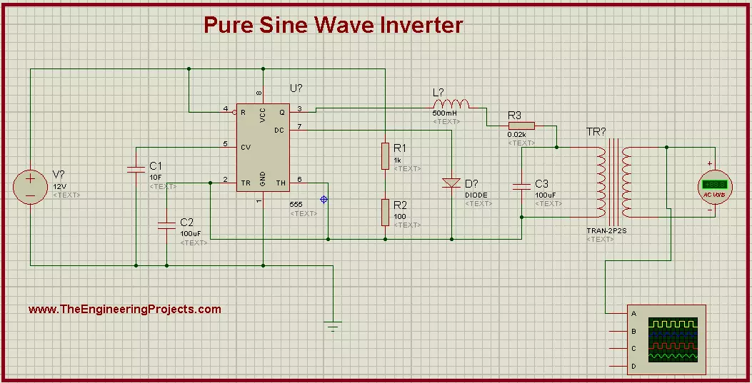
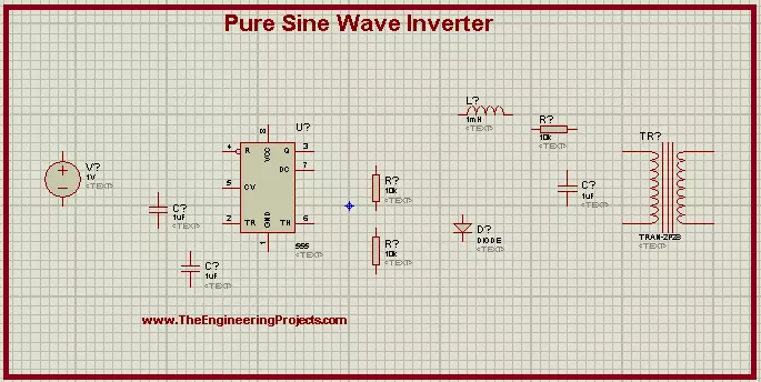
- Arrange all the devices on the screen by following the image given below:
- Left click on the screen>Go to Place> Terminal>Ground and set it just below the circuit.
- Change the Values of the devices according to the table given next:
Components Values R1 1KR R2 1KR R3 0.02KR C1 1nF C2 100nF C3 100uF Inductor 1mH Transformer Primary= 1H, Secondary= 2000H - Go to Instruments>Oscilloscope and set it at the output side.
- Connect terminal A with
- Now connect all the components carefully with the connecting wires.
- Click on the Play button just at the lower-left corner of the screen and start the simulation.
- You will find the Sine Wave Inversion on the output screen of the Oscilloscope.
