

The traffic light is one of the most important applications we see everyday everywhere we go back and forth. Controlling traffic signs was managed by people which was very problematic and headache on travelers and the officers as well. But nowadays, most traffic lights are controlled by automatic control systems. The brain that handles the complicated logic behind the traffic light control system is a PLC and one programmer like you guys has written its logic. So today we have come back to enjoy programming such a critical and large project by using ladder logic programming and for sure will apply the code and the logic we write into the simulator to check its correctness.
Problem we try to solve
First of all, the scene we captured below by figure 1 shows two ways to cross a traffic signal, the biggest and most complicated traffic sign you might see anywhere you go. We need to go through the logic and requirements and then list these alongside with the restrictions for realizing the safety which is very critical and crucial right here for saving people and vehicles traveling in each way in the cross traffic light. The complete project will be divided into two tasks to simplify the project and each task will be an exercise for you guys to do. So without any further delay let’s jump into our project’s exercises.

Project description
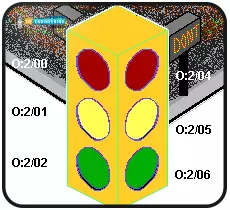
As you can see in figure 2, there are two faces of three traffic lights, one for each side way to control the cross traffic light. Each traffic light side has three indicators RED, green, and Ampere to represent the stop, ready-to-cross, and about-to-change that tells the car drivers and pedestrians when to stop and what time they can continue crossing. Each lamp has assigned to one output as you can see guys in the image. Our task is to control the timing of lighting each indicator to achieve the whole process. As we have mentioned earlier we are going to work the project into couple of milestones. So let we names two milestones in the first one we are going to control one way and will complement the work by adding the code to manage the two crossways by reaching that point we will have completed our mission. So let’s getting into the work.
The one way control Part 1
Table 1 below lists the required amount of time and the sequence of the lighting of each indicator for controlling one way of the cross traffic light control project. As listed in the table below, the red light is connected to output O:2/00 and it is required to light it for 12 seconds. Then the green light that is connected to output O:2/02 should be lit for 8 seconds and finally the Amber light for 4 seconds which is connected to output O:2/01. Remember my friends, we need to repeat the process forever.
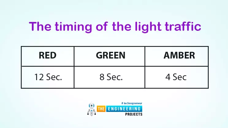
RED |
GREEN |
AMBER |
12 Sec. |
8 Sec. |
4 Sec |
The ladder logic code
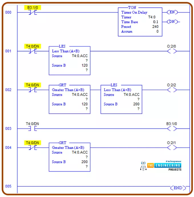
Figure 3 shows the program of the first part to control one way. You notice guys the program is mainly based on utilizing timers. The idea is simply to start with an on-delay timer of the whole period which is 24 seconds. As it is clear the first rung energizes the timer T4: 0 to start timing for 24 seconds. Then by comparing the accumulating time, the second rung activate the green light for 8 seconds by using the comparing instruction LES in the way like keep energize the red light that connected to O:2/0 as long as the the accumulator of T4:0 which is is T4:0.acc less than 12 seconds. In the same way, in the period between 12 to 20 seconds the green light is activated for 8 seconds thanks to using the comparing instructions GRT and LES. And finally command the amper light to energize after 4 sec to the end. Notice my friend to let the process repeat forever, the timer is cleared or restarted by enabling the flag B3:1/0. Let us test the logic we have just implemented to see if it can work fulfilling the requirements or not.
Testing part 1 using simulator
The evaluation of the first part is depicted by figure 4. See guys the red sign is lit for 12 seconds and the green light follows for 8 seconds as shown in figure 5.
And figure 6 below depicts the ampere lighting for 4 seconds. Now you can see we have completed the first part.
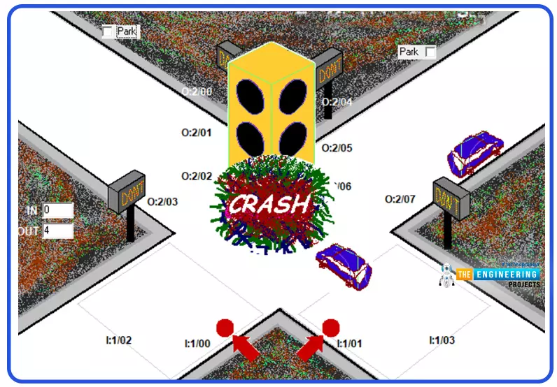
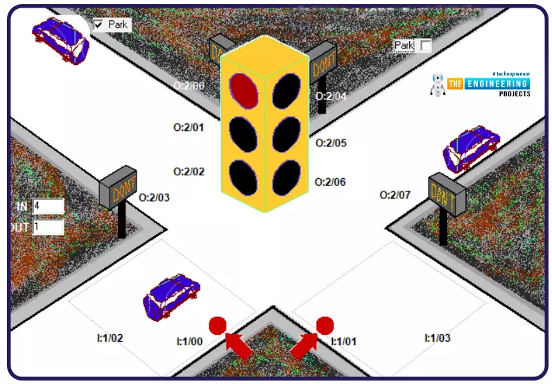
But wait my friends as we can not proceed with the project and let it be working at this stage do you know why? Exactly, it is not safe because the control has not been programmed for the other way so the results would be sad as shown in figure 7.
The project second part
As we mentioned earlier, the project has been achieved by dividing it into two parts. In the first part that we have just demonstrated above including the ladder logic program and testing using our simulator. That very part, part one can control one way traffic but we have two running traffic lights that should be considered. From here we are going to show the second part of the project. Let us start with the requirements.
Part two the requirements
Table 2 below asks you guys to control both traffic ways to have the red light on one side for a 12 seconds period time in which you need to allow the green light of the other way to light for 8 seconds and then the Amber light will be permitted for the next 4 seconds. The same logic will be applied on the reverse side. On another word, side number one is red with green and amper of side number two. Also, red of side number two with green and amper of side number one. Let us see the ladder logic and description of the implemented logic in the following section.
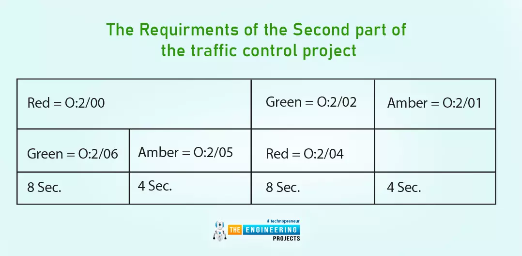
Red = O:2/00 |
Green = O:2/02 |
Amber = O:2/01 |
|
Green = O:2/06 |
Amber = O:2/05 |
Red = O:2/04 |
|
8 Sec. |
4 Sec. |
8 Sec. |
4 Sec. |
Logic of the second part
For the length of the program” We have divided it into two pieces. The first one is shown in the figure 8. You can see guys, it is similar to utilize the timers and compare instructions to accomplish the project. Like part one but adding amendments to combine the second part requirements. in the third rung you notice my friends we have added just restriction to not letting the green and amber light of one side while the green or amber does in the other side and vise versa. So what we are doing in the first four rungs is to handle one way traffic signal with restricting the other side when it is needed. Now let us move to the second part of code.
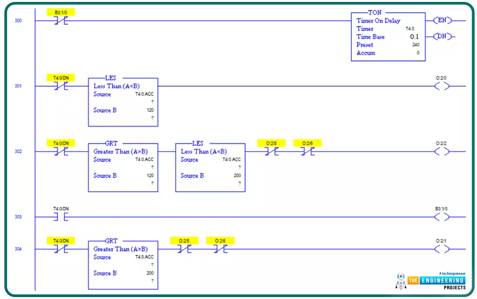
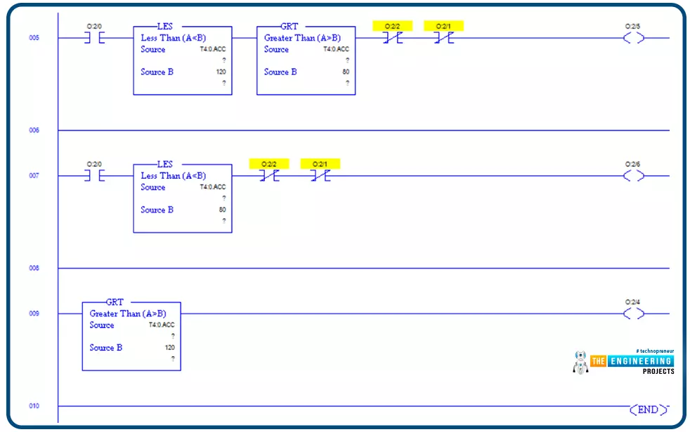
Figure 9 demonstrates the control of the other side by adding the logic for the green of the other side as in rung 5 considering the restriction of the green and amber of the side one at that time. Then in rung 7, the control for the amber light of side 2 considers inhibiting the amber and green of the side one for avoiding the crash to happen. And at last the red light is energized for 12 seconds in which the green and amber of the other side are not prohibited. Now time to test our logic has come so let us go testing that program.
Testing the completed project
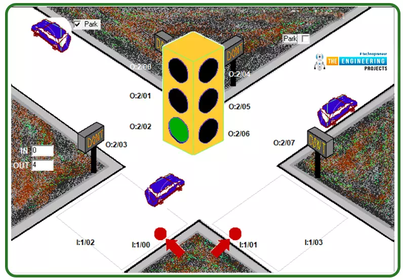
Here you can see friends the test of the completed project in figure 10. Notice that one side has the green light on and the other side shows the red is lighted. As a result, the side with green light on allows the vehicles to pass while the side with red sign lighted in bit cars from passing.
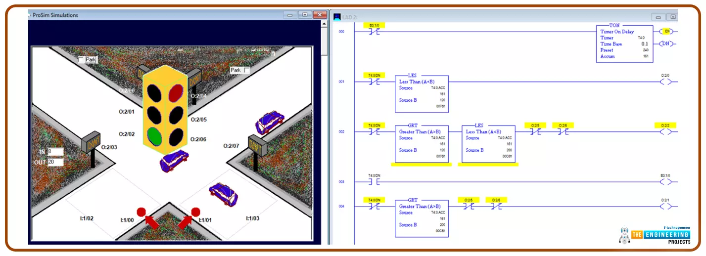
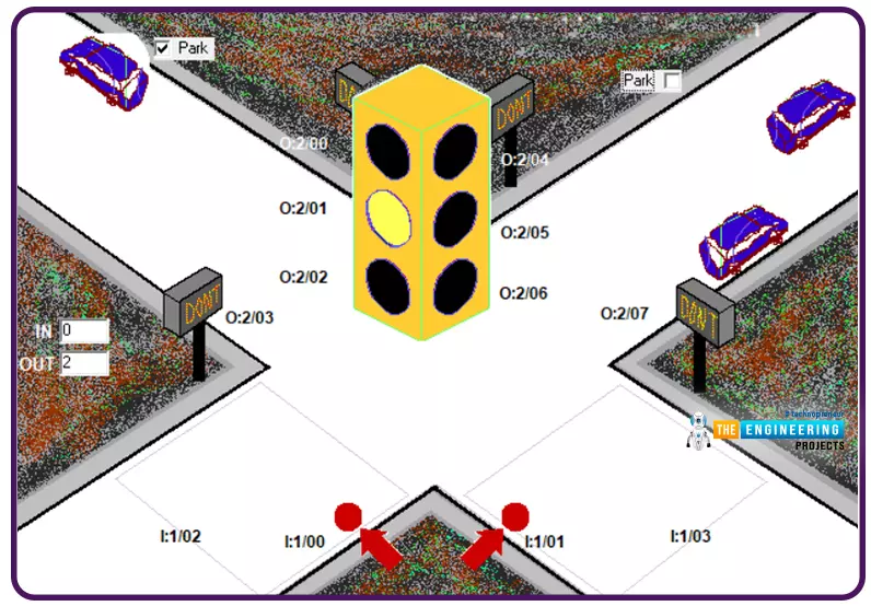
More testing to check the opposite scenario for checking the cross traffic logic. Figure 11 shows the other side amber sign is on while the red of the opposite side is on. Therefore, the cars are allowed with the side that has the amber light on. On the other hand, the side that has the red light is one prevent cars from passing.

My friends, I really appreciate you following up to that very point and hoping you have got to learn and enjoy practicing one of the most important projects that you might see in everywhere you go in your daily life. Please know one thing which is very important that, the code we have implemented just right here is not the only way to solve such project. There are dozens of way to code such a project so please try your way without hesitation and keep trying to increase your knowledge and boost professionally in ladder logic programming. Thanks again guys and let us meet in another tutorial and project of the real life problem to learn and enjoy practicing ladder logic programming together.
