

Arduino Pico is the world’s smallest Arduino compatible board, as said by Arduino Official Page. Because of its small size & low weight, it is normally used in autonomous projects i.e. drones, robots, quadcopters etc. where size is the real issue.
Arduino boards are introduced in modern electronics, to make projects economical and easy to design. A common man with no prior knowledge about programming can get hands-on experience with them. This smallest Pico version is readily available to turn your innovative thoughts into reality.
I suggest you read this post all the way through as I’ll detail the complete Introduction to Arduino Pico covering datasheet, pinout, features, pin description, programming and communication and applications.
Let’s get started.
Introduction to Arduino Pico
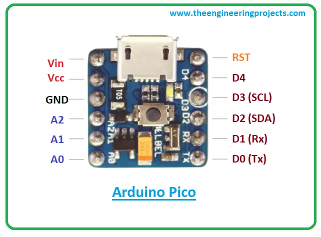
- Arduino Pico is a small-sized(0.6" x 0.6"), breadboard-friendly and Arduino-Compatible Microcontroller board, based on Atmega32u4 Microcontroller, contains 15 pins onboard and developed by MellBell Electronics(a Canadian company confounded by MOHAMMAD MALHAS & AHMAD NABEL).
- Leonardo compatible bootloader is pre-installed in Arduino Pico.
- The small size of 0.6” x 0.6” and 1.1g weight is what makes it special for a range of autonomous applications i.e. quadcopters, robots, automation etc.
- Arduino Pico comes with 8 digital input/output pins.
- It also contains 3 analog I/O pins used for interfacing analog sensors.
- Out of 8 digital pins, 1 Pin can also be used for generating PWM pulses and its Pin # D3.
- Arduino Pico board operates at 5V while the input voltage ranges from 7V to 12V.
- The maximum current rating of Arduino Pico is 40mA, so we can't attach a load drawing more current than that.
- The board also contains one micro USB Type-B Port, a reset button and a Reset pin.
- Arduino Pico supports two types of Communication Protocols: (We will discuss them later in detail)
- Serial Protocol.
- SPI Protocol.
- The flash memory is 32KB out of which 4KB is used by Bootloader. It is the memory where the sketch is stored. (The code we compile on Arduino IDE software is called a sketch)
- It comes with an SRAM memory of 2.5KB, it's even greater than that of UNO(where SRAM is 2KB).
- It has a crystal oscillator of 16MHz, so it's as fast as UNO or Nano.
- On its Kickstarter page, it's available in multiple colors(around 20 different colors).
- Mellbell also offers an aluminum version of the board that can be used in overheated environments and applications.
Arduino Pico Datasheet
Before you apply this board to your embedded project, it’s wise to scan through the datasheet of the device that features the main characteristics of the board. You can download the datasheet of Arduino Pico by clicking the link below:
Arduino Pico Features
The following are the main features of the Arduino Pico board.- Based on the ATmega32u4 microcontroller,
- Runs at a clocked frequency of 16 MHz
- 40 mA DC current per I/O pin
- 2.5KB of SRAM memory
- Bootloader: Leonardo compatible
- Reset: 1 pin
- 3 SPI pads on the back of the board
- 32 kB of internal Flash (4 kB used by the bootloader)
- 8x digital I/O pins, 1x PWM channel, and 3x analog input channels.
- The operating voltage is 5V.
- Input voltage range = 7 to 12 V.
- 6 x 0.6 inches size. Weight of 1.1 grams
- Bootloader compatible with the Arduino Leonardo
Arduino Pico Pin Description
- Hope you’ve got a sneak peek of this smallest Arduino board. In this section, we’ll detail the pin description of the pins installed on the board.
Analog Pins
- There are 3 analog pins available on the board. These pins can get any number of values in opposed to digital pins which get only two values i.e. HIGH and LOW.
PWM Pins
- This board incorporates one PWM channel which is employed to receive some of the analog output’s functions. When the PWM is activated, the board generates analog results with digital means.
Digital Pins
- Total 8 digital pins are employed on the board. These pins are introduced to be configured as inputs or outputs according to the requirement. These pins remain ON or OFF. When they are in the OFF state they are in a LOW voltage state receiving 0V and they are in HIGH voltage state they receive 5V.
Atmega32u4 Pinout
- The following figure represents the pinout diagram of Atmega32u4.
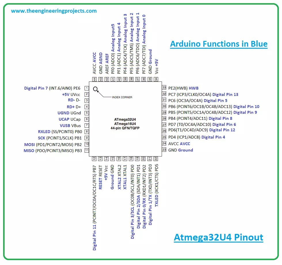
Atmega32u4 Pin Description
- In this section, we’ll detail the pin description of each pin available on Atmega32u4.
Vcc
- Digital voltage supply pin.
GND
- Ground Pin.
Port B (PB7...PB0)
- Port B is attached with pull-up resistors and is an 8-bit bidirectional I/O port. The pull up resistors are mainly employed to limit the current. This port is more efficient and contains better driving capabilities compared to other ports.
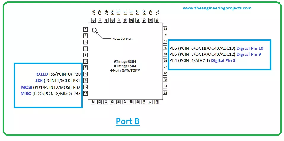
- When the pull up resistors are activated in this port C, it will source current with port pins extremely pulled low.
Port C (PC6, PC7)
- Port C is an 8-bit bidirectional I/O port that contains pull-up resistors.
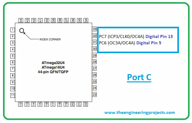
- When the pull up resistors are activated, Port C is used to source current with port pins extremely pulled low - Similar to Port B.
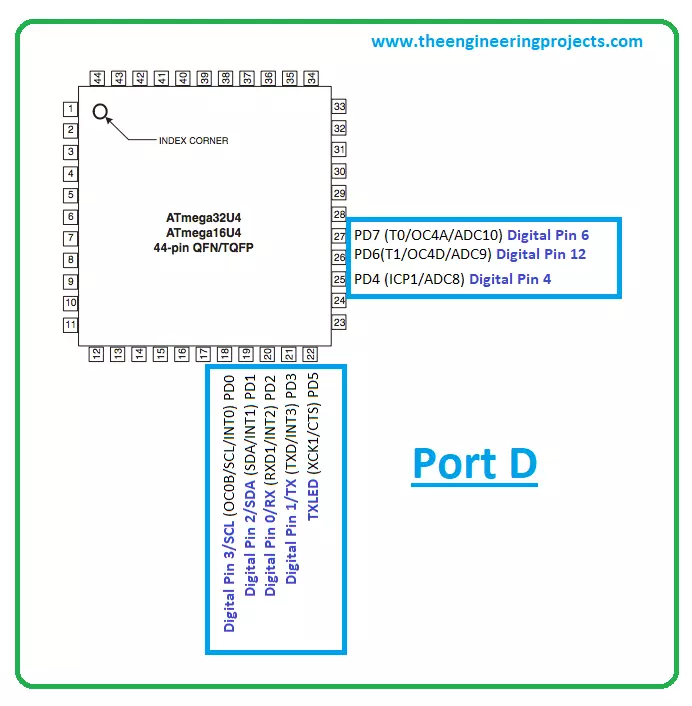
Port D (PD7..PD0)
- Port D is a bi-directional 8-bit I/O port with pull-up resistors. When the reset condition is activated, the Port D pins are tri-stated.
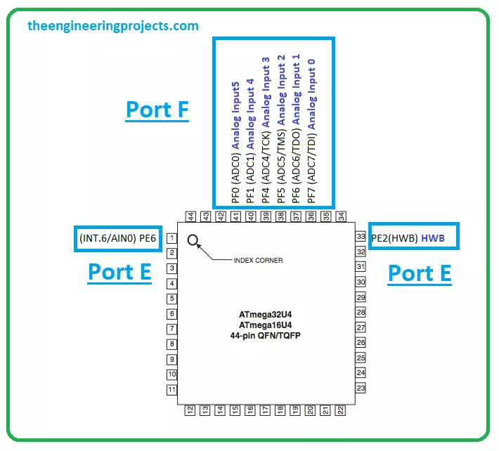
Port E (PE6, PE2)
- Only two bits PE6 and PE2 are available on the product pinout. It is an 8-bit bidirectional port that features internal pull up resistors to limit the current.
Port F (PF7..PF4, PF1,PF0)
- Port F is a bidirectional port that serves as analog inputs for the A/D converter. Two bits PF2 and PF3 are not available on the device pinout.
D+
- USB Full speed / Low Speed Positive Data Upstream Port. It is connected to the USB D+ connector pin employed with the serial resistor 22W.
D-
- USB Full speed / Low Speed Negative Data Upstream Port. It must be connected to the USB D- connector pin incorporated with serial resistor 22W.
UGND
- This is USB pads ground.
UCAP
- USB Pads Internal Regulator Output supply voltage.
UVCC
- USB Pads internal regulator Input supply voltage.
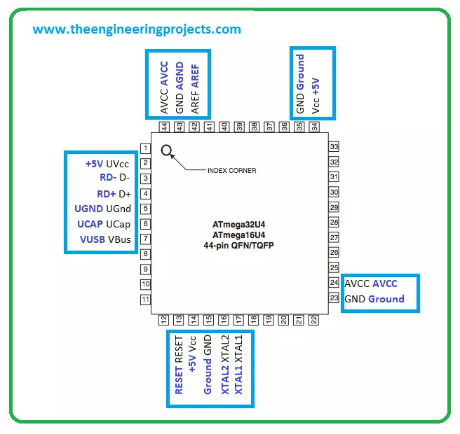
VBUS
It is USB VBUS monitor input.XTAL1
- Input to the inverting Oscillator amplifier and Input to the internal clock operating circuit.
XTAL2
- Output from the inverting Oscillator amplifier.
RESET
- A reset pin. When a low level applied to this pin for a longer period of time, it produces a reset. It is important to note that shorter pulses may not generate a reset.
AVCC
- AVCC is the supply voltage pin for all the A/D Converter channels.
AREF
- This pin is utilized as the analog reference pin for the A/D Converter.
Communication and Programming
- The module comes with different communication protocols including I2C, and UART.
- The UART is a serial communication protocol that carries two lines Tx and Rx where the former is a transmission line used to transfer the serial data and the latter is a receive data line used to receive the serial data.
- The I2C is a two-wire communication protocol that contains two lines named SCL and SDA. The SCL is a serial clock line that is used for the synchronization of all data transfer over the I2C bus while SDA is a serial data line mainly used to carry the data.
- Arduino IDE is the professional software developed by Arduino.cc that is used to program all types of Arduino Boards.
- Connect the board through USB to the computer and test and program the board as you like better.
Arduino Pico Applications
- Creating a wireless keyboard
- Water level meter.
- Health and security systems
- Student projects
- Embedded systems
- Industrial automation
- Automatic pill dispenser
