If you want to decorate your landscape and table for any formal events or holidays, table runners should be the first thing to cross your mind. Table runners are known as the base of your decorations. This is why most house owners prefer table runners instead of other decorating methods. Even though the primary objective of table runners is to protect the table from damages, its effectiveness is much more than that. Table runners will allow you to add style and color to your dining table. It will also help you to increase the overall design and mood of the event.
Table runners are available in various fabric materials such as linen, polyester, cotton, and satin that might make the purchasing process of the table linens a daunting task. No matter i ...
In our previous article, we grasp knowledge about real-life examples of the Internet of things. Now in this article, we try to elaborate on real-life applications of the Internet of things. Now a question may arise in your mind what’s the difference between the application of the Internet of things and examples of the Internet of things. I would be happy if you may elaborate on your question in addition. Simply associate degree example shows how applications are also created. Like there are several functionalities on the market in terms of arthropod genus and strategies however with examples it might be additional clear. Even so these functionalities are also wont to produce one thing awe-inspiring. In short, examples of the Internet of things is a task that is performed to develop a skil ...
Hello friends, How are you doing? Today, we have a very interesting topic of PLC ladder programming which is how to detect the transition between true and false and from low to high?. I know you are asking why do we need that? Well! Imagine my friends, we want to start a motor when the input signal state changes from high to low or from false to true. Let us give two examples to highlight the edge detection techniques. Good examples of using edge detection-based logic are timers and counters. In counters, they are energized to count up or down when a signal appears and the same for timers. Figure 1 shows the difference between using the edge to control a motor. In the top part, the motor is controlled by an input switch. the output is ON and OFF b ...
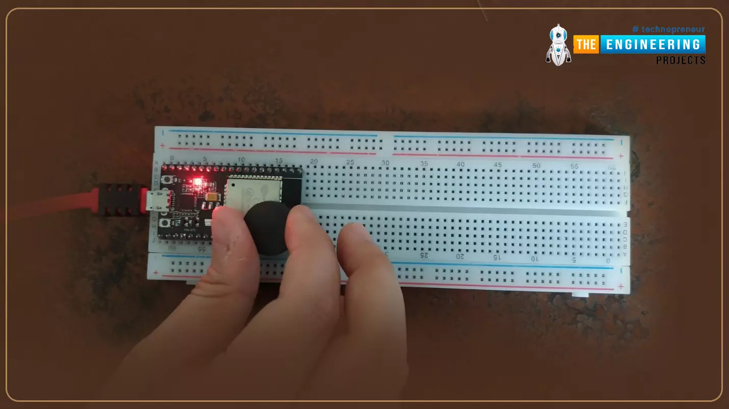
Hello readers, I hope you are all doing great. Welcome to the 2nd lecture of Section 5(ESP32 Sensors) in the ESP32 Programming Series. In the previous tutorial, we discussed the built-in ESP32 Hall Effect Sensor. In this tutorial, we will discuss another inbuilt sensor of the ESP32 i.e. Capacitive Touch Sensor.
ESP32 Board has 10 built-in capacitive touch pins, which generate an electrical signal when someone touches these pins. These ESP32 touch pins are normally used to wake up the board from deep sleep mode. These touch pins are also used to replace the normal mechanical buttons with touch pads, improving the presentation of the IoT projects.
Here's the video demonstration of the ESP32 Capacitive Touch Sensor:
Before going forward, let's first understand how this touch sens ...
There's a flock of noise at the instant concerning the Internet of Things(IoT) and its impact on everything from the method we travel and do our looking to the method makers keep track of inventory. However, what's the web of Things? how will it work? And is it genuinely that important?
Introduction to Internet of things
What is the Internet of Things?
In short, this technology connects any device to the net and plenty of different devices. In easy terms, this can be a classy network of things connected with one another. This network collects and shares information and data.
The devices embody a variety of objects, like good microwaves, self-driving cars, wearable devices, and complicated sensors, to ...
Hello geeks, I hope you all are doing well and looking forward to making something new yet interesting. So, today we have come up with our new project which is a calculator using Arduino.
We all use calculators in our daily life, whether you are working in an office or counting money at the bank, you are buying your daily grocery or doing shopping online, you will find calculators in different forms everywhere. In fact, the computer was initially considered a giant calculator. So if it is that common, why do we not make our own calculator?
Before going into the details of the project, it is good to know some history of that, let’s know some facts about the calculator. So the first known device for calculation is Abacus. And the first digital calcu ...
Hello guys! I hope you’re all in a good mood today because we are going to review the design of an interesting project today. We’ll be looking to design 4-way traffic lights in such a way that their delay is variable and is dependent upon the traffic density. This project is of intermediate difficulty level for people studying in undergrad engineering school with electronics, electrical and mechatronics as their major. It is also for the people learning Arduino and basic circuit design on their own or through some course. We have already designed a Simple 4-Way Traffic Light Control using Arduino and today we will make it smart by adding a variable delay.
Variable 4 Way Traffic Light:
As you all already know the importance of traffic lights and t ...
Hello everyone, welcome to today article which we are going to have a look at how technology has evolved the online casino industry. Some of you might be having knowhow on what casino industry is and some might be having partial or no knowledge at all. So, we are going to start with simple things as we advance our topic of discussion further. You should also have a look at the Technology behind Online Casinos.
Definition of the global casino industry
The global casino industry is an industry that is made of facilities that involves predictions of outcomes of the final result that will be obtained after an invent has passed. The predictions are made before the event has started. It is made up of the gambling activities such as the gaming machines ...
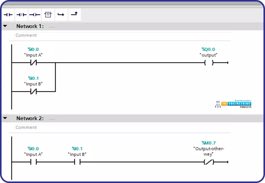
Hello friends! I hope you are all very well! I am so happy to meet you today to continue learning and practicing PLC ladder logic programming. In an earlier part, we already have gone through the very basic logic gates of “AND”. “OR”, and “NOT”. Today we are going to resume the simulation of logic gates. We have started and gone through simulating the basic logic gates which are “AND”, “OR”, and “NOT” as they are the most important basic logic gates by which we can form other logic gates. However, because the logic of large-scale projects is getting more and more complicating, a lot of time we have to use the other functions to do tasks faster. For example, we have shown in the logic gates article that, XOR can be used to compare two inputs and ch ...
Hello readers, I hope you all are doing great. Welcome to Section 5 of the ESP32 Programming Series. In this section, we are going to interface different Embedded Sensors with the ESP32 Microcontroller Board. ESP32 development board is featured with some inbuilt sensors(i.e. hall effect sensor, capacitive touch sensor) so, in the initial tutorials of this section, we will explore these built-in ESP32 sensors and in the later lectures, we will interface third-party sensors with the ESP32.
In today's lecture, we will discuss the working/operation of the ESP32 built-in Hall Effect Sensor. Hall Effect sensor is used to detect the variation in the magnetic field of its surroundings. So, let's first understand What's Hall Effect:
What is the Hall Effect?
The Hall Effect phenomenon was fir ...