Introduction to Arduino Esplora

Hi Guys! Hope you’re well today. I welcome you on board. In this post today, I’ll walk you through the Introduction to Arduino Esplora. Looking like a videogame controller, the Arduino Esplora is an electrical device that contains an Arduino Leonardo board (microcontroller) and a number of outputs and inputs. There are a colored LED and a buzzer as outputs. And there is a light sensor, four buttons, a joystick, a microphone, an accelerometer, and a temperature sensor as inputs. In other words, it is just like another Arduino Board with integrated actuators and sensors. Just stay with me for a little while, as I’m going to document the complete Introduction to Arduino Esplora covering pinout, working, pin description, how it’s different than other Arduino boards, and applications. Let’s jump right in.

Introduction to Arduino Esplora

  • Introduced by Arduino.cc, the Arduino Esplora is an electrical device that is based on the Arduino Leonardo board and contains integrated actuators and sensors.
  • Similar to the Arduino Leonardo, the Esplora board is incorporated with an Atmega32U4 AVR microcontroller that carries a 16 MHz crystal oscillator.
  • The Esplora comes with onboard light and sound outputs, and many input sensors, like a temperature sensor, an accelerometer, a joystick, a slider, a light sensor, and a microphone.
  • It also contains two Tinkerkit input and output connectors to enhance its capabilities and a socket used for the LCD screen.
  • Arduino Boards like Arduino Esplora are developed to provide both hardware and software platforms in one place. You can control the board with Arduino software as you like better. Plug and play with the device without getting hands-on experience in electronics.
  • It can mimic a keyboard or mouse that gives you the ability to use it with any 3D software.
  • Arduino Esplora board contains two actuators and 11 inputs. It carries a light sensor, an accelerometer, a multiplexer, and a mic, an RGB LED, and a buzzer.
  • This board contains all built-in sensors and actuators, the reason it’s easy to program and easy to handle through Arduino IDE software.
  • The Arduino Esplora is a great package for beginners, with built-in features, giving you the ability to plug and play with the device and get desired results on the fly.
  • This board is not compatible with the Arduino Shields, but you can connect this device with the external LCD module.
  • To connect the other modules, this device carries two output and two input ports. These ports are compatible with the signal, voltage, and ground pins and are known as 2 pin TinkerKit ports.
  • The Arduino Esplora is an ideal pick for creating a remote control device for your electrical project. You can develop external communication with your project without any hassle.
  • A micro USB cable is attached to the board, and it carries almost everything to get you started without having to combine and assemble anything from outside.
  • Information is extracted from the inputs and is used to write the program in the software which is then used to control the outputs on the board or your computer just like a remote controller.
  • Arduino Esplora is compatible with the Arduino IDE (Integrated Development Environment) like other boards.
  • Plus, you can also run this device with Arduino Web Editor that is hosted online and is incorporated with the latest support and features for all boards. Read this guide on how to use this browser and upload your sketches online.
  • And if you want to use this board offline, you need to install the Arduino IDE desktop version.
  • This board contains everything built-in to get you started. You need to simply connect the board with the computer through USB cable and start your work.
  • The reset pushbutton is located at the upper left corner that is used to restart the board.
Esplora carries four LEDs as follows:
  • ON LED is colored green that identifies if the board is getting a power supply
  • Accessible through pin 13, L is a yellow LED that is directly connected to the microcontroller.
  • RX and TX are yellow LEDs that determines the information received or transmitted through USB communication.

Arduino Esplora Features

The following are the sensors available on the Esplora board:
  • Joystick
  • push-button of the joystick
  • microphone
  • light sensor
  • 2 TinkerKit input connectors
  • temperature sensor
  • 4 separate push-buttons
  • Accelerometer
The following are the actuators present on the board:
  • RGB LED
  • Buzzer
  • 2 TinkerKit connectors

Arduino Esplora Set up with Windows

  • First, you require a standard software developed by Arduino.cc known as Arduino IDE. This software is used to program and control the board through your system.
  • Now connect the board with the computer through micro USB that is used to transfer the program from the computer system to the board.
  • As you connect the cable the green power LED (labeled ON) will turn on and then the yellow LED will start glowing that is marked ‘L’. The yellow LED will go blinking on and off after 8 seconds indicating your board is connected with the computer.
  • When you connect the board, the Windows will automatically start its driver installation process. It the installation process doesn’t start automatically, go to the windows device manager then (Start > Control Panel > Hardware) and go to the Arduino Esplora listing. Right-click this listing and pick Update driver.
  •  At the next popped up window, select "Browse my computer for driver software", and click Next
  • Now click the ‘Browse’ option. It will return another window: find the folder with the Arduino software that you have installed. Choose the drivers folder and click OK, then click the ‘Next’ button
  • You will get a notification that reads, “the board has not passed Windows Logo testing.” Click on the option “Continue Anyway.”
  • After a while, a window will open that reads “Windows has finished installing the driver software for this device” Now click the ‘close’ button.
These instructions are for the system having Windows 7 operating system. If you have a MAC or Linux then read this post on how to connect Arduino Esplora with the system. All pictures placed here are from Arduino.cc

Applications

The following are the applications of Arduino Esplora.
  • Used in Arduino Wifi remote controller
  • Used in robotics and electronics
  • Incorporated to identify free-fall detection using an accelerometer
  • Employed to emulate mouse or keyboard
That’s all for today. I hope you find this read helpful. If you have any questions, you can approach me in the section below, I’d love to help you the best way I can. Feel free to keep us updated with your valuable feedback and suggestions, they help us generate quality work customized to your exact needs and requirements. Thank you for reading the article.

Introduction to TIP42

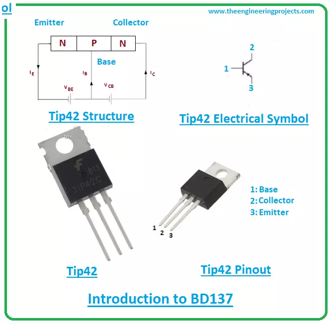
Hi Guys! Thank you for clicking this read. Hope this finds you well. In this post today, I’ll document the Introduction to Tip42. Tip42 is a medium power silicon transistor mainly used for switching and amplification purpose. It belongs to the PNP transistor family and comes in the TO-220 package. The collector current is 6A which signals it can support load under 6A. Both collector-base and the collector-emitter voltages are 40V. And the only 5V is required to initiate the transistor action as the emitter-base voltage is 5V. The power dissipation is 65W which defines the amount of energy released during the working of this transistor. The storage junction temperature is -65 to 150C and transition frequency is 3MHz. Just stay with me for 2-min as I’ll be discussing the main features, pinout, datasheet, and applications of the device Tip42. Let’s jump right in.

Introduction to TIP42

    • Tip42 is an epitaxial medium power silicon transistor mainly used for switching and amplification purpose. It falls under the category of PNP transistor and comes with current gain ranging from 15 to 75.
    • This current gain demonstrates the capacity of transistor it can amplify the current. It’s a ratio between the output current and input current.
    • Tip42 is a bipolar transistor which means two charge carriers are used in the conductivity process inside the transistor.
    • Both electrons and holes take part in the conductivity process. And in this case of PNP transistor, holes are majority carriers. And electrons are minority carriers in the case of NPN transistors.
  • This PNP transistor contains three terminals called the emitter, base, and collector. All these terminals carry different functionality and different doping concentration.
  • This different doping concentration is the main reason this bipolar transistor is not symmetrical. The external circuit is connected with the transistor through these terminals.
  • Tip42 is composed of two p-doped layers and one n-doped layer. The n-doped layer is sandwiched between the two p-doped layers. The two p-layers represent the collector and emitter terminals and the n-layer represents the base terminal. The N sign shows, a negative voltage is applied on the base terminal to trigger and start the transistor action.
  • This bipolar transistor controls the small input current and produces the large output current, the reason these devices are called current-controlled devices because two charge carriers are used for conductivity in contrast to FETs(field effect transistor) which is unipolar voltage-controlled devices. Where conductivity is carried out with only one charge carrier.
 

TIP42 Features

The following are the main features of transistor BC538.
  • Package: TO-220
  • Material: Silicon
  • Type – PNP
  • Emitter-Base Voltage: 5 V
  • Collector-Base Voltage: 40 V
  • Collector-Emitter Voltage: 40 V
  • Collector Dissipation: 65 W
  • Collector Current: 6 A
  • Transition Frequency: 3 MHz
  • Current Gain (hfe): 15 to 75
  • Storage Junction Temperature: -65 to +150 °C
  These are the main features and absolute maximum ratings of the device Tip42. Make sure you don’t apply these ratings for more than the required time, otherwise it will harm your device reliability.
  • Plus, make sure your ratings don’t exceed these absolute maximum ratings while you’re working with the device, otherwise they will badly damage the device and thus the entire project.
  • Both collector-emitter and collector-base voltages are 40V while the emitter-base voltage is 5V which projects you need to apply 5V to initiate the transistor action.
  • The Collector current is 6V which indicates this transistor can support load under 6A. The transition frequency is 3MHz and power dissipation is 65W which is the amount of energy released during the working of this transistor.
  • DC common-emitter current gain ranges from 15 to 75. It is a ratio between collector current and base current. This describes the capacity of transistors it can amplify the current. This is a relation between output amplified current to input small current.
  • Another important current gain is the common-base current gain which is a ratio between collector current and emitter current and its value is always less than one. Normally ranges from 0.5 to 0.95.
  • The small current at one pair of terminals is used to produce large current across other pairs of terminals of the transistor and this process is used for amplification purposes.
  • It is important to note that the PNP transistors are less likely to employ for amplification purposes than NPN transistors. Because the mobility of electrons in the NPN transistor is far better and quicker than the mobility of holes in PNP transistors.
 

TIP42 Pinout

The Tip42 consists of three main terminals called: 1: Base 2: Collector 3: Emitter The following figure shows the pinout diagram of Tip42.
  • The collector terminal is lightly doped and the emitter terminal is highly doped in contrast to the other two terminals.
  • The collector terminal is 10-times lightly doped than the base terminal. And this transistor is manufactured in such a way, the collector side covers the entire emitter terminal area.
  • The base terminal is responsible for the entire transistor action.
  • This base terminal acts like a control valve that controls the number of holes in the case of the PNP transistor and the number of electrons in the case of NPN transistor.
  • When 5V is applied at the base terminal, it gets biased and starts the transistor action where current moves from emitter to collector terminal which is the opposite in the case of NPN transistors where current moves from collector to emitter terminal. And in both cases base terminal controls the amount of current passing through it.

TIP42 Datasheet

Before you apply this device into your project, scan through the datasheet of the component that helps you get a hold of the main characteristics of the device. You can download the datasheet of Tip42 by clicking the link below.

TIP42 Applications

Tip42 is used in the following applications.
  • Used for switching and amplification purpose.
  • Used to drive load under 6A.
  • Incorporated in the motor control circuit
  • Employed in H-bridge circuit
  • Incorporated in the voltage regulator circuit
That’s all for today. I hope you’ve got a clear insight into the Introduction to Tip42. If you’re unsure or have any question, you can pop your question in the comment section below, I’d love to assist you the best way I can. Keep your suggestions and feedback coming, they help us create quality content customized to your exact needs and requirements. Thank you for reading the article.

Introduction to TIP42C

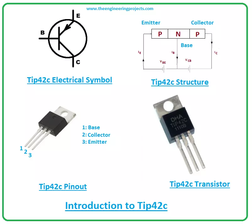
Hi Friends! I welcome you on board. Happy to see you around. In this post, I’ll detail the Introduction to Tip42c. Tip42c is a medium power transistor mainly used for amplification and switching purpose. It is made up of silicon material and falls under the category of PNP transistors. The voltage across collector and emitter terminals is 100V and the voltage across base and collector terminals is 100V. The 5V is the voltage across base and emitter terminals which projects the value of voltage required to bias this transistor. The 6A is collector current which indicates the value of loads this transistor can support. Just bear with me for a little while as I’ll be documenting the main features, pinout, applications, and datasheet of this tiny component Tip42c.

Introduction to TIP42C

  • Tip42c is a PNP medium power bipolar transistor mainly used for switching and amplification purpose.
  • It is composed of silicon material and comes in the TO-220 package.
  • It comes with three pins called the emitter, base, and collector. These pins are also known as transistor terminals that are connected with the external electrical circuit.
  • The small input current across one pair of terminals is used to generate large output current across other pairs of terminals.
  • Tip42c contains three layers where two are p-doped silicon layers and one is an n-doped silicon layer. The n-doped layer represents the base terminal where negative voltage is applied to start the transistor action. The two p-doped layers surround the n-doped layer.
  • As this bipolar transistor controls the small current to produce large current, the reason bipolar transistors are considered as a current-controlled device in contrast to FETs(field effect transistor) which is a unipolar transistor (conductivity happens due to one charge carrier) that are voltage-controlled devices.
  • Two current-gains are important while studying bipolar transistors. One is a common-emitter current gain which ranges from 15 to 75 in this case and common-base current gain which is a ratio between collector current to emitter current, this is normally called alpha.
Its value is always less than 1, commonly lies from 0.90 to 0.95 but more often than not its value is taken as unity.  

TIP42C Features

The following are the main features of device Tip42c
  • Name: TIP42C
  • Package: TO220
  • Material used: Silicon
  • Type: PNP
  • Power Dissipation: 65 W
  • Collector-Base Voltage = Vcb: 100 V
  • Collector-Emitter Voltage = Vce: 100 V
  • Emitter-Base Voltage = Veb: 5 V
  • Collector Current = Ic : 6 A
  • Operating Junction Temperature = Ti:  -65 to 150 °C
  • Transition Frequency = ft: 3 MHz
  • Common-emitter current gain = hfe: 15 to 75
These are the main features and the power ratings of the transistor Tip42c. Don't apply these ratings for more than the desired time, else they will influence the device reliability.
  • The Tip42c is a bipolar transistor which means two charge carriers are used for the conduction process inside the transistor. Both electrons and holes are used for the conductivity, however, holes are the majority carriers and electrons are the minority carriers. Which is the opposite in the case of NPN transistor where electrons are the majority carriers and holes are minority carriers.
  • This PNP transistor comes in TO-220 package with collector current 6A which demonstrates it can support the loads under 6A.
  • The junction temperature ranges from -65 to 150C and the transition frequency is 3MHz which is a measure of the transistor’s high frequency operating characteristics. It is denoted by ft.
  • The common-emitter current gain stands from 15 to 75 which is the capacity of the transistor it can amplify the small input current. It is called beta and is a ratio between output collector current to input base current.
  • And the only 5V is required to start the transistor action because 5V is the voltage across emitter and base terminals.
  • It is important to note that this PNP transistor is not preferred over its counterpart NPN transistor because the mobility of electrons in the NPN transistors is quicker and better than the mobility of holes inside the PNP transistor.
  • Moreover, in NPN transistors the current flows from the collector side to the emitter side in contrast to PNP transistors where current moves from the emitter side to the collector side.
  • The 65W is the power dissipation that indicates the energy released when this transistor starts working in the electrical circuit. This varies from transistor to transistor.

TIP42C Pinout

The Tip42c contains three terminals named: 1: Base 2: Collector 3: Emitter The following diagram shows the pinout of the transistor Tip42c.
  • All these terminals carry different doping concentrations and different working ability. The emitter side is more doped compared to the other two terminals and the collector side is lightly doped. The base side is 10-times more doped than the collector terminals.
  • This bipolar transistor is not symmetrical. This absence of symmetry is due to the different doping concentration of the emitter and collector terminals.
  • In bipolar transistors, the base terminal is responsible for the entire transistor action. When voltage is applied at the base terminal, it gets biased and starts controlling the number of holes in this case of PNP transistors and the number of electrons in the case of NPN transistors.
  • This base terminal acts like a control valve that controls the amount of current. The emitter terminal is highly doped and contains the entire current of the transistor. The emitter current is equal to the sum of the collector current and base current.
 

TIP42C Datasheet

When you’re working with tiny devices like Tip42c, it is wise to scan through the datasheet of the component that documents the main characteristics of the transistor. Click the link below and download the datasheet of Tip42c.

TIP42C Applications

The Tips42c is used in the following applications.
  • Used for switching and amplification applications
  • Used in motor control drivers
  • Employed in H-bridge circuits
  • Incorporated in voltage regulator circuits
  • Used to drive loads under 6A
That’s all for today. I hope you find this article helpful. If you’re unsure or have any question, you can pop your query in the section below, I’d love to help you the best way I can. Feel free to leave your valuable suggestions and feedback, they assist us to generate quality content customized to your exact requirements. Thank you for reading the article.

Application of massage chair STONE TFT LCD with ESP32

Hi Friends! Hope you're well today. I welcome you on board. In this post today, I'll walk you through the application of a massage chair STONE 10.1 inch STVC101WT-01 TFT LCD with ESP32. Let's get started.

Brief Introduction

Massage chair with modern mechanical technology to reproduce the traditional Chinese medicine meridian massage is an important daily health care equipment. The function of the massage chair is to integrate meridian massage of traditional Chinese medicine with modern high-tech means to help users enjoy a comfortable massage, reduce fatigue, and achieve the effect of health care and physical fitness. With the development of single-chip microcomputer intelligent control, a massage chair with a large screen control application is also added. What we need to do here is such an application, select different modes through STONE TFT LCD screen, realize the control of MCU through serial port communication, and then realize the speed and rotation time control of stepping motor by controlling the level of specific IO, to realize the massage function of head and back. The system uses a STONE TFT LCD serial port screen, which can be used to do touch display function. It is very convenient to develop. Only through the serial port can the MCU be controlled. It is used in the massage chair, which can easily realize the setting of a massage function and the adjustment of massage strength, to achieve the effect of self-cultivation and reduce fatigue.

Project Overview

Here we do is a home massage chair application, will STONE TFT After the LCD serial screen is powered on, a start interface will appear. After a short stay, it will jump to a specific interface. This interface is used to set our current time. When setting, a keyboard will pop up. After setting, click OK to enter the massage mode selection interface. Here, I have set three modes: head massage, back massage, and comprehensive mode. In the mode, the massage intensity can be set, the high, middle and low gears can be set, and the corresponding LED light will be used for intensity indication; the massage times can also be set, after reaching the set number, it will automatically stop; in the comprehensive mode, the head and back will be massaged at the same time, and it can be turned off when it is not needed. These actions are through the STONE TFT LCD serial port screen to achieve command transmission.  

The communication functions are as follows:

 
  • ? The serial port screen of STONE TFT LCD realizes the function of button switching interface;
  • ? The serial port screen of STONE TFT LCD realizes the function of an automatic jump when starting up;
  • ? The serial port screen of STONE TFT LCD realizes time setting;
  • ? The serial port screen of STONE TFT LCD realizes data variable distribution;
  • ? STONE TFT LCD serial port screen realizes serial command communication.
  • ? STONE TFT LCD serial port screen realizes the function of menu bar selection;

Modules required for the project:

  • ? STONE TFT LCD;
  • ? Arduino ESP32;
  • ? Stepper motor drive and module;
  • ? LED array module;

Block diagram:

Hardware introduction and principle

STVC101WT-01

  • 10.1 inch 1024x600 industrial grade TFT panel and 4-wire resistance touch screen;
  • brightness is 300cd / m2, LED backlight;
  • RGB color is 65K;
  • visual area is 222.7mm * 125.3mm;
  • visual angle is 70 / 70 / 50 / 60;
  • working life is 20000 hours. 32-bit cortex-m4 200Hz CPU;
  • CPLD epm240 TFT-LCD controller;
  • 128MB (or 1GB) flash memory;
  • USB port (U disk) download;
  • toolbox software for GUI design, simple and powerful hex instructions.

Basic functions

  • Touch screen control / display image / display text / display curve / read and write data / play video and audio. It is suitable for various industries.
  • UART interface is RS232 / RS485 / TTL;
  • voltage is 6v-35v;
  • power consumption is 3.0w;
  • working temperature is - 20 ? / + 70 ?;
  • air humidity is 60 ? 90%.
STVC101WT-01 TFT display module communicates with MCU through a serial port, which needs to be used in this project. We only need to add the designed UI picture through the upper computer through the menu bar options to buttons, text boxes, background pictures, and page logic, then generate the configuration file, and finally download it to the display screen to run. In addition to the data manual, there are user manuals, common development tools, drivers, some simple routine demos, video tutorials, and some for testing projects.

LED array module

Product features

This is a galloping lamp display module with 8 LEDs on board. The external voltage is 3-5.5vdc, and the corresponding LED can be lighted at a low level. It is especially suitable for the IO test of a single chip microcomputer to realize indicator control.

Electrical parameters

  • Working voltage: 3 - 5.5VDC
  • Working current: 24Ma (maximum)
  • Effective level: low level
  • Number of LEDs: 8
  • Display color: red (D1 / D2 / D3 / D4 / D5 / D6 / D7 / D8)
  • It is very suitable for MCU experiment and DIY

ESP32 EVB

Esp32 is a single-chip scheme integrated with 2.4 GHz WiFi and Bluetooth dual-mode. It adopts TSMC's ultra-low power consumption 40 nm technology, with ultra-high RF performance, stability, versatility, and reliability, as well as ultra-low power consumption, which meets different power consumption requirements and is suitable for various application scenarios. At present, the product models of esp32 series include esp32-d0wd-v3, esp32-d0wdq6-v3, esp32-d0wd, esp32-d0wdq6, esp32-d2wd, esp32-s0wd and esp32-u4wdh. Esp32-d0wd-v3, esp32-d0wdq6-v3 and esp32-u4wdh are chip models based on Eco v3.

Wi-Fi

  • 802.11 b/g/n
  • 802.11 n (2.4 GHz) up to 150 Mbps
  • wireless multimedia (WMM)
  • frame aggregation (TX / RX A-MPDU, Rx A-MSDU)
  • immediate block ACK
  • defragmentation
  • beacon automatic monitoring (hardware TSF)
  • 4x virtual Wi-Fi interface

Bluetooth

  • Bluetooth v4.2 complete standard, including traditional Bluetooth (BR / EDR) and low power Bluetooth (BLE)
  • supports standard class-1, class-2, and class-3 without external power amplifier
  • enhanced power control

Output power up to +12 dBm

  • nzif receiver has – 94 DBM ble reception sensitivity
  • adaptive frequency hopping (AFH)
  • standard HCI based on SDIO / SPI / UART interface
  • high-speed UART HCI up to 4 Mbps

Support for Bluetooth 4.2 br / EDR and ble dual-mode controller

  • synchronous connection-oriented/extended synchronous connection-oriented (SCO / ESCO)
  • CVSD and SBC audio codec algorithms
  • piconet and scatternet
  • multi-device connection with traditional Bluetooth and low power Bluetooth
  • support simultaneous broadcast and scanning

ULN2003 Stepper Motor

Product features

ULN2003 is a Darlington display with high voltage and high current. It consists of seven Silicon NPN Darlington tubes. Each pair of Darlington of ULN2003 is connected in series with a 2.7K base resistor. Under 5V working voltage, it can be directly connected with the TTL and CMOS circuit, which can directly process the data that needs a standard logic buffer. Here we use the DIP-16 package, 4-phase 5-wire 5V stepping motor.

Structure and Application

Development steps

Arduino ESP32

Download IDE To complete the code development of esp32, Arduino is used to developing and compiling. First, you need to install the environment and enter the Arduino official website: https://www.arduino.cc/en/Main/Software, and download the version for your platform.

Install Arduino

Double click automatic installation. It should be noted here that Arduino ide relies on the Java development environment and requires PC to install Java JDK and configure variables. If double-click fails to start, it may be that the PC does not have JDK support.

Code

  • HeadGearHigh is used to set the gear to high in receive head mode
  • HeadGearMiddle is used to set the gear to middle in receive head mode
  • HeadGearLow is used to set the gear to low in receive head mode
  • HeadTiming is used to receive the number of times set in head mode
  • HeadModeStart is used to start in receive header mode
  • HeadModeStop is used to stop in receive header mode
  • BackGearHigh is used to set the gear to high in receive back mode
  • BackGearMiddle is used to set the gear to middle in receive back mode
  • BackGearLow is used to set the gear to low in receive back mode
  • BackModeStart is used to start in receive back mode
  • BackModeStop is used to stop in receive back mode
  • IntegratedModeStart is used to receive a start in integrated mode
  • IntegratedModeStop is used to receive stop in integrated mode
After the code is written, we start to compile. After the compilation is successful, download the code to the esp32 EVB board. The operation is as follows:

STONE TOOL 2019

New Project

Find the tool 2019 directory and double-click to open STONE Tool 2019 Click new project and make changes to the resolution, project name, and save path. Then set the boot page, and set the communication packet header: By default, there is a blue back image after a new project is created. Right-click 0.jpg and select remove to delete it. In the same way, select Add to add the image required by the project.

The setting of a selection interface

RTC
To set the time function, first add a clock setting control. Add an RTC control. To make input keyboard, we need to add a button control to each array and give the corresponding key value.

Menu bar selection

Add the menu bar control, set the initial value, and add the corresponding ICO library.

Page jump function

You can set the button effect and the switch page, and the switching interface effect of other buttons is also similar.

Key command setting

Each button needs to be given corresponding action, so the following settings are made: //HEAD uint8_t   HeadGearHigh[9]       = {0xA5, 0x5A, 0x06, 0x83, 0x00, 0x0E, 0x01, 0x00, 0x03}; uint8_t   HeadGearMiddle[9]     = {0xA5, 0x5A, 0x06, 0x83, 0x00, 0x0E, 0x01, 0x00, 0x02}; uint8_t   HeadGearLow[9]        = {0xA5, 0x5A, 0x06, 0x83, 0x00, 0x0E, 0x01, 0x00, 0x01}; uint8_t   HeadTiming[9]         = {0xA5, 0x5A, 0x06, 0x83, 0x00, 0x11, 0x01, 0x00, 0x09}; uint8_t   HeadModeStart[9]    = {0xA5, 0x5A, 0x06, 0x83, 0x00, 0x19, 0x01, 0x41, 0x61}; uint8_t   HeadModeStop[9]     = {0xA5, 0x5A, 0x06, 0x83, 0x00, 0x24, 0x01, 0x46, 0x66};   //BACK uint8_t   BackGearHigh[9]       = {0xA5, 0x5A, 0x06, 0x83, 0x00, 0x1A, 0x01, 0x00, 0x01}; uint8_t   BackGearMiddle[9]     = {0xA5, 0x5A, 0x06, 0x83, 0x00, 0x1A, 0x01, 0x00, 0x02}; uint8_t   BackGearLow[9]      = {0xA5, 0x5A, 0x06, 0x83, 0x00, 0x1A, 0x01, 0x00, 0x03};   uint8_t   BackModeStart[9]      = {0xA5, 0x5A, 0x06, 0x83, 0x00, 0x0C, 0x01, 0x42, 0x62}; uint8_t   BackModeStop[9]     = {0xA5, 0x5A, 0x06, 0x83, 0x00, 0x0D, 0x01, 0x43, 0x63};   //Integrated uint8_t   IntegratedModeStart[9]= {0xA5, 0x5A, 0x06, 0x83, 0x00, 0x0F, 0x01, 0x44, 0x64}; uint8_t   IntegratedModeStop[9] = {0xA5, 0x5A, 0x06, 0x83, 0x00, 0x1F, 0x01, 0x45, 0x65};  

Connection

Code

/* Stepper Motor Control - one revolution This program drives a unipolar or bipolar stepper motor. The motor is attached to digital pins 8 - 11 of the Arduino. The motor should revolve one revolution in one direction, then one revolution in the other direction. Created 11 Mar. 2007 Modified 30 Nov. 2009 by Tom Igoe */ //#include <Stepper.h> #include "stdlib.h" #include <AccelStepper.h> const float STEPCYCLE = 2050;//A Cycle by Step is 2050; //  myStepper.setSpeed(100);//5V, it can be set up to 180 const float TheMaxSpeed = 1000.0;  // change this to fit the number of steps per revolution const float headspeed_str[4] = { 0, TheMaxSpeed / 4, TheMaxSpeed / 2, TheMaxSpeed, }; const float backspeed_str[4] = { 0, TheMaxSpeed, TheMaxSpeed / 2, TheMaxSpeed / 4, }; // for your motor // initialize the stepper library on pins 8 through 11: AccelStepper HeadStepper(AccelStepper::FULL4WIRE, 15, 0, 2, 4);//The middle two IO are reversed AccelStepper BackStepper(AccelStepper::FULL4WIRE, 16, 5, 17, 18);//The middle two IO are reversed const int ledPin_1 =  14;      // the number of the LED pin const int ledPin_2 =  27;      // the number of the LED pin const int ledPin_3 =  26;      // the number of the LED pin const int ledPin_4 =  25;      // the number of the LED pin const int ledPin_5 =  33;      // the number of the LED pin const int ledPin_6 =  21;      // the number of the LED pin const int ledPin_7 =  22;      // the number of the LED pin const int ledPin_8 =  23;      // the number of the LED pin //buf uint8_t   cout_i = 0; uint8_t   RecievedTemp[9]       = {0}; float     settingbuf[2]       = {TheMaxSpeed, 0}; float   MorenCycle      = 100; //HEAD uint8_t   HeadGearHigh[9]       = {0xA5, 0x5A, 0x06, 0x83, 0x00, 0x0E, 0x01, 0x00, 0x03}; uint8_t   HeadGearMiddle[9]     = {0xA5, 0x5A, 0x06, 0x83, 0x00, 0x0E, 0x01, 0x00, 0x02}; uint8_t   HeadGearLow[9]        = {0xA5, 0x5A, 0x06, 0x83, 0x00, 0x0E, 0x01, 0x00, 0x01}; uint8_t   HeadTiming[9]         = {0xA5, 0x5A, 0x06, 0x83, 0x00, 0x11, 0x01, 0x00, 0x09}; uint8_t   HeadModeStart[9]    = {0xA5, 0x5A, 0x06, 0x83, 0x00, 0x19, 0x01, 0x41, 0x61}; uint8_t   HeadModeStop[9]     = {0xA5, 0x5A, 0x06, 0x83, 0x00, 0x24, 0x01, 0x46, 0x66}; //BACK uint8_t   BackGearHigh[9]       = {0xA5, 0x5A, 0x06, 0x83, 0x00, 0x1A, 0x01, 0x00, 0x01}; uint8_t   BackGearMiddle[9]     = {0xA5, 0x5A, 0x06, 0x83, 0x00, 0x1A, 0x01, 0x00, 0x02}; uint8_t   BackGearLow[9]      = {0xA5, 0x5A, 0x06, 0x83, 0x00, 0x1A, 0x01, 0x00, 0x03}; uint8_t   BackModeStart[9]      = {0xA5, 0x5A, 0x06, 0x83, 0x00, 0x0C, 0x01, 0x42, 0x62}; uint8_t   BackModeStop[9]     = {0xA5, 0x5A, 0x06, 0x83, 0x00, 0x0D, 0x01, 0x43, 0x63}; //Integrated uint8_t   IntegratedModeStart[9]= {0xA5, 0x5A, 0x06, 0x83, 0x00, 0x0F, 0x01, 0x44, 0x64}; uint8_t   IntegratedModeStop[9] = {0xA5, 0x5A, 0x06, 0x83, 0x00, 0x1F, 0x01, 0x45, 0x65}; void setup() { //Serial port initialization Serial.begin(115200); //The motor starts running separately //  HeadStepper_Setting_Run(TheMaxSpeed, 5); //  BackStepper_Setting_Run(TheMaxSpeed, 5); // initialize the LED pin as an output: pinMode(ledPin_1, OUTPUT); pinMode(ledPin_2, OUTPUT); pinMode(ledPin_3, OUTPUT); pinMode(ledPin_4, OUTPUT); pinMode(ledPin_5, OUTPUT); pinMode(ledPin_6, OUTPUT); pinMode(ledPin_7, OUTPUT); pinMode(ledPin_8, OUTPUT); digitalWrite(ledPin_1, HIGH);   // turn the LED on (HIGH is the voltage level) digitalWrite(ledPin_2, HIGH);  // turn the LED on (HIGH is the voltage level) digitalWrite(ledPin_3, HIGH);  // turn the LED on (HIGH is the voltage level) digitalWrite(ledPin_4, HIGH);  // turn the LED on (HIGH is the voltage level) digitalWrite(ledPin_5, HIGH);  // turn the LED on (HIGH is the voltage level) digitalWrite(ledPin_6, HIGH);  // turn the LED on (HIGH is the voltage level) digitalWrite(ledPin_7, HIGH);  // turn the LED on (HIGH is the voltage level) digitalWrite(ledPin_8, HIGH);  // turn the LED on (HIGH is the voltage level) } void loop() { if(Serial.available() != 0) { for(cout_i = 0; cout_i < 9; cout_i ++) { RecievedTemp[cout_i] = Serial.read(); } //    if(HeadStepper.isRunning() == true) //    { //      HeadStepper.stop(); //    } //    if(BackStepper.isRunning() == true) //    { //      BackStepper.stop(); //    } //  else //  { //    Stepper2_Setting_Run(TheMaxSpeed, 5); //  } //  Serial.write(RecievedTemp, 9); switch(RecievedTemp[5]) { case 0x0E://head gear if(HeadStepper.isRunning() == true) { HeadStepper.stop(); } settingbuf[0] = headspeed_str[RecievedTemp[8]]; if(RecievedTemp[8] == 1) { digitalWrite(ledPin_1, LOW);   // turn the LED on (HIGH is the voltage level) digitalWrite(ledPin_2, LOW);   // turn the LED on (HIGH is the voltage level) digitalWrite(ledPin_3, LOW);   // turn the LED on (HIGH is the voltage level) digitalWrite(ledPin_4, HIGH);   // turn the LED on (HIGH is the voltage level) digitalWrite(ledPin_5, HIGH);   // turn the LED on (HIGH is the voltage level) digitalWrite(ledPin_6, HIGH);   // turn the LED on (HIGH is the voltage level) digitalWrite(ledPin_7, HIGH);   // turn the LED on (HIGH is the voltage level) digitalWrite(ledPin_8, HIGH);   // turn the LED on (HIGH is the voltage level) } else if(RecievedTemp[8] == 2) { digitalWrite(ledPin_1, LOW);   // turn the LED on (HIGH is the voltage level) digitalWrite(ledPin_2, LOW);   // turn the LED on (HIGH is the voltage level) digitalWrite(ledPin_3, LOW);   // turn the LED on (HIGH is the voltage level) digitalWrite(ledPin_4, LOW);   // turn the LED on (HIGH is the voltage level) digitalWrite(ledPin_5, LOW);   // turn the LED on (HIGH is the voltage level) digitalWrite(ledPin_6, LOW);   // turn the LED on (HIGH is the voltage level) digitalWrite(ledPin_7, HIGH);   // turn the LED on (HIGH is the voltage level) digitalWrite(ledPin_8, HIGH);   // turn the LED on (HIGH is the voltage level) } else { digitalWrite(ledPin_1, LOW);   // turn the LED on (HIGH is the voltage level) digitalWrite(ledPin_2, LOW);   // turn the LED on (HIGH is the voltage level) digitalWrite(ledPin_3, LOW);   // turn the LED on (HIGH is the voltage level) digitalWrite(ledPin_4, LOW);   // turn the LED on (HIGH is the voltage level) digitalWrite(ledPin_5, LOW);   // turn the LED on (HIGH is the voltage level) digitalWrite(ledPin_6, LOW);   // turn the LED on (HIGH is the voltage level) digitalWrite(ledPin_7, LOW);   // turn the LED on (HIGH is the voltage level) digitalWrite(ledPin_8, LOW);   // turn the LED on (HIGH is the voltage level) } break; case 0x11://head timing if(HeadStepper.isRunning() == true) { HeadStepper.stop(); } settingbuf[1] = RecievedTemp[8]; break; case 0x19://head start if(settingbuf[1] == 0) { settingbuf[1] = 5; } break; case 0x24://head stop if(HeadStepper.isRunning() == true) { HeadStepper.stop(); } break;   case 0x1A://backgear if(BackStepper.isRunning() == true) { BackStepper.stop(); } settingbuf[0] = backspeed_str[RecievedTemp[8]]; if(RecievedTemp[8] == 3) { digitalWrite(ledPin_1, LOW);   // turn the LED on (HIGH is the voltage level) digitalWrite(ledPin_2, LOW);   // turn the LED on (HIGH is the voltage level) digitalWrite(ledPin_3, LOW);   // turn the LED on (HIGH is the voltage level) digitalWrite(ledPin_4, HIGH);   // turn the LED on (HIGH is the voltage level) digitalWrite(ledPin_5, HIGH);   // turn the LED on (HIGH is the voltage level) digitalWrite(ledPin_6, HIGH);   // turn the LED on (HIGH is the voltage level) digitalWrite(ledPin_7, HIGH);   // turn the LED on (HIGH is the voltage level) digitalWrite(ledPin_8, HIGH);   // turn the LED on (HIGH is the voltage level) } else if(RecievedTemp[8] == 2) { digitalWrite(ledPin_1, LOW);   // turn the LED on (HIGH is the voltage level) digitalWrite(ledPin_2, LOW);   // turn the LED on (HIGH is the voltage level) digitalWrite(ledPin_3, LOW);   // turn the LED on (HIGH is the voltage level) digitalWrite(ledPin_4, LOW);   // turn the LED on (HIGH is the voltage level) digitalWrite(ledPin_5, LOW);   // turn the LED on (HIGH is the voltage level) digitalWrite(ledPin_6, LOW);   // turn the LED on (HIGH is the voltage level) digitalWrite(ledPin_7, HIGH);   // turn the LED on (HIGH is the voltage level) digitalWrite(ledPin_8, HIGH);   // turn the LED on (HIGH is the voltage level) } else { digitalWrite(ledPin_1, LOW);   // turn the LED on (HIGH is the voltage level) digitalWrite(ledPin_2, LOW);   // turn the LED on (HIGH is the voltage level) digitalWrite(ledPin_3, LOW);   // turn the LED on (HIGH is the voltage level) digitalWrite(ledPin_4, LOW);   // turn the LED on (HIGH is the voltage level) digitalWrite(ledPin_5, LOW);   // turn the LED on (HIGH is the voltage level) digitalWrite(ledPin_6, LOW);   // turn the LED on (HIGH is the voltage level) digitalWrite(ledPin_7, LOW);   // turn the LED on (HIGH is the voltage level) digitalWrite(ledPin_8, LOW);   // turn the LED on (HIGH is the voltage level) } break; case 0x0C://backstart BackStepper_Setting_Run(settingbuf[0], MorenCycle); break; case 0x0D://backstop if(BackStepper.isRunning() == true) { BackStepper.stop(); } break; case 0x0F://integratestart if(HeadStepper.isRunning() == true) { HeadStepper.stop(); } if(BackStepper.isRunning() == true) { BackStepper.stop(); } break; case 0x1F://integratedstop if(HeadStepper.isRunning() == true) { HeadStepper.stop(); } if(BackStepper.isRunning() == true) { BackStepper.stop(); } break; default: break; } //    Serial.write(&Targetvalue, 1); //    Serial.print(Targetvalue); } }

Application of massage chair Appendix

That's all for today. I hope you find this post helpful. If you have any question, you can approach me in the section below, I'd love to help you the best way I can. Thank you for reading the article.
Syed Zain Nasir

I am Syed Zain Nasir, the founder of <a href=https://www.TheEngineeringProjects.com/>The Engineering Projects</a> (TEP). I am a programmer since 2009 before that I just search things, make small projects and now I am sharing my knowledge through this platform.I also work as a freelancer and did many projects related to programming and electrical circuitry. <a href=https://plus.google.com/+SyedZainNasir/>My Google Profile+</a>

Share
Published by
Syed Zain Nasir