Hi Friends! Hope you’re well today. Happy to see you around. In this post, I’ll detail the Introduction to Arduino UNO REV3.
Arduino Uno REV 3 is an Arduino board based on the microcontroller ATmega328P. It carries 14 digital I/O pins out of which 6 can be used as PWM outputs. Moreover, 6 analog input pins are available on the board and the clock frequency is 16MHz.
Arduino UNO is one of the most used boards from the Arduino family. The robust and clean design helps you shape your ideas into reality.
Know that Arduino UNO REV3 is an advanced version of Arduino UNO. The new version includes four solder pads JP2 attached with the pins PB4 to PB7 of the USB ATmega.
Uno stands for one in Italian and this name was picked for the release of Arduino ...
Hello Buddies, Welcome from the team of The Engineering Projects. We hope you are having a good day. In this article, you will investigate about four remarkable tips for a better job bit that will boost your chances to be hired.
Construction is an emerging and fast-growing source of business. However, we cannot neglect that it is a very competitive field at the same time.
In this ever-growing world, where the construction business is highly profitable and demanding, most people fail to get better construction jobs due to inaccurate bids. While construction bidding is not an easy task, better understanding and farsightedness can help you win more jobs.
What is construction bidding?
Construction bidding is the process through which you submit a pro ...
Hello Learners! welcome from the team of The Engineering Projects. We hope you are having a productive day. We are working on a series of Blogs based upon the core knowledge about Digital Logic Gates and Circuits. In this tutorial, we'll know about the SR Flip Flops and after brief introduction we will simulate SR Flip Flops in Proteus. Let's have a glimpse on the topics of today:
What are Flip Flops?
What are the types of Flip Flop?
How does we design the Truth Table of SR Flip Flops?
What are further classes of SR Flip Flips?
Implementation of SR Flip Flops in Proteus.
Flip Flops
Flip Flops are extremely important Circuits of Digital Logic Design. We Introduce the Flip Flops as:
"Flip Flops are type of sequential Logic Circuit that co ...
Hello Everyone! Hope you’re well today. Happy to see you around. In this post today, I’ll walk you through the Introduction to Arduino Uno WiFi Rev 2.
Arduino Uno WiFi Rev 2 is a microcontroller board based on ATmega4809 and carries an ECC608 crypto chip to ensure a secure and safe WiFi connection. The board contains 14 digital I/O pins, 5 PWM pins, 6 analog pins, one SPI protocol, one I2C, and one UART communication protocol.
I suggest you read this entire post till the end as I’ll detail the complete Introduction to Arduino Uno WiFi Rev2 covering pinout, pin description, features, programming, and applications.
Let’s jump right in.
Introduction to Arduino Uno WiFi Rev 2
The Arduino Uno WiFi Rev 2 is a microcontroller board that is mainly ...
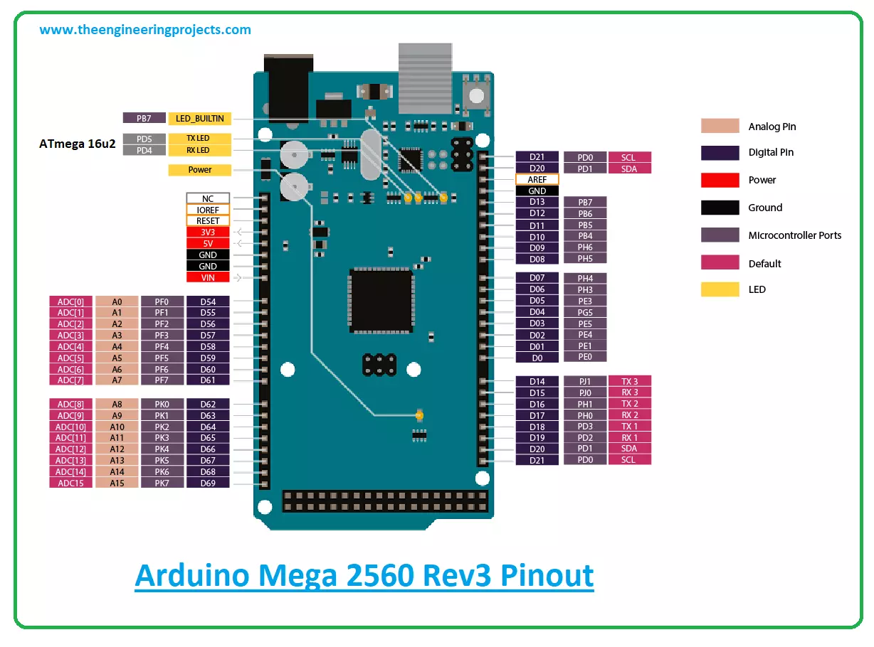
Hi Friends! Hope you’re well today. In this post today, I’ll walk you through the detailed Introduction to Arduino Mega 2560 Rev3.The Arduino Mega 2560 Rev3 is a microcontroller board that is based on the ATmega2560 microcontroller.
The Arduino boards are widely used in the automation industry and embedded projects. Other boards like Arduino Uno, Arduino Nano, Arduino Every, Arduino Beetle all seem a good pick for the projects that require little memory to store the program. However, when the nature of projects becomes complex, requiring more memory and a rich set of I/O interfaces, the Arduino Mega 2560 Rev3 comes into play. In order to power up these Arduino boards, we need to use a Power supply for electronics or we can also use the USB port on ...
Learning Management Systems have gained popularity with technological advancements.
The curiosity to learn NEW made the information available with just a few clicks away. That’s how e-learning was born!
Now, it has become inevitable for every business to adapt to the trend. When it involves developing a course from scratch, you need LMS.
Well, by what norms do we identify LMS vendors for my business?
Here are five checkpoints you should know when choosing an LMS vendor.
The background
It is quite common when you are choosing an LMS vendor; you look for the price. Beyond the quote they are offering, you need to verify their track record.
Ask the following questions to acquire the vendor’s level of the business.
How long has the LMS d ...