ESP32 Web Server in Access Point (AP) Mode

Hello readers, hope you all are doing great. This is our 3rd tutorial in the ESP32 programming series. In our previous tutorial, we discussed the ESP32 Web server, where we created the ESP32 web server in STA mode.

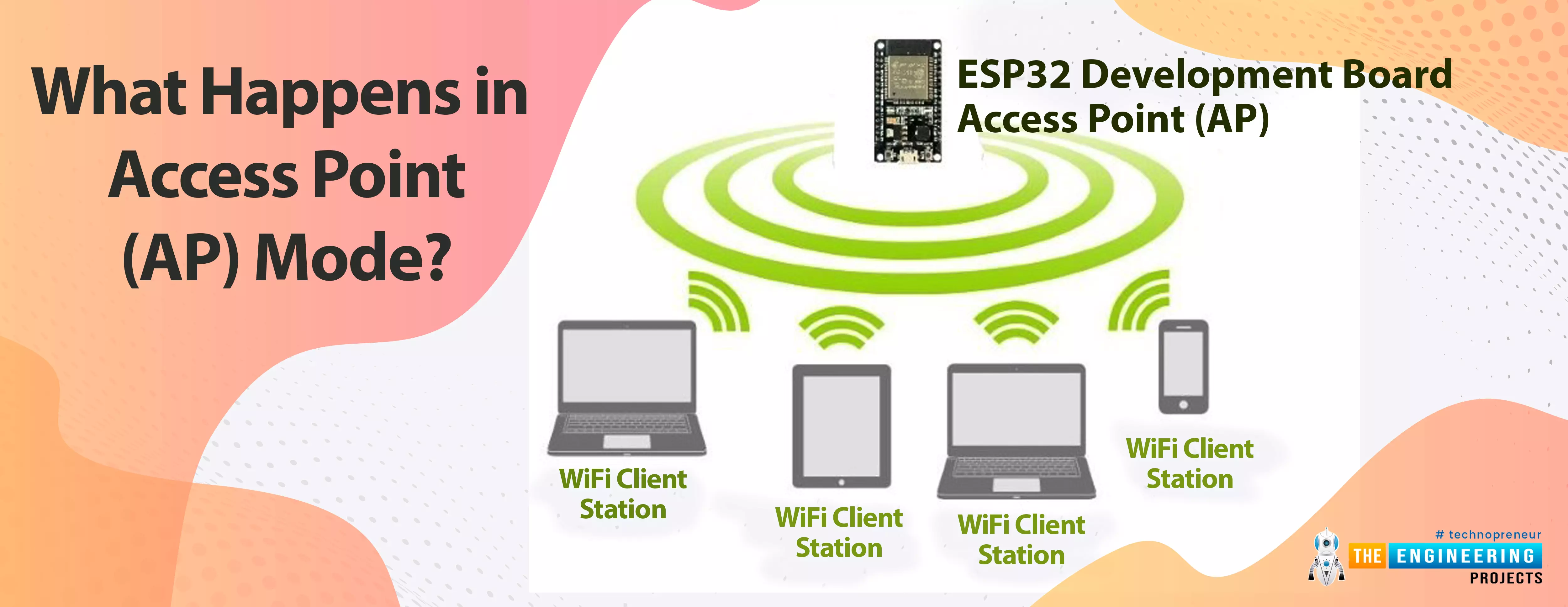
ESP32 can be operated as an access point (AP) or a Wi-Fi station (STA mode). So, in this tutorial, we will create an ESP32 web server in access point (AP) mode. Here's the video demonstration of ESP32 WebServer in Access Point Mode:

As I mentioned above, in our 2nd tutorial, we already discussed the basics of the ESP32 web server. So, in this tutorial, we will only discuss how to create the ESP32 in access point mode.

For detailed information about the basics of the ESP32 web server and how client-server communication takes place, follow our previous tutorial (i.e., Create a Web Server with ESP32).

Where To Buy?
No.ComponentsDistributorLink To Buy
1ESP32AmazonBuy Now

What happens in Access Point (AP) mode?

In Access Point Mode the ESP32 creates its own wireless Wi-Fi network in this mode, similar to the one provided by your existing router. In access point mode, we don't need to connect the ESP2 to a Wi-Fi network. In the Wi-Fi network it creates, the ESP32 Wi-Fi board can connect up to 5 devices.

Fig 1 ESP32 as an Access Point

So, in access point mode, nearby Wi-Fi devices such as mobile phones, laptops, or a secondary ESP32 module acting as a station can connect directly to the AP (ESP32 module) without the need for an external Wi-Fi router.

On the other hand, in Station mode, the ESP32 wi-fi module connects to your Wi-Fi network through a router. The router acts as a conduit for communication between the web client and the ESP32. The Wi-Fi router provides the IP address. This IP address can be used by web clients to connect to the Web server on a local network.

To know about how to set up/operate Arduino IDE for ESP32 compilation, follow our first tutorial i.e., Introduction to ESP32 programming series.

ESP32 Web Server in Access Point (AP) Mode

Here we are using an inbuilt example from Arduino IDE(ESP32). You can modify the example code as per your requirements or can write your own code.

  • To find the Wi-Fi Access Point example in Arduino IDE :
  • Click on File from the top menu bar.
  • Place the mouse cursor on the example option from the list.
  • Look for the WiFi option.
  • There you will find the WiFiAccessPoint option, click on that and compile the program.

A screenshot is attached below to help you find the example code in Arduino IDE.

Fig 2 Wi-Fi access point example

The first task while writing the WiFi code is to add the required wifi header files or libraries in the code.

Here we are adding three libraries.

  • WiFi.h: This header file contains all the functions related to Wi-Fi activities like enabling the Wi_Fi, connecting to a wi-fi network etc.
  • WiFiClient.h: This header file is used to create a client that can connect with a specific IP address.
  • WiFiAP.h: This header file is used to configure and manage ESP32’s wifi module in Access Point (AP) mode.

Fig 3: Libraries

Define the LED pin or a GPIO (for peripheral interface) which we going to control through web server. Here we are using the inbuilt LED which is internally connected with GPIO2

Give a name (SSID) to the ESP32 Access Point and set the password for security purpose ( if you wish to).

While creating a web server we also need to assign a port and usually port 80 is used for local web server.

Arduino Setup() function

Inside the setup function, the LED pin is initialized as an output one and then initialized the serial monitor with a baud rate of 115200.

The next task is to configure the ESP32 Wi-Fi module in access point mode. For that, here we are calling a function called WiFi.softAP. Where we are passing two parameters, ssid and password, respectively.

After configuring the AP mode, we need to fetch the IP address of the access point by calling the WiFi.softAPIP() function and printing it on the serial monitor.

Then, after fetching the IP address, we will start the server using the server. perform.

Arduino Loop() function

After configuring the Access Point mode and initializing the server, the server will next wait for the station or client connection, which can be a mobile phone, a laptop, or another ESP32 board configured in STA mode.

Once the connection is established between the access point and the client device, the access point will wait for the data input.

A string type variable called currentLine has been defined to hold the incoming data from the client.

If there is a byte to be read from the client, then it will be stored inside the char type variable c.

HTTP header always starts with a response code e.g.: HTTP/1.1 200 ok

An HTML page will be created on the client’s browser, from where the client device can control (ON/OFF) the LED.

Different URLs will be created to turn ON and OFF the LED depending upon the HTML input received from the client device i.e., H (to turn ON the LED) and L ( to turn OFF the LED).

Client.stop() function is responsible for closing the connection between Access Point and client or station device.

Note: If you need any guidance regarding how to upload or compile a code for the ESP32 module in Arduino IDE, follow our first tutorial on the ESP32 programming series.

Testing ESP32 web server with hardware in Access Point with Arduino IDE

Here we are going to control the ESP32’s inbuilt LED through an ESP32 web server (AP mode).

We will connect our station or client device through Wi-Fi to the ESP32 module, which (ESP32) is currently acting as an access point (AP).

To establish the connection go to your mobile phone’s Wi-Fi setting.

The Access Point is advertising itself with a pre-defined SSID so that the station devices or clients can find the AP device and can communicate with each other.

If you find a wi-fi device (AP) named ESP32_AP (or as per your SSID) connect to that after entering the assigned password.

Fig. Scanning for available Wi-Fi devices in mobile phone

Fig. Connected with ESP32 AP

As we are using the inbuilt LED, no external components are required.

After connecting to the access point, you can find the IP address of the AP device printed on the Serial Monitor. As shown in the image below:

Fig.: Serial Monitor

Enter the IP address in the browser. Now you can turn the LED ON or OFF using the web page as shown in the images below.

A web page with URL 192.168.4.1/H will be displayed on the browser when LED is turned ON

Fig.: URL when LED is turned ON

LED is blue color represents the inbuilt LED which is connected to GPIO_2.

Fig.: ESP32 LED ON

Another web page with URL 192.168.4.1/L will be created when the AP will receive the input to turn OFF the inbuilt LED. As shown in the image below:

Fig.: Web page displaying the LED off state.

This concludes today’s tutorial. We hope you find it helpful.

In our next tutorial, we will discuss another ESP32 feature that is BLE (Bluetooth low energy).

ESP32 Bluetooth Classic in Arduino IDE

Hello readers, I hope you all are doing well. Welcome to the Section 2 (ESP32 Features) of the ESP32 Programming Series. ESP32 is equipped with numerous built-in features and in each chapter of this Section 2, we will explore one of these ESP32 features in detail.

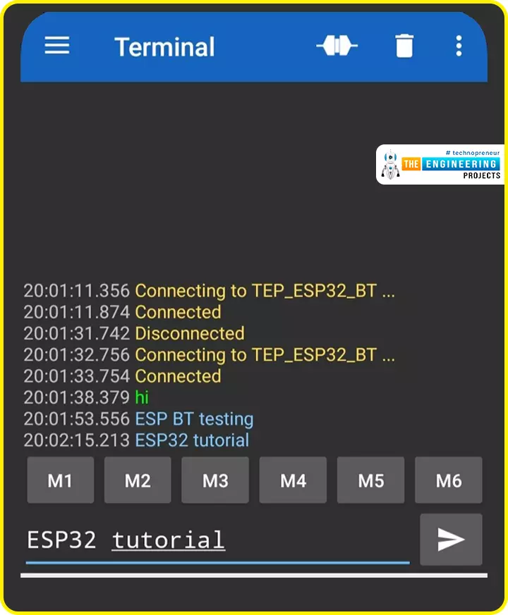
In the previous Section(Section 1: ESP32 IDEs), we installed different software IDEs to program ESP32 boards. Among these IDEs, we are going to use Arduino IDE for programming ESP32. So, I hope all of your tools are configured properly and you are ready to explore the built-in features of ESP32.

Today's the 1st Chapter of Section 2, and here we will discuss How to communicate with ESP32 Bluetooth Classic from a smartphone using Arduino IDE.

Here's the video tutorial for ESP32 Bluetooth Classic:

Where To Buy?
No.ComponentsDistributorLink To Buy
1ESP32AmazonBuy Now

ESP32 Wireless Features

ESP32 is equipped with 3 wireless communication protocols:

  • Bluetooth Classic
  • Bluetooth Low Energy(BLE)
  • Wi-Fi

Before going forward, let's first have a look at the basic features of BT Classic:

What is Bluetooth Classic?

Bluetooth is a short-range communication(wireless) technology, used in electronic devices(i.e. mobile phones, computers, LED, headphones, speakers etc.) for wireless communication over a short distance, approximately 15m. Bluetooth operates at a 2.4GHz ISM band. Bluetooth uses low-energy radio waves for data communication between Bluetooth-enabled devices.

Now, let's design the code to communicate over ESP32 Classic BT:

ESP32 Bluetooth Classic

We are using Arduino IDE for code compiling and uploading to the ESP32 module. I hope you have already installed ESP32 Boards in Arduino IDE. So, let's design a simple project to understand the working of ESP32 Bluetooth Classic:

Project Description

First of all, we will install a "Serial BluetoothTerminal" App from the Google Play Store to communicate with the ESP32 Classic BT.

In this project, we will first enable the ESP32 Classic Bluetooth, so that we can connect it to our smartphone. After a successful connection, we will send data from our smartphone(Serial Bluetooth Terminal App) to the ESP32 Serial Terminal and vice versa.

So, let's first understand the ESP32 BT Code and then will install the Serial Bluetooth App from the Google Play Store:

Code for ESP32 Classic BT

  • Open Arduino IDE and navigate to "File > Examples > BluetoothSerial > SerialtoSerialBT".
  • This code utilizes BluetoothSerial Library, it's pre-installed with Arduino IDE but if you can't find it in the Examples, you can manually Download Bluetooth Serial Library and add it from Library Manager in Arduino IDE.
  • Upload this code to your ESP32 Microcontroller Board.

Here's the complete code:

    #include "BluetoothSerial.h"
    #if !defined(CONFIG_BT_ENABLED) || !defined(CONFIG_BLUEDROID_ENABLED)
    #error Bluetooth is not enabled! Please run `make menuconfig` to enable it
    #endif
    
    BluetoothSerial SerialBT;
    
    void setup() {
        Serial.begin(115200);
        SerialBT.begin("TEP_ESP32_BT"); //Bluetooth device name
        Serial.println("The device started, now you can pair it with bluetooth!");
    }
    
    void loop() {
        if (Serial.available()) {
            SerialBT.write(Serial.read());
        }
        if (SerialBT.available()) {
            Serial.write(SerialBT.read());
        }
    
        delay(20);
    }
    

    Let's understand the code working:

    How the Code Works

    • First of all, we added the Classic Bluetooth Library named "BluetoothSerial", it has all the routines/functions required to enable Bluetooth and to communicate with other devices.
    #include "BluetoothSerial.h"
    
    • Next, we placed a check to ensure that Classic Bluetooth is configured properly and is discoverable to other devices:
    #if !defined(CONFIG_BT_ENABLED) || !defined(CONFIG_BLUEDROID_ENABLED)
    #error Bluetooth is not enabled! Please run `make menuconfig` to enable it
    #endif
    
    • Next, we created a Bluetooth object "SerialBT" of class BluetoothSerial to initialize the Bluetooth stack and communicate serially with ESP32 Classic Bluetooth:
    BluetoothSerial SerialBT;
    

    Setup() Function

    Initial Configurations of the project are added in the Setup() function. In our code:

    • First, we initialized the Serial Port at a baud rate of 115200.
    • Next, we initialized the SerialBT object and assigned a unique name "TEP_ES32_BT" to our Bluetooth device, this name will appear in the Bluetooth Search List.
    • Finally, printed a welcome message on the Serial Monitor.
    void setup() {
        Serial.begin(115200);
        SerialBT.begin("TEP_ESP32_BT"); //Bluetooth device name
        Serial.println("The device started, now you can pair it with bluetooth!");
    }
    

    Loop() Function

    The Loop() Function is an infinite loop and is equivalent to while(1) in normal C Language. In our code, we have placed two if checks:

    • The first "IF Check" is monitoring the ESP32 Serial Terminal.

    If we send any data from the Serial Terminal, this data will be transmitted to the SerialBT.

    • The second "IF Check" is monitoring the SerialBT.

    If we receive any data via ESP32 Classic Bluetooth, we will print it on the Serial Terminal.

    void loop() {
        if (Serial.available()) {
            SerialBT.write(Serial.read());
        }
        if (SerialBT.available()) {
            Serial.write(SerialBT.read());
        }
    
        delay(20);
    }
    

    So, I hope you have understood the working of this ESP32 Classic Bluetooth code. Now, let's install the Serial Bluetooth Terminal App from the Google Play Store:

    Serial Bluetooth Terminal App

    • Make sure your mobile's Bluetooth is enabled.
    • Open the Google Play Store on your Smartphone and make a search for "Serial Bluetooth Terminal" and install it.

    If we are connecting with the ESP32 BT for the first time, we need to pair it first.

    • Open the Serial Bluetooth Terminal app and click on the "Devices" tab.

    It will scan the list of all the available Bluetooth devices:

    [Image]

    • Now, Pair with the ESP32 Classic BT device named "TEP_ESP32_BT".
    • Click on Pair.

    We have successfully paired the ESP32 BT with the smartphone's Bluetooth.

    ESP32 BT to Smartphone - Data Testing

    • Open the Bluetooth Terminal App and click on the Connect Button at the top:

    [Image]

    • Open the Serial Monitor in the Arduino IDE and set the baud rate to 115200:

    [Image]

    • As shown in the below figure, when we send data from the Serial Monitor, it communicates over Classic Bluetooth and appears in the BT Terminal App.
    • Similarly, when we send data from the BT Terminal App, it appears on the Serial Monitor of Arduino IDE.

    So, that's how we can communicate between ESP32 and smartphones over Classic Bluetooth. In today's lecture, we communicated simple text data to understand the working principle. In the upcoming lectures, we will send complex data(i.e. commands & sensor values) via Classic Bluetooth.

    Now, let's have a look at some theoretical knowledge about Classic Bluetooth:

    BLE vs Bluetooth Classic

    Fig: BLE vs Classic Bluetooth

    • Bandwidth: Bluetooth can send a large amount of data, while BLE sends small chunks of data.
    • Compatibility: Classic Bluetooth and BLE are not compatible with each other. A Bluetooth-supported device can’t communicate with BLE supported device.

    But, a device having BT V4 (Bluetooth version 4) can discover both BLE and Classic Bluetooth devices.

    • Power consumption: The classic Bluetooth consumes more power than BLE.
    • Pairing: In Bluetooth classic pairing is necessary before sharing data between Bluetooth devices for security purposes. On the other hand, BLE technology doesn't ask for pairing before data transmission.
    • Number of active devices: In traditional Bluetooth, a maximum of 7 slave devices can be connected with the master Bluetooth at a time. Though classic Bluetooth can connect with multiple nodes/slave devices at a time but it can exchange data with only a single node at a time.

    Bluetooth Evolution

    • The initial Bluetooth version (V1.0) was riddled with bugs and limitations.
    • Bluetooth 2.0 was created as a result of various modifications and improvements to the basic version 1.0.
    • Bluetooth 2.0's most notable feature was the enhanced data rate (EDR).
    • Fast modulation technology and a data rate of up to 3Mbps are used in Enhanced Data Rate mode.
    • Despite improvements in the basic version, Bluetooth 2.0 lacks a security feature.
    • Bluetooth 2.1 added a security feature called "Pairing" as well as a faster data rate.
    • Another updated version, Bluetooth 3.0, included a Wi-Fi feature, but it was rarely used, and when it was, the features were similar to the Bluetooth 2.1 version.
    • Bluetooth 4.0 was the first version to include the Bluetooth low energy feature (BLE).
    • The most recent Bluetooth version is v5.2, which supports both Classic Bluetooth and BLE and consists of the following features:
    1. EATT (enhanced attribute protocol)
    2. LE (Low Energy) power control feature (LEPCF)
    3. LE Audio

    Bluetooth Network topology

    • Classic Bluetooth forms a piconet. A piconet has a single master and multiple(max 7) slaves. Each piconet has its own hopping sequence.

    Fig: Classic Bluetooth Network topology

    Classic Bluetooth can operate on both point-to-point and point-to-multi-point network topology. In traditional Bluetooth, a maximum of 7 slave devices can be connected with the master Bluetooth at a time. Though, classic Bluetooth can connect with multiple nodes/slave devices at a time, but it can exchange data with only a single node at a time.

    Bluetooth Clock

    In classic Bluetooth, the piconets are not synchronized.

    The clock is one of the most important aspects of Bluetooth. In a Bluetooth connection, the master device has a clock that is used to split the time on each physical channel. Clocks on all slaves in a connection are synchronized to the master clock.

    Bluetooth clock synchronization is essential because the radios must agree on when to transmit. Because Bluetooth uses precise timeslots for transmissions with devices alternating, if the clocks are not synchronized, there may be issues with devices transmitting at the incorrect time.

    Classic Bluetooth transmitting power

    It is defined in multiple classes:

    • Class 1: +20dBm maximum.
    • Class 2: Up to +4dBm.
    • Class 3: Up to +0dBm.

    Classic Bluetooth Data transmission modes

    Generally, there are two data transmission modes:

    1. Basic Rate (BR): BR is the first Bluetooth protocol which is implemented in Bluetooth v1.0. It uses one of the FSK (frequency shift keying) modulation techniques known as Gaussian frequency-shift keying (GFSK) and communicates data at the 2.4 GHz ISM band.
    2. Enhanced Data Rate (EDR): It's a Bluetooth specification that allows for a higher data rate or speed. It is not available in all Bluetooth versions, and its availability is dependent on the Bluetooth version and profile. EDR uses pi/4-DQPSK (differential quadrature phase-shift keying) and 8DPSK (differential phase-shift keying) modulation techniques with data rates of 2Mbps and 3Mbps respectively.

    Bluetooth packet format

    • When two devices communicate data over Classic Bluetooth, they use SPP (Serial Port Profile)

    Fig. Bluetooth packet format

    Enhanced data rate packet sends the Access code and header using the basic rate and this process uses GFSK (Gaussian Frequency Shift Keying). The guard gives the time to change the modulation to EDR modulation and then the synch word (64 bits), payload, and Trailer (4 bits) bits are sent using EDR (enhanced data rate) modulation.

    So, that was all for today. In the next lecture, we will communicate between ESP32 and smartphones via BLE(Bluetooth Low Energy). Till then take care. Have a good day!!!

    Smart Coffee Vending Machine using Arduino

    Hello geeks, Welcome to our new project. As most readers have already seen the coffee vending machine or maybe you are drinking coffee while reading this article and if you are a tinker or a geek, it must have come to your mind how to make a coffee vending machine on your own. In today's tutorial, we are going to learn how to make a Smart Coffee Vending Machine using Arduino with Proteus Simulation for the same.

    We can use this project for an engineering project’s showcase for electronics, electrical engineering students, and can be used in offices as well.

    Coffee is the second most popular drink in the world and it is one of the oldest beverages of the world. According to Wikipedia, more than 2 billion cups of coffee are consumed every day in the whole world. As engineers or working professionals, we all know how coffee is very important for us. Having a good coffee makes our day better and refreshes the mood. Research shows coffee drinkers tend to live longer but when keeping it in moderate consumption. And making a good coffee is one of the most skillful jobs and time-consuming processes as we want our coffee in minutes. Now here our project comes to the picture, this smart coffee vending machine can make a good coffee in a couple of minutes. There are various flavors of coffee and our smart coffee vending machine can provide us with 4 different flavors which are the most commonly loved such as Latte, Cappuccino, Espresso, and Cafe Mocha. Here's the video demonstration of this project:

    Where To Buy?
    No.ComponentsDistributorLink To Buy
    1DC MotorAmazonBuy Now
    2LCD 20x4AmazonBuy Now
    3Arduino UnoAmazonBuy Now

    Software to Install:

    As we are going to design this project using Proteus Simulation, instead of using real components. As in the simulation, we can figure out the issue which may occur while working on real components and that can damage our components.

    Proteus is the software for simulation and designing electronics circuits. As Proteus software has a big database of electronics components but still it does not have few modules in it like Arduino boards or LCD modules etc.

    So we have to install the libraries, which we are going to use in this project:

    • Arduino Library for Proteus: We have to add the Arduino boards to the Proteus components list.
    • LCD Library for Proteus: We have to add the LCD module to Proteus Suite.
    You can download this whole project for example Proteus Simulation and Arduino Code, by tapping the below button

    Smart Coffee Vending Machine using Arduino

    These are required components for Smart Coffee Vending Machine, as follows:

    • 20X4 LCD display: It is used to display user-related messages like the state of the vending machine.
    • Arduino UNO: It is used as the brain of our project. All operations and decision-making will be done using this microcontroller.
    • DC motor: It is used for dispensing the ingredients of coffee and the mixer.
    • Buttons: It is used as a user interaction option.

    As a suggestion, whenever we make a project, it should be like a product, as it should be user friendly and interactive, so considering that we have used an LCD module to display the messages related to available coffee flavors and their individual prices so that users can easily select them using buttons and DC motors to pour the ingredients related to coffee like water, sugar, coffee powder, and milk, and a mixer for blending the coffee.

    We have connected the LCD using an I2C GPIO expander as we have limited GPIO pins to connect other peripherals with Arduino UNO. I2C Gpio expander requires only two pins as we know that I2C uses SCL(Serial Clock) and SDA(Serial Data) pins for communication.

    Components Needed:

    1. Arduino UNO
    2. LCD display
    3. 4 Buttons
    4. 8 Motors
    5. PCF8574

    Components Details

    Arduino UNO:

    We can use any Arduino development board but here in this project, we have used an Arduino UNO board.

    • Arduino UNO is one of the programmable, open-source microcontroller boards of the Arduino family.
    • It contains an Atmel’s Microchip ATMega328 or ATMega328P microcontroller which has Harvard architecture 8-bit RISC processor core and 32 KB flash memory.
    • Arduino UNO comprises 14 digital I/O pins out of which 6 are PWM pins as well and 6 Analog I/O pins with 10 bits resolution(0-1024).
    • Arduino UNO has only 1 hardware UART pin(but we can use other pins also for UART communication using SoftwareSerial library in Arduino), 1 I2C, and 1 SPI.

    PCF8574:

    We have used this IC as a GPIO expander for our project as we have restrictions on the availability of GPIO pins in Arduino UNO.

    • It is an 8-bit I/O, silicon-based CMOS GPIO expander.
    • It can be used to write data on the pins and also can read data on those pins.
    • It uses the I2C protocol for communication with the master device.
    • As we know that I2C protocol uses the slave address to send or receive data from slaves, so for that it has 3 pins A0, A1, A2 for setting the slave address.
    • Slave address for PCF8574 starts from 0x20 to 0x27. That means we can add only 8 PCF8574 IC directly to a master controller.
    • The following image explains the logic of the slave address of PCF8574.
    • It is used for connection for the LCD module with Arduino UNO in our project.
    • If you want to learn more about IC PCF8574, you can refer to the datasheet using the following URL: PCF8574 Datasheet

    LCD display

    The LCD display is used to show the user-related messages in this project.

    • LCD is a short form of Liquid Crystal Display which is basically built using Liquid Crystal technology.
    • There are different sizes of LCDs available, in this project we have used 20X4 size.
    • Here 20X4 signifies that it can display 80 ASCII characters at a time.
    • There are 16 pins in the LCD. We will not use every pin of LCD in this project.
    • It has 8 data pins, 1 Read/ Write select pin, 1 Register mode pin, 1 Enable pin, 2 pins for backlight, and 2 pins for power supply, 1 contrast control pin.
    • There are mainly two types of register in the LCD: Command Register and Data Register.
    • When we set the RS(Register Select) pin to logic High then it will select the data register mode and in logic Low, it will select the command register.
    • To display the data on LCD we will set the RS pin to logic High.

    Proteus Simulation of Smart Coffee Vending Machine :

    Now, it's time to start designing the Proteus Simulation of our Smart Coffee Vending Machine.
    • Most importantly, ensure that Proteus is installed on your PC and download all the required libraries for Proteus ahead.
    • For this project, we are going to need libraries of Arduino and LCD modules.
    • Make sure that you have read about how to use libraries in Proteus software.
    Let’s create a new project, open the new project in Proteus and import all the required components which we are going to use, and place them within the working area.
    • We need the following components, so select all of them from the Proteus component library.

    Circuit Diagram and Working:

    • Now let’s design our circuit, first place all the selected components in the Proteus Workplace, as shown in the image below:
    • We will start connecting the LCD module and PCF8574, as we are using only 4-data pin-mode of LCD.
    • After that, we will start the GPIO expander PCF8574 I2C connections, connect the SDA, SCL pins of PCF8574 to Arduino UNO’s SDA, SCL pins which are A4, A5 pins of the development board.
    • As we know, we have to set the slave address of PCF8574 using A0, A1, A2 pins. And in this project we are going to use the slave address 0x20, therefore for that, we have to connect all pins to the ground. (As we have already seen in the above PCF8574 addressing image)
    • In the next step, we are going to connect the buttons to Arduino digital pins D2, D3, D4, D5 as "Latte", "Cappuccino", "Espresso", "Cafe Mocha" flavors respectively and another terminal of the buttons is connected to ground. As we are going to use the buttons inactive low condition which means, when we press the button it will give us a logical LOW state.
    • There may be a doubt in your mind why we have not used any PULL-UP resistors with buttons because we will handle that in our code. Arduino UNO comes with an internal PULL-UP resistor of 20-50 KOhms.
    • Now connect the dc motors for each container, Water, Coffee, and Sugar container’s motors are connected with Arduino’s digital pins D10, D12, D11 respectively. Connect the coffee outlet motors for each type of Latte, Cappuccino, Espresso, Cafe Mocha with digital pins D6, D7, D8, D9 respectively. And at last, connect the mixer with the D13 pin.
    • As we have mostly completed the wiring part, the first thing which we must make sure of before going to start our simulation is that all components should have adequate power supply and ground. And ground must be common in the whole circuit.

    Now we hope you have understood the connections and you have already done it, so it is time to move to the coding part of our project.

    Arduino Code for Smart Coffee Vending Machine

    If you already know about the syntax and structure of Arduino sketch, it's a good thing, but if you have not been familiarized yet, no need to worry, we will explain it to you step-by-step.

    Arduino coding language mostly follow the syntax and structure of C++ programming language, so if you are familiar with C++, then it would be like a cup of cake for you to understand the code but still if you don’t have any background knowledge, you don’t have to worry again, we have your back.

    Arduino Coding follows a strict structure, it has mainly two sections. we have to write our code in those two functions.

    • void setup()
    • void loop()

    As we are going to explain the Arduino code, it would be easy to understand if you have opened the code in the Arduino IDE already.

    Declaration code:

    • When we start our code, we will first include all the required libraries which we are going to use in this project.
    • So our first step would be to download the required libraries if they are already not pre-installed in the Arduino IDE.
    • Mainly we will use only two libraries, one for LCD display and the other for I2C communication.
    • And I2C related functions come in the Wire library which will be pre-installed in Arduino ID, we don't have to install it explicitly.
    • For the LCD module, we will use the Liquid Crystal_I2C library that we have to install.
    • We can install libraries related to Arduino from the Arduino IDE by going to ‘Sketch > Include Library > Manage Library’. Now in the library manager, we can search for our required libraries. We can install the libraries using zip files also.
    • >> Now, as we have installed all the required libraries. Let’s include them in our sketch.
    • After that, we will define the pins which we are going to use in our project.
    • We have to define them globally so that we can use them in all functions.
    • You must be having a doubt why we have not defined pins for I2C.
    • Because those pins are pre-defined in the Wire library, we can not assign any other pins for I2C communication.
    • Now we will define and declare all the variables which are required in our project.
    • There is an array for the price of a coffee with the size of 4, as we will only provide only 4 types of coffees and a string type variable for storing the name of flavors of coffee.

    Arduino Setup() Function:

    In this Arduino Setup() function, we will write a section of code that will only run once.
    • So mostly we will write the declarations, define the type of pins and initialize the peripherals such as the LCD module.
    • We want to take user input from the buttons therefore we will declare them as INPUT type.
    • We have not connected PULL UP resistors in buttons as you have read above, we will handle that in the code therefore we have declared it as INPUT_PULLUP mode.
    •  We have declared motor pins as OUTPUT mode because we want to control the motors.
    • After that we will initialize the LCD module then we will turn on the backlight of LCD, set the cursor to 0,0 index and using ‘lcd.print()’, we will print the welcome message on the LCD module.
    • In the setCursor function, the first argument is used for X-Axis and the second argument is for Y-Axis.
    • It will display the welcome message for 1 sec as we have given a delay for 1000 milliseconds after we clear the display.

    Arduino Loop() Function:

    Arduino Loop function runs after the the ‘void setup()’ function.
    • In this section, we will write the code which is required to run in a continuous loop. So we will write our main application code here.
    • So when the code reaches the void loop section, first we will display the flavor and the price of the coffee on LCD display as we want to show the user what type of coffee our vending machine makes and the price of those individually.
    >> Now we will write the section for reading the user input from the buttons. As we have set that the condition will be true when the button will be logic LOW state. >> Now when the user will press the button, the state of the button’s pin state will be changed to logic LOW state and then our ‘if condition’ will be true and code and our operation will enter in the ‘if condition’ section. >> Here we will display to the user the current process stage of the coffee making. So we will clear the LCD display and then set the cursor to 0,0 index. After that we will display the message for collecting the ingredients.
    • As we have not cleared the display, it will display the same message.
    • After 1 second delay, we will start the water container motor for pouring the water for 2 seconds.
    • Thereafter we will set the water’s container pin to LOW and Sugar’s container motor pin to HIGH for 2 seconds, similarly for the coffee’s container pin.
    • Now we will start the motor for the selected flavor of coffee for 2 seconds and then stop it.
    • As now our selected coffee is getting ready so we will display the message for the same.
    • To display any new message, we have to clear our display with pre-occupied text.
    • Now we will start the mixer motor for 10 seconds to mix all the poured ingredients.
    >> Now our selected coffee is ready. So we will clear the LCD display and set the cursor, and will print the message regarding the prepared coffee with the price of it.

    Results/Working:

    • Below is the Flow diagram of coffee vending machine:
    • Let’s understand the code with an example, we will go with the starting step.
    • Power ON the device, the machine will display the welcome message that you can change from that code as per your choice.
    • That message will be shown for 1 second thereafter it will clear the display.
    • Now it will display the type of coffee as "Latte", "Cappuccino", "Espresso", "Cafe Mocha" and their respective prices.
    • Let’s suppose, the user wants to have a Latte today, so he/she will press the button for the same, thereafter our coffee-making process will start.
    • The first LCD display will show the message “Wait a Moment Collecting Ingredients” and it waits for 1 second.
    • Thereafter it will start pouring the water for 2 seconds, then it will stop that motor.
    • After that, it will start to pour sugar for 2 seconds, then stop that motor.
    • At last, it will start to pour the coffee for 2 seconds, then stop that motor.
    • It will start the motor of the selected type of coffee to dispense the coffee to the container and then it will wait for 1 second.
    • Now LCD will display the message for coffee getting ready as "Wait a Moment Your’s Rich Latte is getting ready…” as the user has selected Latte that’s why it shows “Latte is getting ready… “.
    • Now we will start the mixer to mix all the ingredients for 10 seconds.
    • Again we will clear the LCD display to show the message for prepared coffee as “ Your's Rich Latte is ready. Please Collect it Your's Amount - 5/-”.
    • Then it waits for 5 seconds and clears the display and again shows the price and the available types of coffee.
    • As Proteus requires the hex file of the code to run the simulation.
    • So for that, open the Arduino IDE and please verify your code before making a hex file by clicking on the ‘Verify’ button to remedy any errors.
    • To get the hex file from the Arduino IDE click on “Sketch > Export Compiled Binary”.
    • Your hex file will be generated successfully now put that hex file to the Arduino UNO board in the Proteus software.
    • Everything is now in place, it's time to run the simulation and get a nice virtual coffee.

    I hope you have understood the whole working of our smart vending machine project and enjoyed it as well. I think we have explained pretty much everything but still if you have any doubts or improvements please let us know in the comment section.

    Thanks for giving your valuable time for reading it.

    Introduction to Single Layer PCB

    Hello friends, I hope everything's going well. Today, I am going to share the 13th chapter in the PCB learning series, where we will discuss the single-layer PCB in detail i.e. definition, construction, advantages, manufacturing, applications etc. So let’s try to absorb everything about the single-layer PCB:

    Single-layer PCB overview:

    • Just a quick recall, PCB stands for a printed circuit board having different electrical components connected with the help of pads and tracks of copper foil, incorporated on an insulating material(substrate).
    • Single-layer PCBs have only one conductive layer of copper.
    • The PCB board itself has a total of 3 layers in single-layer PCB other than the copper layer which are substrate, solder mask, and silkscreen.
    • In the past, phenolic aldehyde was used as a substrate but nowadays glass fiber epoxy resin is used because of its flexibility with temperature variations.

    Single-layer Definition

    • Single-layer PCB refers to a printed circuit board that has only 1 layer of conductive pattern.
    • Single-layer PCBs are simple, low-cost and can be designed at home.
    • Different materials like glass fiber reinforced epoxy resin with copper foil and a paper mask having phenolic resin with copper foil are used in the manufacturing of single-layer PCB.

    Pricing of Single Layer PCB

    Now let's have a look at the pricing of Single Layer PCB. As Single Layer PCB is the simplest form of PCB, so it's quite low cost as compared to other PCB types. Let's take the example of JLCPCB Fabrication House, a well-renowned PCB manufacturing company, that offers competitive rates for PCB designing.

    • We need to open JLCPCB official site and click on its Order Now page, as shown in the below figure:
    • As you can see in the above figure, I have selected 1 for Layers, so I am ordering for Single Layer PCB.
    • The size of the Single Layer PCB is 100x100mm and I have placed the order for 5 pcs of PCB.
    • For this order, JLCPCB has given me a price of $2.00, so you can see it's quite cheap to design Single Layer PCB.

    Construction of single layer

    • In 1950, the first single-layer PCB was designed.
    • The base material or substrate is made up of fiberglass and is compact in its sense.
    • There is a copper layer that has conducting path for various competent on the boards above subtract. Needless to mention, different boards have different copper thicknesses consistent with your needs and demands, defined in ounces per sq. ft.

    • On one hand, there is a solder mask layer on the top of the copper foil. The layer mainly protects the copper foil from insulating which avoids conduction in case direct contact happens with some conducting material.
    • On the opposite hand, there's a silkscreen layer on the highest of all layers, which is especially in adding characters and symbols on the board, so it’s easy to have a far better understanding of the board.

    Types of singles layer PCB

    There are some types of single-layer PCB. We are going to explain them below concerning its manufacturing material.

    1. Single-layer rigid PCB
    2. Single-layer flexible PCB
    3. Single-layer rigid-flex PCB
    4. Single-layer high-frequency PCB
    5. Single-layer aluminum-backed PCB

    1 Single-layer rigid PCB

    • Single-layer rigid PCB is a type that is made up of a rigid material such as fiberglass.
    • These PCBs are hard and prevent the circuit from bending and breaking.
    • It's used in applications i.e. calculators, power supplies etc.
    A single-layer rigid is shown in the figure below.

    2. Single-layer flexible PCBs

    • A single-layer flexible PCB has a flexible substrate like polyimide in its manufacturing.
    • Single-layer flexible has so many advantages over single-layer rigid PCBs. But the cost is too high for its fabrication. A single-layer flexible PCB is shown below.

    A single-layer flexible PCB

    3. Single-layer high-frequency PCBs

    • Circuits emitting a frequency in Gigahertz, single-layer high-frequency PCB is used.
    • Polyphenylene oxide (PPO) or Teflon Material is used in single-layer high-frequency PCBs.
    • If you are selecting High-frequency single-layer PCB, you should consider many aspects such as dielectric loss, thermal expansion, water absorption, etc.
    • A single-layer high-frequency PCB is shown in the below figure
    A single layer of high-frequency PCBs

    4. Single-layer rigid-flex PCBs

    • Single-layer rigid-flex PCB is a combination of both Rigid PCB and Flexible PCB.
    • Single-layer rigid-flex PCBs have so many advantages over single-layer rigid and flexible PCBs such as it reduces the size and weight of the overall PCB.
    • Single-layer rigid-flex is shown below figure.
    A single layer rigid flexes PCBs

    5. Single-layer aluminum-backed PCBs

    • Single-layer Aluminium-backed PCB has an aluminum substrate.
    • Aluminum-backed PCB is used with the thermal insulating material for the heat to dissipate by Aluminium.
    • Single-layer aluminum-backed PCBs are shown below in Figure.

    A single layer aluminum backed PCBs

    Steps for the manufacturing process of PCB

    • There are a lot of processes involved in the construction of a PCB.
    • Almost 12-20 machines are used in the manufacturing of a simple single-layer PCB depending upon the demand of the customer and the requirement of the product.
    • For ease of understanding, single layer PCB manufacturing process can be defined as

    1. Cutting & Cleaning of PCB sheet:

    • The circuit pattern is drawn on PCB using the photolithography technique in which warm iron is used to draw a pattern from photo paper to PCB.
    • Photo paper is removed by washing PCB having photo paper on it.
    • After drawing the pattern, check connecting nodes, jumpers, and docking points for additional components.

    2. Etching with ferric chloride:

    • prepare a solution of ferric chloride with water in a 1:3 ratio and dip board into it.
    • The processing speed in this step is affected by the temperature of the solution and the thickness of the foil. You have to moderately heat the solution to speed up the process.
    • Again clean the board with alcohol.

    3. Drilling holes on the single layer PCB:

    • now holes are drilled according to the requirement of the product. Clean the board again.

    4. Soldering holes and lubricate sides of the board:

    • at this stage, first of all, holes are soldered to make them able to make connections between components and layers.
    • After soldering holes lubricating the sides of the board with a cover layer is done.

    5. Testing of the final board:

    • at this stage, the final prepared board is tested for whether it is ready or not.

    6. Packaging:

    • in the end, the final packaging is done and now the single layer PCB is ready to be delivered.

    Common mistakes in single layer PCB manufacturing:

    Following mistakes are made by designers during the manufacturing 9f the single-layer PCB.

    1. incorrect conducting paths width:

    • The maximum allowable width of the conducting path should be drawn to avoid voltage loss, overheating of the conductor, and low mechanical strength.

    2. improper power circuit designs:

    • When the width of the track is not made maximum then problems like output ripples, output voltage loss, and interference have to be faced. To avoid these problems track width should be maximum.

    3. grounding problems:

    • To avoid grounding problems, a separate insulating layer is used for wiring.

    4. small gaps between copper:

    • Gaps between copper conductors deposited on the board should not be so small, this can lead to the violation of the integrity of the board.

    5. large no of holes on one plate:

    • By increasing no of holes, no of conductive paths increases, and this, in turn, increases resistance.

    Application for single-layer PCB

    It is no doubt that single-layer PCBs are very simple. But single layer PCBs are used still in such a lot of complex devices. Some devices are listed below.

    1. Single-layer PCBs are used in digital cameras circuits.
    2. Single-layer PCBs used in coffee-making machine circuits.
    3. Single-layer PCBs are used in soiled state drives which are mostly used in the power industry.
    4. Single-layer PCBs are utilized in switching relays which are mostly utilized in the automotive and power industry.
    5. Single-layer PCB used in vending machine circuits.
    6. Single-layer PCBs used in digital calculators which are consist of only a single PCB.
    7. Single-layer PCB used in photocopy and printer machine circuits.
    8. Single-layer PCB is used in radio and stereo equipment circuits.
    9. Single-layer PCB is utilized in digital microwave timer circuits to modify on or off the oven timely.
    10. Single-layer PCB is used in led lighting circuits for making power light circuits.
    11. Single-layer PCB used in digital and analog power supplies circuits.
    12. Single-layer PCB used in surveillance machine circuits.
    13. Single-layer PCBs are used in sensors products circuits.
    14. Single-layer PCBs are used in packing machines to achieve the high targets of fast-packing and are mostly used in packing industries.
    15. Single-layer PCBs are used in timing circuits to switch on or off the machine timely.

    Advantages of single-layer PCB

    There are some advantages given below of single-layer PCB.
    1. The single-layer PCs is very easy to design and has a lower probability to make incorrect design because the single-layer PCBs is very simple.
    2. Its price is very less especially when it is ordered in bulk quantity as compared to the other types of PCBs.
    3. It is easy to understand for anyone because it is a very simple circuit
    4. Because its components are installed on only one side there for its a required lower jumper o compensate for the circuit.
    5. Its drilling, soldering, de-soldering, and components inserting process is very easy because single layer PCBs only consist of a single layer.
    6. Its design circuit required a very short time to make a simple design.
    7. There is less probability of short-circuiting and producing noise because its components are installed at some distance from each other.
    8. For fault tracing and repairing of this single layer PCB need less time.
    9. When we compare the single-layer PCBs to the other types of PCBs. It is more reliable and efficient.
    10. The installation of single-layer PCBs is very easy.

    Disadvantages of single layer PCB:

    • Single-layer PCBs have many advantages regarding cost, efficiency, and ease of installation but they still can not be used for any circuit because of their limitations. The limitations or disadvantages of using single layer PCB are discussed below:

    The simplistic design and small space:

    • Single-layer PCB has a very simple design and this simplistic design presents as the hurdle in complex devices that require a lot of components and connections.
    • To mount a large no of components, large space is required but single layer PCBs don’t have enough space to mitigate this problem.

    Slow speed and low operating capacity:

    • As they have a limited no of components so their speed is slow, their power is also slow.
    • Due to their low speed, they have low operating capacity.

    Large size and high weight:

    • To add components to the single-sided PCB you need to enhance PCB into its dimensions. As it is single-sided so that’s why we can not add layers. By enhancing PCB into its dimensions, the size of PCB.
    • The enhanced size and large no of components ultimately enhance the weight of single-layer PCB.

    Conclusion:

    • At the end of it all, we can conclude that single-layer PCBs have unique advantages, benefits, and applications but as an end-user, you always have to choose which type of PCB you need.
    • In modern technology advancements, single-layer PCBs are now in an underestimated situation but are still used.
    • With a low budget and volumes of specific design single-layer PCB is the right choice when compared to the other types of PCB.

    That’s all for today’s article. I hope you have enjoyed the article and made grip on the understanding points. However, if you still face any skepticism regarding single-layer PCB then please feel free to leave your questions in the comment section. I will provide an answer to these questions to the best of my knowledge and research skills. Also, provide us with your innovative feedbacks and suggestions you improve the quality of our work and provide you content according to your needs and expectations. Stay tuned! Thank you for reading this article.

    Syed Zain Nasir

    I am Syed Zain Nasir, the founder of <a href=https://www.TheEngineeringProjects.com/>The Engineering Projects</a> (TEP). I am a programmer since 2009 before that I just search things, make small projects and now I am sharing my knowledge through this platform.I also work as a freelancer and did many projects related to programming and electrical circuitry. <a href=https://plus.google.com/+SyedZainNasir/>My Google Profile+</a>

    Share
    Published by
    Syed Zain Nasir