ESP32 Web Socket Server

Hello readers, hope you all are doing great. In this tutorial, we will discuss another ESP32 protocol that is Web Socket and we will also explain how to create a web server using web socket protocol with ESP32. So, we will have a look at What is a web socket server, How web socket protocol is different from HTTP protocol, What is handshaking in networking, Three-way handshaking, Web socket application, Creating web socket server using ESP32 module etc. Let's get started:

Where To Buy?
No.ComponentsDistributorLink To Buy
1ESP32AmazonBuy Now

What is a web socket protocol?

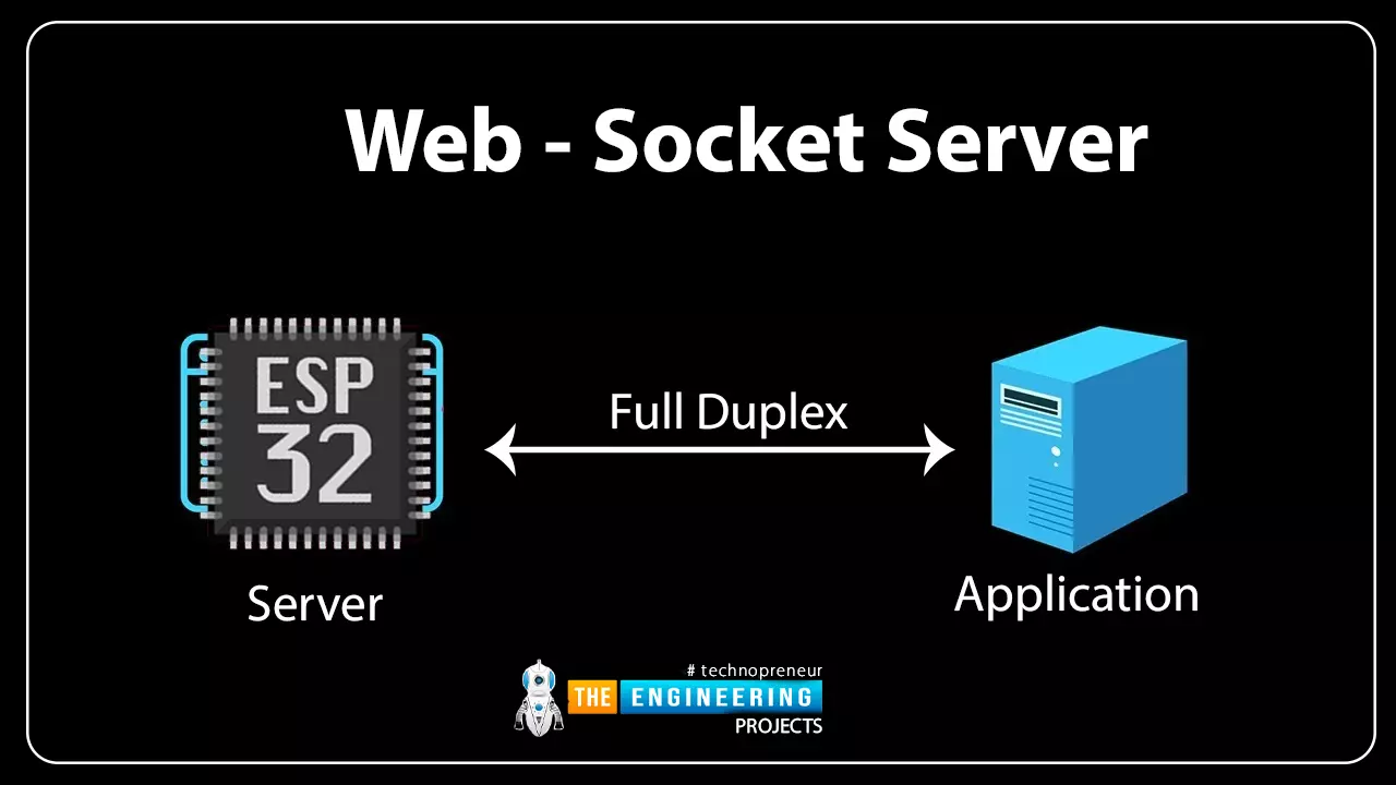
Fig 1 Web-socket server

A Web Socket is a full-duplex (both the server and the client can send and receive data at the same time) computer communication protocol. Web socket protocol, like HTTP (hypertext transfer protocol), also works in server and client communication format. A web socket uses a process known as handshaking to establish communication between the server and client. This protocol is also known as the stateful protocol. When a client device requests communication with the server, a connection is established between the server and the client, and the connection remains in place until either the server or the client terminates it.

How web socket protocol is different from HTTP protocol?

  • Both, web socket and HTTP protocols are computer communication protocols and both the protocols work on the 4th layer of TCP (transmission control protocol). But still, there are multiple specifications that make them stand apart from each other.
  • Unlike web socket protocol, HTTP is a half-duplex protocol (half-duplex protocol means that the client and server can either transmit or receive data at a time). It is a connection-oriented protocol.

Fig. 2 HTTP protocol

  • When we need to update a web page over HTTP, we have to update the complete web page before updating any data. To overcome this drawback, the most efficient solution is using a web socket protocol to receive updated data in real time. Along with that web socket protocol also saves a significant number of clock cycles for resource-intensive applications.

Fig. 3 web socket protocol

  • Whenever a client sends an HTTP request to a server, a TCP connection will be open between the server and client and when the server responds to that request the TCP connection between server and client will be terminated immediately.
  • HTTP protocol uses three-way handshaking which guarantees the transmission of the data packet and re-transmit the lost data packet.
  • Web socket starts with ws:// (web socket) or wss:// (web socket secure) whereas, HTTP starts with http://.

What is Handshaking in networking?

  • It is the process of establishing a connection between server and client. Handshaking determines the protocol, error correction scheme and speed etc. to be used for communication.

Fig. 4 Handshaking

  • Handshaking is necessary at the start of each communication session to ensure successful server and client communication despite some hardware or software configuration differences.

Three-way handshaking

In TCP/IP (transmission control protocol/ internet protocol) network, three-way handshaking is used to create a communication channel between server and client.

Three-way handshaking steps are:

  • Establishing a connection between server and client.
  • Server receives an SYN (synchronize sequence packet) packet from the client device.
  • Client device receives the ACK (acknowledgment sequence number) signal from the server and responds with an ACK packet.

Fig. 5 Three-way handshaking

Web socket Application

Web socket is used in real-time applications where a client is required to respond quickly to a change or update. The various web socket applications are:

  • Chat application
  • Online education
  • Sports update
  • Location-based applications
  • Financial Tickers

Creating Web Socket Server Using ESP32 Module

To create a web socket server using ESP32 we are using Arduino IDE as a compiler. Arduino IDE will compile the code and will also upload the compiled code into the ESP32 hardware module.

If you are not familiar with using the Arduino IDE compiler for ESP32 programming then follow our #1 tutorial that is about Introduction to ESP32 programming series.

Code

Code description

  • Download the required libraries (AsyncTCP and ESP32 WebServer) from the given link:

https://github.com/me-no-dev/AsyncTCP

https://github.com/me-no-dev/ESPAsyncWebServer

Follow our tutorial Introduction to ESP32 programming series to learn about adding a library in Arduino IDE.

  • Import the required libraries.
  • We are using three libraries to create a web socket server:
  • WiFi.h: This library is used to connect ESP32’s wifi module with the internet. It makes a wi-fi device to serve either as a client or a server.
  • AsyncTCP.h: This library is an asynchronous TCP library, used to enable a multi-connection, trouble-free network environment.
  • ESPAsyncWebServer.h: This library is used to create an asynchronous web server.

Fig. 6 Libraries

  • Initialize a variable “LED_Status” to store the status of inbuilt LED (internally connected to GPIO 2.
  • Enter the SSID and password as per your network credentials.
  • To create a web server we need to assign a port and port 80 is used for a local server.
  • Here we are creating an AsyncWebserver object with port 80 and another object AsynchWebsocket to handle connection at /ws path.
  • After assigning the port and path for the webserver and web socket respectively, the next step will be to create and design a web page.
  • We are using HTML (hypertext markup language) to create a web page to display LED status and change the state of the LED.
  • The complete HTML code is stored inside a variable “index_html”, which is used to display and style web page content.
  • Inside the index_html variable, the Style tag consists of all the instructions regarding styling the web page like the text color, font size, background color, font face etc. You can those instructions as per your requirements.

Fig. 10 <style> tag

Fig: 11 Styling the button

  • Inside the body tag, all the instructions required to display the content like text, heading etc is defined.

Fig. 12 <body> tag

  • <h1>ESP32 Web-Socket Server</h1> is the heading to be displayed on the top of the webpage.
  • <h2>LED1</h2> is the second heading for LED.
  • A button with text written to change the status of LED from LOW to HIGH and vice- versa.
  • Java-Script: When the webserver interface is fully loaded in the browser, it is used to set up a web socket connection with the server and handle data exchange via web socket. It is written inside <script> tag.

Fig. 13 script tag

  • window.addEventListener('load', onLoad) Here the onload() function calls the initWebSocket() function and initButton() function to initialize the websocket connection with the server and add event listener to the button respectively.
  • Gateway is the entry point for the web socket which gets the IP address.
  • initWebSocket() initialize the web socket connection at the obtained IP address.
  • When a connection is established between the server and client, the client will send a message to the ESP32 server to ensure the connection.
  • initWebSocket() will be called again after 2 sec if somehow the connection is closed.

Fig 14 initWebSocket()

  • The next step will be to update the status of LED on the web page.
  • When the server receives the changes in the state of LED which are requested/made by the client, the ESP32 will update the status of the LED on hardware and then acknowledge to the client.

Fig. 15 Update LED status on the web page

  • The function notifyClients() is used to update the current status of LED to the client device.

Fig. 16 Notify clients

  • handlWebSocketMessage() is a callback function that will run when the server receives a new message from the client through a web Socket.

Fig. 17 handles web (client) socket message

  • To configure the web socket server a function onEvent() is defined, to handle different asynchronous steps for the web socket.
  • The function initWebSocket() is used to initialize web socket protocol.

Fig. 18 Initialize web socket

  • The processor() is used to search for a placeholder on the web page.
  • The %STATE% placeholder will be replaced with the current LED state i.e. HIGHT for ‘1’ and LOW for ‘0’.

Fig. 19 Placeholder

Setup()

  • Inside the setup(), first of all we will initialize the serial monitor with 115200 baud rate.
  • Then, set the LED as output and write the LOW or ‘0’ state for LED.

Fig. 20

  • Call the WiFI.begin() function, which is having arguments ssid and password.
  • Continuously check the Wi-Fi status and print on the serial monitor once connected.

Fig. 21 Wifi status

  • If the ESP32 is connected with wi-fi then fetch the IP address and print it on serial monitor.
  • Iinitialize the web socket by calling initWebSocket() function.

Fig. 22

  • Pass the index_html variable as an argument to serve the text stored, when you receive a request on the URL.
  • Pass the processor() as an argument to replace the placeholder.

Fig. 23

  • Start the server.

Fig. 24

Loop()

  • The cleanupClients() function is called continuously in the loop function to close the previous client connection when the maximum client-connection limit is reached. Sometimes evening after calling the close function, the browser does not properly terminate the connection which can crash the server.
  • To avoid the server crash, cleanupClients() function is used.
  • Keep updating the status of the LED to LED_Status variable.
  • Print the LED status on the serial monitor using serial.println(“ ”).

Testing/Results

  • For testing purposes, we are using the inbuilt LED which is connected to GPIO 2.
  • You can see the updated status of the LED on the web page with an IP address of (192.168.43.233 in our project).
  • In this code, ESP32 is acting as a server both the ESP32 module and laptop/ mobile phone should be connected to the same wi-fi network.
  • Compile and upload the code into ESP32 using Arduino IDE.
  • Open the serial monitor and copy the IP address.
  • Enter the IP address in the browser.
  • A web page will be displayed on the screen.
  • Now you can change the status of ESP32’s inbuilt LED by clicking on the “change LED status” button.
  • Screenshots of the Serial monitor and web page are attached below for better understanding.
  • In the first image, you can see the IP address and status of the LED is printed on the serial monitor.

Fig 26 Arduino IDE Serial monitor

Fig. 27 Web page displaying LED status HIGH

Fig 28 Web page displaying LED status LOW

Fig. 29 ESP32 LED HIGH

This concludes the tutorial. I hope you find it helpful. In our next tutorial, we will discuss PWM (pulse width modulation) using ESP32.

ESP32 Interrupts

Hello readers, hope you all are doing great. Today, we will discuss interrupts and timers in ESP32 and how to handle internal as well as external interrupts. So, we will discuss What is interrupt, Polling, ESP32 interrupt, Software interrupts, Hardware Interrupts, IRS (Interrupt Service routine), Steps to execute an interrupt or how is an interrupt handled in the microcontroller, Code description for ESP32 interrupts with Arduino IDE, Code description for hardware interrupts, Why is it preferred to use timer to add delay instead of using delay() function. So, let's get started:
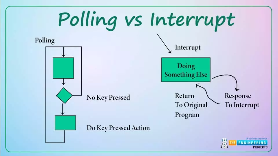
Where To Buy?
No.ComponentsDistributorLink To Buy
1ESP32AmazonBuy Now

What is Interrupt?

  • Interrupts are used when a micro-controller needs to continuously monitor for an event while the same micro-controller is executing a particular task.

Fig 1 Interrupt

  • Each interrupts has a priority level and each interrupt is executed as per their priority level.
  • You can mask or unmask a particular interrupt depending upon their properties and your requirements.

Polling

Polling is a process that performs continuous monitoring. Basically, the processor continuously monitors the state of a specific device or a peripheral, and when the status of the device satisfies the condition, the device executes the task that was required. Then it moves on to the next device to monitor until each one has been served. The processor performs no other operations and devotes all of its processing time to monitoring, and all other tasks are suspended until the current one is completed.

Fig 2 polling vs Interrupt

So, to overcome the disadvantage of the polling method, we chose the Interrupt method.

ESP32 Interrupt

ESP32 module has a dual-core processor and each core consists of 32 interrupts. Basically interrupts are of two types:

Software Interrupts:

Fig 3 ESP32 software interrupt

Software interrupts are internal which occur in response to the execution of a software instruction. For example, a timer can be used to generate a software interrupt.

Hardware Interrupts:

Fig 4 ESP32 software interrupt

Hardware interrupts are the external interrupts that are caused by an external event. For example, an external push button connected to ESP32’s GPIO or a motion sensor will generate an interrupt (event) if a motion is detected.

ISR (Interrupt Service routine)

When an interrupt occurs during normal program execution, an ISR (interrupt service routine) or an interrupt handler is called into action. The normal program execution will be halted, and the interrupt will be executed based on the priority level of the interrupt.

Fig. 5 Interrupt service routing

Every interrupt has a fixed memory location where the address of the ISR is stored.

Interrupt Vector Table refers to a memory table or memory table that is used to store the location of an interrupt service routine.

Note: IRAM_ATTR attribute should be defined for interrupt handling. As per the ESP32 datasheet interrupt service routine should run inside the RAM. Because inside the RAM it is fast to execute a code than in flash memory and when an interrupt occurs all the other tasks will be blocked or halted till the time interrupt request is served.

Steps to execute an interrupt in ESP32

When an interrupt occurs, the microcontroller will go through the following steps:

  • The microcontroller will halt the current task and will store the address of the next instruction (Program Counter or PC) on the stack (lower byte first).
  • The microcontroller will execute the higher priority interrupt first and will block the lower priority interrupts.
  • It jumps to the interrupt vector table memory location that contains the address of the interrupt service routine (ISR).
  • The microcontroller reads the interrupt vector table and jumps to the address of the ISR. It begins executing the interrupt service subroutine.
  • The microcontroller returns to the location where it was interrupted after executing the RETI instruction. First, it obtains the program counter (PC) address from the stack by inserting the stack's top bytes into the PC. The execution will then begin at that address.

Fig. 6 ESP32 Interrupt Program flow

ESP32 Interrupt Code

We are using Arduino IDE to compile the code and then upload into the ESP32 board.

If you are not familiar with the procedure of getting started with Arduino IDE and hoe to compile a code in Arduino IDE then follow our previous tutorial that is Introduction to ESP32 programming series.

// Set GPIOs for LED and Push button const int led = 2; const int button = 0;   // Timer: Auxiliary variables #define timeSeconds 10   unsigned long now = millis(); unsigned long lastTrigger = 0; boolean startTimer = false;   // Checks if button input was detected, sets LED HIGH and starts a timer void IRAM_ATTR buttonInput() { Serial.println("input is available !!!"); digitalWrite(led, HIGH); startTimer = true; lastTrigger = millis(); }   void setup() { // Serial port for debugging purposes Serial.begin(115200);   pinMode(button, INPUT_PULLUP); attachInterrupt(digitalPinToInterrupt(button), buttonInput, RISING);   // Set LED to LOW pinMode(led, OUTPUT); digitalWrite(led, LOW); }   void loop() { now = millis(); // Turn off the LED after the number of seconds defined in the timeSeconds variable if(startTimer && (now - lastTrigger > (timeSeconds*500))) { digitalWrite(led, LOW); startTimer = false; } }

Code for ESP32 Interrupts with Arduino IDE

As we have already discussed that the interrupt could be software generated (internal interrupt) or due to hardware (external interrupt). This tutorial we are using hardware or external interrupt for demonstration. You can also use software interrupts or both in a single code, as per your requirements.

Code Description for Hardware interrupt

  • For the demonstration of hardware interrupt we are using a push button which is connected to the interrupt pin and a LED for the show output.
  • First of all, let us assign two GPIOs, one is for push button (input) and another is LED. We are using the built-in LED that is GPIO_2 and a built-in push button (named as BOOT on ESP32 board) connected to GPIO_0.

Fig. 7

In this code, we are using timer to add delay instead of using delay() function.(I will also explain that why it is preferred to use timer in order to create delay instead of using delay() function after the code demonstration).

  • Next, we are defining variables which are used to set the timer for adding delay after the interrupt is being detected.
  • The variable now is defining the current time
  • The variable lastTrigger is defining the time when the interrupt is detected.
  • The variable startTimer is used to start the time when an interrupt is detected.

IRAM_ATTR

  • It is required that the interrupt service routine should have the minimum possible execution time because it halts or blocks the normal program execution.
  • The attribute IRAM_ATTR is used to run the code (interrupt code) inside the internal RAM when an interrupt occurs because RAM (random access memory) is much faster than flash memory.
  • After the execution of the interrupt code or ISR the normal code will be stored or executed inside the flash memory.

Arduino Setup() Function

  • Inside the setup() function we are initializing the serial communication with a baud rate of 115200.
  • Set the push button GPIO pin a pulled up input pin.
  • attachInterrupt() function is used to set the button pin (GPIO_0) as an interrupt pin and it will button input (interrupt) during the falling edge.
  • A function called detachInterrupt() can be used if you no longer want to use a GPIO pin as an interrupt.
  • Change the state of the LED when an interrupt is detected for

Arduino Loop() Function

Inside the loop function which is continuously running, the buttonInput function will be called every time when an interrupt occurs , which we have defined previously inside the setup() function.

  • LED will turned off after the delay of 5sec once an interrupt is detected.
  • The variable “now” will be updated every time with the current time.
  • We can check the interrupt details on serial monitor as shown in the image below:

Fig 14 Serial monitor

Why it is preferred to use Timer instead of delay()?

Delay() function is a complete software process and it is mostly used because it is easier to implement delay using only software. On the other hand, when we switch to hardware delay or use a timer to add delay the process is a bit complicated to implement.

But, when we think of a practical perspective we prefer hardware delay over software delay. Because a software delay keeps the processor busy in a continuous loop and the processor need to keep all other tasks on halt.

On the other hand, if we use a timer to add delay the processor can complete some other task while the timer is playing its own part.

This concludes the tutorial. Hope you find it helpful. In our next tutorial, we will discuss the ESP32 Web Socket server.

Syed Zain Nasir

I am Syed Zain Nasir, the founder of <a href=https://www.TheEngineeringProjects.com/>The Engineering Projects</a> (TEP). I am a programmer since 2009 before that I just search things, make small projects and now I am sharing my knowledge through this platform.I also work as a freelancer and did many projects related to programming and electrical circuitry. <a href=https://plus.google.com/+SyedZainNasir/>My Google Profile+</a>

Share
Published by
Syed Zain Nasir