Update LCD Display with ESP32 Web Server

Hello readers, I hope you all are doing great.

ESP32 is a powerful chip for Internet of Things applications. This tutorial is also based on one of the ESP32 applications in the field of IoT.

Where To Buy?
No.ComponentsDistributorLink To Buy
1ESP32AmazonBuy Now

Project Overview

In this tutorial, we will learn how to update LCD display with new data or input using a web server created with ESP32.

Fig. 1

To achieve the target, we will be using an HTML (Hypertext Markup Language) form to provide web input and then update the text displayed on LCD. The values or input received from the webserver will be further stored inside a variable in the code for further use (to display on LCD).

We have already posted a tutorial on LCD (Liquid Crystal Display) interfacing with ESP32. In that tutorial, we demonstrated how to display the hard-coded data (in the ESP32 module) on LCD.

ESP32 Web Server

A web server is computer software and hardware that accepts requests and responds to those requests using HTTP (Hypertext transfer protocol) or HTTPS (HTTP Secure) (HTTP is a network protocol for delivering online content to client user agents).

The ESP32 standalone web server is mobile-enabled and can be accessed from any device with a browser on the local network. B. Mobile phones, computers, laptops, tablets. However, all the devices must be connected to the same WiFi network to which the ESP32 is connected.

Software and Hardware requirements

  • ESP32 development board
  • 16*2 LCD display
  • 10K trim-pot
  • Breadboard or general-purpose PCB
  • Connecting Wires
  • Arduino IDE
  • h, ESPAsynchWenServer.h header files

Interfacing16*2 LCD with ESP32

There are basically two ways to connect the ESP32 to a 16 * 2 LCD display.

  1. Interface with I2C adapter
  2. Direct connection without using I2C adapter.

Connecting an LCD display without an I2C adapter is cheap, but this method requires more connection cables and is complicated to implement. On the other hand, using an I2C adapter reduces complexity but increases cost. In this tutorial, you will connect the ESP32 directly without using an I2C adapter.

Table: 1

Fig. 2: ESP32 and 16*2 LCD interfacing

For more details on interfacing 16*2 LCD with ESP32, follow our previous tutorial at www.theengineeringprojects.com

Programming ESP32

Installing ESP32 board manager in Arduino IDE:

We are using Arduino IDE to compile and upload code into ESP32 module. You must have ESP32 board manager installed on your Arduino IDE to program ESP32 module. To know more about Arduino IDE and how to use it, follow our previous tutorial i.e., on ESP32 programming series. The link is given below:

https://www.theengineeringprojects.com/2021/11/introduction-to-esp32-programming-series.html

Installing necessary libraries:

ESP32 board manager doesn’t come with inbuilt libraries to create an asynchronous web server. So we need to download the library file from external sources and then add into Arduino IDE.

We need to install two library files:

  1. ESPAsynWebServer: Follow the link https://github.com/me-no-dev/ESPAsyncWebServer to download the respective library.
  1. AsyncTCP: You can download the AsyncTCP library from the following link https://github.com/me-no-dev/AsyncTCP

Once you have successfully downloaded the required libraries, next step it to install or add these libraries in Arduino IDE.

To add the libraries in Arduino IDE, go to Sketch >> Include Library >> Add .zip library and then select the downloaded library files.

Fig. 3: adding necessary libraries

Arduino IDE code

#include < WiFi.h >

#include < AsyncTCP.h >

#include < ESPAsyncWebServer.h >

#include < LiquidCrystal.h > // LCD header file

LiquidCrystal lcd (22, 23, 5, 18, 19, 21 );

AsyncWebServer server ( 80 );

// Enter your netwrok credentials

const char* ssid = "replace this with netwrok SSID";

const char* password = "replace this with Password";

const char* PARAM_INPUT_1 = "data_field1";

const char* PARAM_INPUT_2 = "data_field2";

// HTML web page to handle data input fields

const char index_html[] PROGMEM = R"rawliteral(

<!DOCTYPE HTML> <html> <head>

<title> ESP Input Form </title>

<meta name = " viewport" content="width=device-width, initial-scale=1 ">

<style>

html{ font-family: Times New Roman; display: inline-block; text-align: justify;}

</style>

</head> <body>

<form action="/get">

Data_field1: <input type="text" name="data_field1" >

<input type="submit" value="Post ">

</form> <br>

<form action="/get">

Data_field2: <input type="text" name="data_field2">

<input type="submit" value="Post">

</form><br>

</body></html>)rawliteral";

void notFound(AsyncWebServerRequest *request) {

request->send(404, "text/plain", "Not found");

}

void setup() {


Serial.begin(115200);

WiFi.mode(WIFI_STA);

WiFi.begin(ssid, password);

if (WiFi.waitForConnectResult() != WL_CONNECTED) {

Serial.println("WiFi Failed!");

return;

}

Serial.println();

Serial.print("IP Address: ");

Serial.println(WiFi.localIP());

//===set LCD

lcd.begin(16, 2);

lcd.clear();

lcd.setCursor(1,0);

server.onNotFound(notFound);

server.begin();

// Send web page with input fields to client

server.on("/", HTTP_GET, [](AsyncWebServerRequest *request)

{

request->send_P(200, "text/html", index_html);

});

server.on("/get", HTTP_GET, [] (AsyncWebServerRequest *request) {

String inputMessage;

String inputParam;

// GET input1 value

if (request->hasParam(PARAM_INPUT_1))

{

inputMessage = request->getParam(PARAM_INPUT_1)->value();

inputParam = PARAM_INPUT_1;

}

// GET input2 value

else if (request->hasParam(PARAM_INPUT_2))

{

inputMessage = request->getParam(PARAM_INPUT_2)->value();

inputParam = PARAM_INPUT_2;

}

else

{

inputMessage = " No message sent";

inputParam = " none";

}

Serial.println ( inputMessage );

delay( 1000);

lcd.clear();

lcd.print( inputMessage);

request-> send (200, "text/html", " HTTP GET request sent to ESP32("

+ inputParam + "): " + inputMessage +

"<br><a href=\"/\"> Back to Home Page </a>");

});

}

void loop( )

{

}

Code Description

  • The first step is adding the necessary header files.
  • Here we are using two libraries:
    • The first one is WiFi.h, which is used to enable the Wi-Fi module and hence wireless network connectivity.
    • LiquidCrystal.h is used to call the necessary functions required to interface and control LCD with ESP32.
    • ESPAsynchWenServer library file is responsible for creating an asynchronous web server.
    • AsyncTCP is used to enable a multi-connection network for ESP32 (Espressif’s) microcontroller unit.

Fig. 4: Adding header files

  • Define the data and control pins (of 16*2 LCD) to be interfaced with ESP32.

Fig. 5: LCD data and control pins

  • While creating a web server we also need to assign a port and usually port 80 is used for local web server.

Fig. 6: server port

  • Enter the network credentials in place of SSID and PASSWORD.

Fig. 7: Enter Network credentials

  • The next thing is the declaration of variables for input data fields.

Fig. 8

Creating HTML Form

  • !DOCTYPE html><html> is used to describe/indicate that we are transmitting HTML, this command should always be the first thing we send.
  • <title> tag is used to write a title for the web page.
  • The next line in the code is used to make the web page responsive in any web browser.
  • The <style> tag is used to style the webpage, which includes the type of font, alignment, display etc.

Fig. 9: HTML web page

  • Next comes the HTML form for user input. We are going to create two data input fields for user input and each filed is having a Post button to send the new data string to the ESP device and the variable declared to store the input will be updated.
  • <form> tag is used to create the HTML form. Here we are creating an HTML form with two input fields namely the Data_field2 and Data_filed2 and each field is having individual Post buttons to post the input from the web server to the client.
  • The action attribute is used to specify, where to send the data input provided in the input data fields after pressing the post
  • After pressing the post button a new web page will open, indicating the status whether the input string is successfully posted or not.

Fig. 10: HTML form for data input

  • The two attributes, type and value specifies a button and the text on the button respectively.

Fig. 11: Post button.

  • If we make an invalid request, the notFound() function will be called.
 

Setup

  • Initialize the serial monitor at 115200 baud rate for debugging purpose.
    • begin() function is used to initialize the Wi-Fi module with Wi-Fi credentials used as arguments.
    • The While loop will continuously run until the ESP32 is connected to Wi-Fi network.

Fig. 12

  • If the device is connected to local Wi-Fi network then print the details on serial monitor.
  • localIP() function is used to fetch the IP address.
  • Print the IP address on serial monitor using println() function.

Fig. 13: Fetch/obtain the IP adrress

  • Initialize the 16*2 LCD using begin() function.
  • Clear the previous data from the LCD before printing or displaying the new one using clear() function.
  • Set the cursor position at row 1 and column 0 using setCursor() function.

Fig. 14: Set 16*2 LCD

  • begin() function is used to initialize the web server once ESP32 is connected with the Wi-Fi network.

Fig. 15: Initialize the server

Handling HTTP GET requests

  • The next part in the programming includes handling of HTTP GET requests.
  • When we access the route URL, we send the web page to client along with the data input fields.
  • We have defined a variable namely index_html to save the HTML text.

Fig. 16: Send web page to client

  • Next task is handling what happens when device receive a request on the /get routes.
  • To save input values, we have created two variables: inputPram and

Fig. 17

  • Next we need to check if HTTP get request contains the Data_input1 and Data_input1 These fields values are saved on PRAM_INPUT_1 and PRAM_INPUT2.
  • If the HTTP GET request contains inputs, then the inputMessage1 will be set to the value inserted in the data_field1.

Fig. read the input from HTML form

  • Else there will be no input for inputMessage.

Fig. 18

  • Print the input value saved on variable inputMessage using Serial.print command.
  • clear() command is used to clear the previous data printed on LCD.
  • New data or message received from the web server will be printed on the LCD display using print() function.

Fig. 19

  • After pressing the post button a new web page will open, indicating the status whether the input string is successfully posted or not.

Fig. 20

Testing

  • Open your Arduino IDE and paste the above code.
  • Change the network credentials, that is the SSID and PASSWORD as per you network setup.
  • Compile and upload the code into ESP32 development board.
  • Before uploading the code make sure that you have selected the correct development board and COM port.

Fig. 21: Select development board and COM port

  • Once the code is uploaded successfully, open the Serial monitor and select the 1115200 baud rate (as per your code instructions).
  • Make sure Wi-Fi to which your ESP device is supposed to connect is ON.
  • Once your ESP32 is connected to the internet, the IP address of the device will be printed on the Serial monitor.
  • Copy the IP address.
  • Open the browser and paste the IP address and press
  • A web page with HTML form containing two input fields will open as shown below:

Fig. 22: web Page

  • Enter the text in the HTML form you want to be printed on on the LCD display.
  • Press the Post

Fig. 23: Enter the Input to ESP32

  • After pressing the post button a new web page will open, indicating the status whether the input string is successfully posted or not.

Fig. 24: Input Updated

Fig. 25: IP address and Web Input on serial monitor.

Fig. 26: String input received from Web server, printed on LCD

This concludes the tutorial. We hope you found this of some help and also hope to see you soon with a new tutorial on ESP32.

Server-Sent Events with ESP32 and DHT11

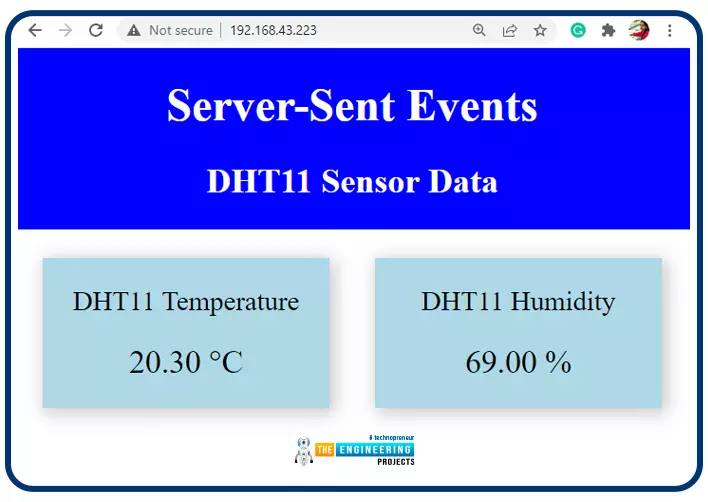
Hello readers, I hope you all are doing great. In this tutorial, we will learn how to update a webpage using Server-Sent Events and the ESP32 web server.

Where To Buy?
No.ComponentsDistributorLink To Buy
1ESP32AmazonBuy Now

What is Server-Sent Events (SSE)?

It is a server push technology that enables the client devices to receive automatic updates from a server over HTTP (Hypertext Transfer Protocol) connection. SSE also describes how the server can initiate data transmission towards the client once an initial connection with the client has been established.

We have already posted a tutorial on how to implement Web socket protocol with ESP32 which is also a protocol used to notify events to a web client. Both the Server-Sent Events (SSE) and Web-Socket technologies seem to be quite similar but they are not.

The major difference between the two is that SSE is unidirectional, where the web client can only receive the updates from the ESP32 but it can’t send updates back to ESP32. On the other hand, the Web-socket protocol is bi-directional where both the web client and ESP32 can send and receive updates/events.

Fig. 1 Server-Sent event

How does the Server-Sent Event works?

The Server-Sent Event process initiates with an HTTP request from the web client or web page to the ESP32 web server. After that, the ESP32 is ready to send updates or events to the web client as they happen. But the web client can’t send any response or data to the ESP32 server after the initial handshake takes place.

Server-sent event technology can be used to communicate an event, GPIO states or to send sensor readings to the web client, whenever a new reading is observed.

Project Overview

For demonstration purpose, we are using a DHT11 sensor with the ESP32 module. ESP32 web server will display two things i.e., temperature and humidity observed using the DHT11 sensor. So, whenever a new reading is being observed, the ESP32 sends the reading to the Web Client over Server-sent events. After receiving the latest sensor reading the client updates the web page data.

Software and Hardware requirements

  • ESP32 development board
  • DHT11 sensor
  • Connecting Wires
  • Breadboard
  • Arduino IDE
  • Necessary Libraries

DHT11 (a Temperature and Humidity sensor)

Fig. 2 DHT11 sensor

DHT11 is a humidity and temperature sensor that measures its surrounding environment. It measures the temperature and humidity in a given area. It is made up of an NTC (negative temperature co-efficient) temperature sensor and a resistive humidity sensor. It also has an 8-bit microcontroller. The microcontroller is in charge of ADC (analog to digital conversion) and provides a digital output over the single wire protocol.

The DHT11 sensor can measure humidity from 20% to 90% with +-5 percent accuracy (RH or relative humidity) and temperature from 0 degrees Celsius to 50 degrees Celsius with +-2C accuracy.

DHT11 sensors can also be used to build a wired sensor network with a cable length of up to 20 meters.

Interfacing DHT11 with ESP32 module

Table 1

Note: Connect a 10K resistor between data and power (+5V) pin of DHT11 sensor module.

Fig. 3 ESP32 and DHT11 connections/wiring

Programming with Arduino IDE

We are using Arduino IDE to compile and upload code into the ESP32 module. You must have ESP32 board manager installed on your Arduino IDE to program the ESP32 module. To know more about Arduino IDE and how to use it, follow our previous tutorial i.e., on ESP32 programming series. The link is given below:

https://www.theengineeringprojects.com/2021/11/introduction-to-esp32-programming-series.html

Steps to add the necessary libraries in Arduino IDE:

  • Go to Tools >> Manage Libraries.

Fig. 4 manage libraries

  • Search for the necessary library in Library Manager and click Install.
  • We are attaching an image, where we are installing the DHT11 sensor library.

Fig. 5 Install DHT sensor library

  • Follow the similar procedure for rest of the libraries.
  • After successfully installing all the required libraries close the Library Manager tab.

ESP32 board manager doesn’t come with inbuilt libraries to create an asynchronous web server. So we need to download the library file from external sources and then add into Arduino IDE.

We need to install two library files:

  1. ESPAsynWebServer: Follow the link https://github.com/me-no-dev/ESPAsyncWebServer to download the respective library.
  1. AsyncTCP: You can download the AsyncTCP library from the following link https://github.com/me-no-dev/AsyncTCP

Once you have successfully downloaded the required libraries, next step it to install or add these libraries in Arduino IDE.

To add the libraries in Arduino IDE, go to Sketch >> Include Library >> Add .zip library and then select the downloaded library files.

Fig. 6 adding necessary libraries

Arduino Code

#include <WiFi.h>

#include <AsyncTCP.h>

#include <ESPAsyncWebServer.h>

#include "DHT.h"

#define DHTPIN 4 // Digital pin connected to the DHT sensor

#define DHTTYPE DHT11 // DHT 11

// Initializing the DHT11 sensor.

DHT dht(DHTPIN, DHTTYPE);

// Replace with your network credentials

const char* ssid = "SSID";

const char* password = "password";

// Create AsyncWebServer object on port 80

AsyncWebServer server(80);

// Create an Event Source on /events

AsyncEventSource events("/events");

// Timer variables

unsigned long lastTime = 0;

unsigned long timerDelay = 20000; //20 sec timer delay

//==== Creating web page

const char index_html[] PROGMEM = R"rawliteral(

<!DOCTYPE HTML><html>

<head>

<title>SSE with ESP32 Web Server</title>

<meta name="viewport" content="width=device-width, initial-scale=1">

<link rel="stylesheet" href="https://use.fontawesome.com/releases/v5.7.2/css/all.css" integrity="sha384-fnmOCqbTlWIlj8LyTjo7mOUStjsKC4pOpQbqyi7RrhN7udi9RwhKkMHpvLbHG9Sr" crossorigin="anonymous">

<link rel="icon" href="data:,">

<style>

html {font-family: Times New Roman; display: inline-block; text-align: justify;}

p { font-size: 1.2rem;}

body { margin: 0;}

.topnav { overflow: hidden; background-color: blue; color: white; font-size: 1rem; }

.content { padding: 20px; }

.card { background-color: #ADD8E6; box-shadow: 2px 2px 12px 1px rgba(140,140,140,.5); }

.cards { max-width: 600px; margin: 0 auto; display: grid; grid-gap: 2rem; grid-template-columns: repeat(auto-fit, minmax(200px, 1fr)); }

.reading { font-size: 1.4rem; }

</style>

</head>

<body>

<div class="topnav">

<h1>Server-Sent Events </h1>

<h2> DHT11 Sensor Data </h2>

</div>

<div class="content">

<div class="cards">

<div class="card">

<p> DHT11 Temperature</p><p><span class="reading"><span id="temp">%TEMPERATURE%</span> &deg;C</span></p>

</div>

<div class="card">

<p> DHT11 Humidity</p><p><span class="reading"><span id="hum">%HUMIDITY%</span> &percnt;</span></p>

</div>

</div>

</div>

<script>

if (!!window.EventSource)

{

var source = new EventSource('/events');

source.addEventListener('open', function(e)

{

console.log("Events Connected");

}, false);

source.addEventListener('error', function(e)

{

if (e.target.readyState != EventSource.OPEN)

{

console.log("Events Disconnected");

}

}, false);

source.addEventListener('message', function(e)

{

console.log("message", e.data);

}, false);

source.addEventListener('temperature', function(e)

{

console.log("temperature", e.data);

document.getElementById("temp").innerHTML = e.data;

}, false);

source.addEventListener('humidity', function(e)

{

console.log("humidity", e.data);

document.getElementById("hum").innerHTML = e.data;

}, false);

}

</script>

</body>

</html>)rawliteral";


void setup() {

Serial.begin(115200); //initialize serial monitor

//===set and initialize Wi-Fi

WiFi.mode(WIFI_STA);

WiFi.begin(ssid, password);

Serial.print("Connecting to WiFi ..");

while (WiFi.status() != WL_CONNECTED)

{

Serial.print('.');

delay(1000);

}

Serial.print("IP Address: ");

Serial.println(WiFi.localIP()); // print the IP address

//====Initialize DHT11 sensor

dht.begin();

//====Handle Web Server

server.on("/", HTTP_GET, [](AsyncWebServerRequest *request){

request->send_P(200, "text/html", index_html);

});

// Handle Web Server Events

events.onConnect([](AsyncEventSourceClient *client)

{

if(client->lastId())

{

Serial.printf("Client reconnected! Last message ID that it got is: %u\n",

client->lastId());

}

// send event with message "hello!", id current millis

// and set reconnect delay to 1 second

client->send("hello!", NULL, millis(), 10000);

});

server.addHandler(&events);

server.begin();

}

void loop()

{

delay(2000);

float humidity = dht.readHumidity();

// Read temperature as Celsius (the default)

float temperature = dht.readTemperature();

// Check if any reads failed and exit early (to try again).

if (isnan(humidity) || isnan(temperature))

{

Serial.println(F("Failed to read from DHT sensor!"));

return;

}

if ((millis() - lastTime) > timerDelay)

{

// Send Events to the Web Server with the Sensor Readings

events.send("ping",NULL,millis());

events.send(String(temperature).c_str(),"temperature",millis());

events.send(String(humidity).c_str(),"humidity",millis());

Serial.print(F("Humidity(%): "));

Serial.println(humidity);

Serial.print(F("Temp.: "));

Serial.print(temperature);

Serial.println(F("°C "));

}

}

Code Description

  • Here we are using four libraries:
    • The first one is WiFi.h, which is used to enable the Wi-Fi module and hence wireless network connectivity.
    • DHT.h is used to call the necessary functions required to interface DHT sensor with ESP32.
    • ESPAsynchWenServer library file is responsible for creating an asynchronous web server.
    • AsyncTCP is used to enable multi-connection network for ESP32 (Espressif’s) microcontroller unit.

Fig. 7 Header files

  • Next step is the declaration of variables for DHT11 sensor.
  • We are declaring 2 variables, the first one is the DHTPIN to store the GPIO number receiving input from DHT11 sensor and another variables is to define the type of DHT (i.e., whether DHT11 or DHT22).

Fig. 8 Global declarations

  • Next we are creating a DHT object called dht in the DHT sensor type (defined earlier) and the DHT pin.

Fig. 9

  • Enter the network credentials in place of SSID and PASSWORD.

Fig. 10 Enter Network credentials

  • While creating a web server we also need to assign a port and usually port 80 is used for local web server.

Fig. 11 Server port

  • Next step is creating a new event source(on /events).

Fig. 12 Event source

  • Timer variable declaration: the timerDelay and lastTime variables are declared to add delay using timer, instead of using delay() function. Here we are adding a delay of 20 seconds which means the web browser will be updated with new sensor reading in every 20 sec.

Fig. 13 Timer Variables

Creating the Web Page

  • !DOCTYPE html><html> is used to describe/indicate that we are transmitting HTML, this command should always be the first thing we send.
  • <title> tag is used to write title for the web page.

Fig. 14

  • The <style> tag is used to style the webpage, which includes the type of font, alignment, display, color, dimensions etc. You can make changes in the <style> tag as per your requirements.

Fig. 15

  • The content, which is to be displayed on the Web page is written inside the <body> tag. The <body> tag includes two headings h1 and h2 and sensor readings (temperature and humidity).

Fig. 16

Initializing an Event-Source connection

  • JavaScript is written inside the inside the <script> tag, which is responsible for initializing an event source connection with the web server and also to handle the events received from the web server.
  • An object EventSource is created and along with that the URL of the webpage sending the updates is also specified.
  • addEventListener() function is used to listen to the messages coming from the web server, once the event source is initiated successfully.

Fig. 17

  • Next task is adding an event listener for Whenever a new temperature reading is observed from the DHT11 sensor, ESP32 sends a “temperature” event to the web client.

Fig. 18

  • Similarly, another event is generated for It prints the latest readings on the web browser & puts the received data into the element with respective ID on the webpage.

Fig. 19

Setup

  • Initialize the serial monitor at a 115200 baud rate for debugging purposes.
    • begin() function is used to initialize the Wi-Fi module with Wi-Fi credentials used as arguments.
    • The While loop will continuously run until the ESP32 is connected to the Wi-Fi network.

Fig. 20

  • If the device is connected to a local Wi-Fi network then print the details on the serial monitor.
  • localIP() function is used to fetch the IP address.
  • Print the IP address on the serial monitor using println() function.

Fig. 21 Fetch/obtain the IP address


Fig. 22 Initialize DHT sensor

Handling HTTP GET requests

  • The next part in the programming includes handling HTTP GET requests.
  • When we access the route URL, we send the web page to the client along with the data input fields.
  • We have defined a variable namely index_html to save the HTML text.

Fig. 23

Handling Server Event source

  • The next task is setting up the event source on the webserver.

Fig. 24 Handling server events


Initializing web server

  • Initialize the webserver using begin() function.

Fig. 24 initializing web server


Loop()

  • DHT11 is a very slow sensor. It takes almost 250ms to read temperature and humidity.
  • So it is preferred to wait a few seconds before a new measurement or updated sensor reading.
  • Next, we are defining a float type variable ‘h’ to store humidity measured from the DHT11 sensor.
  • readHumidity() function is used to observe the humidity value.
  • readTemperature() function is used to read the surrounding temperature with the DHT11 sensor.

Fig. 25

 
  • If somehow the sensor fails to read or observer temperature and humidity values, then the respective results will be printed on the serial monitor.

Fig. 26 If error occurs while reading data from DHT11

Sending Events to the server

  • Send the updated events or the latest observation from the DHT11 sensor the web browser over the local network.
  • The sensor readings will be updated in every 20 second as per the code instructions.

Fig. 27 Sending events to the server

  • Print the temperature and humidity readings (observer form the DHT11 sensor) on the Serial monitor.

Fig. 28 Print Sensor data on the Serial monitor

Testing

  • Open your Arduino IDE and paste the above code.
  • Change the network credentials, that is the SSID and PASSWORD as per you network setup.
  • Compile and upload the code into ESP32 development board.
  • Before uploading the code make sure that you have selected the correct development board and COM port.

Fig. 29 Select development board and COM port

  • Once the code is uploaded successfully, open the Serial monitor and select the 1115200 baud rate (as per your code instructions).
  • Make sure Wi-Fi to which your ESP device is supposed to connect is ON.
  • Once your ESP32 is connected to the internet, the IP address of the device will be printed on the Serial monitor.
  • Copy the IP address.
  • Open the browser and paste the IP address and press
  • A web page will appear, as shown below:

Fig. 30

  • The web page will be updated with new data every 20 seconds, as per the code instructions and we do not even need to refresh the web page for latest event updates due to SSE technology.

Fig. 31

This concludes the tutorial. I hope you found this of some help and also hope to see you soon with a new tutorial on ESP32.

Syed Zain Nasir

I am Syed Zain Nasir, the founder of <a href=https://www.TheEngineeringProjects.com/>The Engineering Projects</a> (TEP). I am a programmer since 2009 before that I just search things, make small projects and now I am sharing my knowledge through this platform.I also work as a freelancer and did many projects related to programming and electrical circuitry. <a href=https://plus.google.com/+SyedZainNasir/>My Google Profile+</a>

Share
Published by
Syed Zain Nasir