ESP8266 – Serial Communication

Today we will talk about an extremely powerful tool in the use of microcontrollers. The Serial communication, specifically the USART (Universal Synchronous Asynchronous Receiver Transmitter) standard. The system works using two wires. RX (Receiver) and TX (Transmitter), connecting two devices. The RX of one is connected to the TX of the other. If the choice is for a synchronous connection, it may be necessary to add one or two more pins to operate as a “traffic light”. But most current microcontrollers can operate asynchronously, which saves us the expense of pins. Data is sent, as the name implies, in a series of bits. 
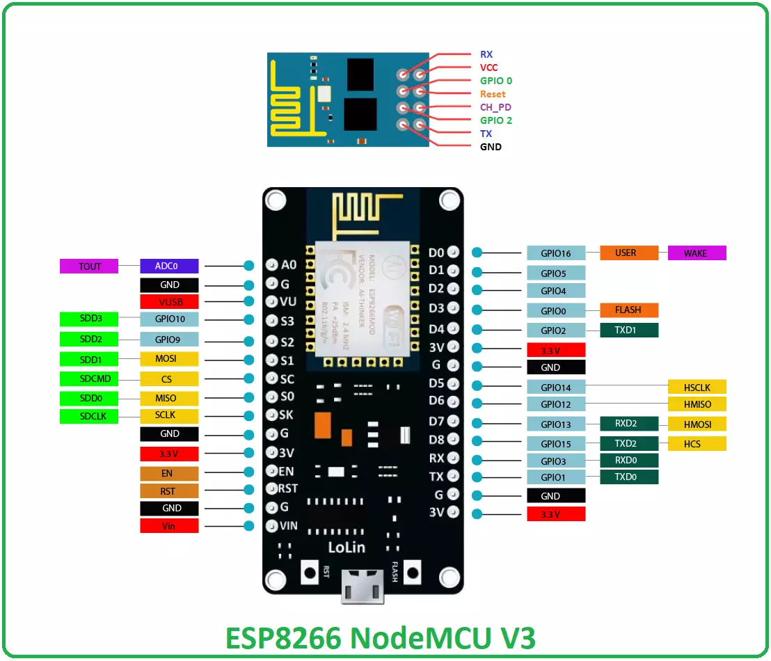
ESP8266 provides us with two ports, one of them converted to USB in the NodeMCU module.
Where To Buy?
No.ComponentsDistributorLink To Buy
1ESP8266AmazonBuy Now

Applications

The range of uses of serial communication is limited only by creativity. Here I will mention three more general scenarios and detail some applications within them.

1. Communicating with computers

With a USB cable, we were able to connect the NodeMCU with a computer via Serial. Arduino IDE already gives us the first use. With Serial Monitor, we can send commands or debug the functioning of our code. But the integration with other software is pretty powerful. Imagine, for example, access control in which a circuit with ESP8266 reads an RFID card and sends it via Serial to a Permission Validation System. Or even an LED panel that receives a software display text.

2. Communicating with microcontrollers

Probably the most common application. Whether to integrate into a preexisting circuit or to distribute functionality between microcontrollers. This integration can be done between different microcontrollers. As long as they operate with the same voltage (3.3V) or use a level converter. An application example is to integrate the ESP8266 wifi with the analog ports of an ATMEGA328 to build an IoT toxic gas sensor. We already know that the ESP8266's analog port is quite inefficient. Then it is possible to perform the analog reading on the ATMEGA328 and send the information to ESP8266 by Serial.

3. Communicating with industrial machines

This, without a doubt, is the most interesting way to integrate industrial machinery with WEB systems. The older industrial equipment that allows some automation, provides RS232 or RS485 ports for integration with PLCs. In these cases, the commands are pretty plastered, but hopefully, well documented. The voltage level is 12V or 24V, but there are converters and logic levels to solve this. The industry 4.0 paradigm has been operating to make this kind of integration. Some PLCs are already developed with wifi modules. And on that account, circuits with the ESP8266 have the immense advantage of low cost. The vision behind this is to be able to remotely monitor or control an entire industrial plant. Tracking KPIs for predictive maintenance, doing recalibrations, and managing production.

Main Functions

The Serial library has a good variety of functions for Serial communication, but most are for very specific uses. We will discuss the most common ones and may return to others in the future as needed by the projects.

Serial.begin()

The first function to be used. It initializes Serial communication informing the data transfer speed (in bits per second) and, optionally, a configuration parameter. By default, Serial is configured to send data in 8-bit packets plus a terminator, not including parity. The best way to imagine this communication is to imagine a train, where each byte (8 bits) sent is a car, and the terminator is the connection between them. This standard is used in most devices, but if you need to integrate a device with another standard, the config parameter allows you to change the number of bits in the packet (from 5 to 8), the number of stop bits (1 or 2 ) and enable or disable parity (a packet integrity check). The speed uses some preset values. The fastest that remains stable for the ESP8266 is 115200 changes per second. So we could start with: Serial.begin(155200) The function below presents the same result, making the config parameter explicit. Serial.begin(115200, SERIAL_8N1)

Serial.available()

The function returns an integer with the number of bytes available in the read buffer. The maximum of bytes in the buffer is 64. This function is very useful for monitoring incoming information. Value = Serial.available()

Serial.read()

The function returns the most recent byte in the input buffer and removes it from the buffer. It is ideal if your communication is byte-to-byte. For example, if you are receiving input from a keyboard, the function would return the key you typed. It returns an integer with byte or -1 if no data is available.

Serail.readString()

This function is best suited for reading strings. Like words. It is the equivalent of calling the read() function continuously until it reads all the information from the buffer. The function returns a string with the data.

Serial.print() and Serial.println()

The two functions are very similar. It takes a value and sends it serially in ASCII format. It is also possible to define the numerical base before sending (binary, decimal...) and the number of decimal places. The function can be used either in the format: Serial.print(value) And the format: Serial.print(value, format) The table below presents some usage examples. The println function works pretty much the same, but it adds the return character ‘\r’ and newline ‘n’ at the end of the packet. It's the equivalent of typing in a text editor and pressing the "Enter" key.

Serial Monitor

The Arduino IDE provides a very powerful tool for debugging and testing Serial communication. The Serial Monitor. The tool is pretty intuitive, but let's take a look at its fields.
  • Sending data: This allows us to send commands directly to the microcontroller
  • Autoscroll: Very useful when we've already received enough information to fill the screen
and don't want to move it down manually.
  • Terminator: Choose whether or not to include the new line and carry return characters at the end of the message before
  • BaudRate: Defines the communication It must be the same as the microcontroller, or
packet loss or character misreading problems will occur.

Controlling and monitoring an LED

Let's make a simple code to control and monitor the NodeMCU LED from the Serial monitor. The code will monitor the Serial, and each time it receives the command “ON”, it will turn on the LED, when it receives “OFF”, it will turn off the LED when it receives “STATUS”, it will return the status of the LED in the Serial. We will create three functions to perform the actions.
  • turnOn() : To turn on the
  • turnOff() : To turn off the
  • statusLED() : To read the pin status and return information in the serial.
We initialize the Serial in the Setup function. In the loop() function, we check if there is any data in the input buffer of the serial, if there is, it saves the buffer values in the variable “payload”. Finally, we check the payload value to decide the action. Here it is important to note that we use an equality comparison and that “ON” is different from “ON “. For this reason, when sending the information through the Serial Monitor, we choose the “No line ending” option. And so is our final code. Compiled, written to nodeMCU. Open the Serial Monitor, remember to put the correct baud rate and the "No Line ending" and send one of our 3 commands. This is simple code, but very powerful. So, that was all for today. I hope you have enjoyed today's tutorial. If you have any questions, please ask in the comments. Thanks for reading.

ESP8266 Pinout, Datasheet, Features & Applications

Hello friends! Hope you are doing well. Today, we will have a look at the detailed Introduction to ESP8266 WiFi module. ESP8266 is a very low-cost & user-friendly WiFi module, which develops a simple TCP/IP connection and can easily be interfaced with microcontrollers via Serial Port. The first chip in this series was ESP-01 which gained sheer attention in the market. In this tutorial, we will discuss the ESP8266 WiFi module along with its pinout, features, specifications, applications and datasheet. Let's dive in and nail down everything related to this device.

ESP8266 WiFi Module

  • ESP8266 (also called ESP8266 Wireless Transceiver) is a cost-effective, easy-to-operate, compact-sized & low-powered WiFi module, designed by Espressif Systems, that supports both TCP/IP and Serial Protocol.
  • It's normally used in IOT cloud-based embedded projects and is considered the most widely used WiFi module because of its low cost and small size.
  • It runs at an operating voltage of 3V and can handle a maximum voltage of around 3.6 V, so an external logic level converter is required if you are using 5V supply.
  • ESP8266 WiFi module can easily be interfaced with microcontrollers board (i.e. Arduino UNO) via Serial Port.
  • There are numerous breakout boards available based on ESP8266 WiFi Module (i.e. ESP8266 NodeMCU V3).
  • Beause of its compact size, its mostly used in autonomous projects (i.e. Robotics).
  • Other than ESP8266, "Espressif Systems" has designed many other ESP WiFi modules, few of them are shown in below figure:
Now let's have a look at the ESP8266 Pinout, necessary for interfacing with microcontrollers.

ESP8266 Pinout

  • ESP8266 Pinout consists of 8 pins in total, which are given in below table along with their operation:
ESP8266 Pinout
No. Pin Name Working
1 RX Serial Receiver Pin
2 Vcc Power Pin (+3.3 V; can handle up to 3.6 V)
3 GPIO 0 General-purpose I/O No. 0
4 RST Reset
5 CH_PD Chip power-down
6 GPIO 2 General-purpose I/O No. 2
7 TX Serial Transmitter Pin
8 GND Ground
  • Each pin comes with a specific function associated with it where Vcc and GND are voltage source and ground respectively.
  • RX and TX are used for communication where TX is dedicated for data transmission and RX is used receiving data.

ESP8266 Datasheet

  • You can download ESP8266 Datasheet by clicking the below button:
Download ESP8266 Datasheet

ESP8266 Features

  • It is also known as a system-on-chip (SoC) and comes with a 32-bit Tensilica microcontroller, antenna switches, RF balun, power amplifier, standard digital peripheral interfaces, low noise receive amplifier, power management module and filter capability.
  • The processor is based on Tensilica Xtensa Diamond Standard 106Micro and runs at 80 MHz.
  • It incorporates 64 KiB boot ROM, 80 KiB user data RAM and 32 KiB instruction RAM.
  • It supports Wi-Fi 802.11 b/g/n around 2.4 GHz and other features including 16 GPIO, Inter-Integrated Circuit (I²C), Serial Peripheral Interface (SPI), 10-bit ADC, and I²S interfaces with DMA.
  • External QSPI flash memory is accessed through SPI and supports up to 16 MiB and 512 KiB to 4 MiB is initially included in the module.
  • It is a major development in terms of wireless communication with little circuitry. and contains onboard regulator that helps in providing 3.3V consistent power to the board.
  • It supports APSD which makes it an ideal choice for VoIP applications and Bluetooth interfaces.

How to Power Up the Module

  • You can power up the device with PC port using USB to Serial adaptor. The 2 AA  and LIPO batteries are equally handy for powering up the device.
  • It is advised to not power this device directly with 5V dev board. Doing so can severely affect the quality and overall performance of the device.

ESP8266 NodeMCU

  • There are numerous breakout boards designed by different companies, based on this ESP8266 WiFi module.
  • Among these breakout boards, ESP8266 NodeMCU is the most popular one.
  • Here's the Pinout Diagram of ESP8266 NodeMCU:

ESP8266 Projects & Applications

ESP8266 WiFi module is widely used in embedded projects and thus brings WiFi capability. Here's few ESP8266 Projects & Applications:
  • Wireless Web Server
  • Geolocation using ESP8266
  • Pressure Sensors on Railway Tracks
  • Air Pollution Meter
  • Temperature logging system
  • World’s smallest IoT project
  • Wi-Fi controlled robot
  • Humidity and temperature monitoring
  • M2M using ESP8266
That's all for today. I hope I have given you everything you needed to know regarding this WiFi module. If you are unsure or have any question, you can ask me in the comment section below. I'd love to help you in any way I can. You are most welcome to keep us updated with your suggestions so we keep providing quality work that resonates with your needs and demands. Thanks for reading the article.
Syed Zain Nasir

I am Syed Zain Nasir, the founder of <a href=https://www.TheEngineeringProjects.com/>The Engineering Projects</a> (TEP). I am a programmer since 2009 before that I just search things, make small projects and now I am sharing my knowledge through this platform.I also work as a freelancer and did many projects related to programming and electrical circuitry. <a href=https://plus.google.com/+SyedZainNasir/>My Google Profile+</a>

Share
Published by
Syed Zain Nasir