Hello friends, I hope you are doing well. In the previous tutorial, we studied the working principle of a relay. Today, we will connect a 12 V relay to a PIC18F4550 microcontroller through a ULN2003A driver.
A relay coil needs more voltage and current than a microcontroller pin should provide. It is also an inductive load, so it produces a voltage transient when switched off. The ULN2003A solves these interface problems by providing seven low-side Darlington drivers and seven internal clamp diodes in one package.
The key point is that the ULN2003A does not convert a 5 V logic signal into a 12 V output. The 12 V energy comes from a separate 12 V supply. A logic high merely turns on one internal driver, which connects the low side of the relay coil to ground. We will examine that current path, calculate the important values, build the circuit and write a small test program.
Why a Relay Needs a Driver
Suppose the relay has a 12 V coil rated at 400 mW. Its approximate current is:
Icoil = Pcoil / Vcoil = 0.400 W / 12 V = 0.0333 A = 33.3 mA
The approximate coil resistance is:
Rcoil = Vcoil / Icoil = 12 V / 0.0333 A = 360 ohms
A PIC18F4550 output operates from its logic supply and is not a 12 V power output. Microchip's PIC18F2455/2550/4455/4550 datasheet lists 25 mA per pin under absolute maximum ratings, but an absolute maximum is a damage boundary rather than a recommended operating point. Output-voltage specifications, total port current and device power dissipation impose additional restrictions. A 33.3 mA, 12 V coil therefore must not be connected directly to a PIC pin.
The driver must perform three jobs:
- Accept the microcontroller's low-current logic signal.
- Switch the coil current from the separate 12 V supply.
- Provide a controlled path for inductive current when the coil is turned off.
What Is the ULN2003A?
The ULN2003A is a seven-channel NPN Darlington transistor array. Each channel has an input, an open-collector output and access to a common emitter connection. The package also contains common-cathode clamp diodes intended for inductive loads such as relays, solenoids and small unipolar stepper motors.
According to the current Texas Instruments ULN2003A datasheet, the device provides 50 V outputs, a 500 mA rating for a single collector channel and a 2.7 kΩ series base resistor on each ULN2003A input. These headline limits do not mean seven channels may each carry 500 mA simultaneously. Package power dissipation, ambient temperature, duty cycle and the number of active channels reduce the allowable combined load. Use the datasheet graphs and thermal information for a final design.
| Feature | Practical meaning |
|---|---|
| Seven channels | One package can control as many as seven suitable loads independently |
| Darlington input stage | Provides high current gain but has a larger on-state voltage than a single transistor or MOSFET |
| Open-collector output | The output sinks current to ground; it does not source the relay supply voltage |
| Internal input resistor | A 5 V logic output can normally connect directly to a ULN2003A input |
| Clamp diode per output | Provides an inductive-current path when COM is connected correctly |
| Common emitter | Pin 8 connects the seven driver emitters to ground |
ULN2003A Pin Configuration
In the 16-pin DIP package, the inputs and corresponding outputs are placed on opposite sides:
| Pin | Name | Function |
|---|---|---|
| 1 to 7 | 1B to 7B | Logic inputs for channels 1 to 7 |
| 8 | E | Common emitter and driver ground |
| 9 | COM | Common cathode connection for the internal clamp diodes |
| 10 to 16 | 7C to 1C | Open-collector outputs for channels 7 to 1 |
Channel 1 uses input pin 1 and output pin 16. Channel 2 uses pins 2 and 15, and the pattern continues toward the center of the package. Pin 8 must connect to the controller and driver ground. When driving relay coils from +12 V, pin 9 normally connects to +12 V so the internal clamp diode for each active channel has a return path.
How One ULN2003A Channel Controls the Relay
The high side of the coil connects directly to +12 V. Its low side connects to a ULN2003A collector output. When the PIC output is low, the Darlington pair is off and almost no coil current flows. When the PIC output is high, the Darlington pair turns on and sinks current through this path:
+12 V supply, relay coil, ULN2003A output transistor, ground
The output is therefore logically inverting at the collector. A high input produces a low collector voltage and energizes the coil. A low input releases the relay.
The Darlington output does not behave like an ideal zero-ohm switch. It has an on-state collector-emitter voltage. If that voltage is 1.0 V at the chosen current, the coil receives approximately:
Vcoil = 12 V - 1.0 V = 11.0 V
Check that the relay will operate at the lowest supply voltage after subtracting the driver's worst-case on-state voltage and wiring losses. A supply marked 12 V may also have tolerance, ripple and cable drop.
Why the COM Pin Matters
A relay coil stores magnetic energy while current flows. The stored energy is approximately:
E = 1/2 × L × I²
When the transistor turns off, the inductor tries to keep the current flowing. Without a clamp, the output voltage can rise until a transistor avalanches or another path breaks down. Inside the ULN2003A, each output has a diode whose cathode joins the COM pin. Connecting COM to the positive coil supply lets the decaying current circulate through the coil and diode.
Do not confuse COM with the common terminal of the relay contacts. ULN2003A COM is only the common cathode node for its suppression diodes. The relay's contact COM belongs to the electrically separate load circuit.
Complete Relay Interface Circuit
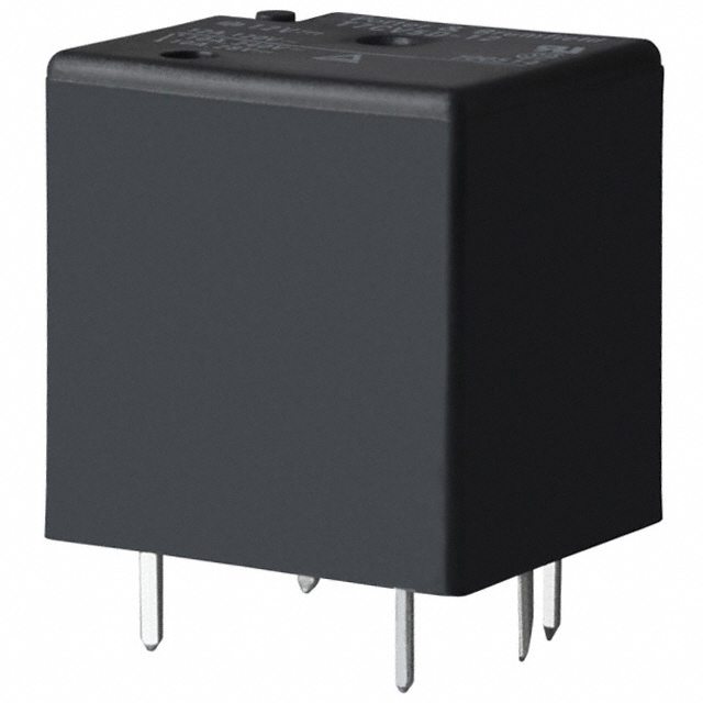
The original project uses a PIC microcontroller, ULN2003A, 12 V relay and indicator LED. The correct functional connections for one channel are:
- Connect the PIC18F4550 output pin to ULN2003A input 1, pin 1.
- Connect ULN2003A pin 8 to circuit ground.
- Connect the low side of the relay coil to ULN2003A output 1, pin 16.
- Connect the high side of the relay coil to the regulated 12 V supply.
- Connect ULN2003A COM, pin 9, to the same +12 V coil supply.
- Join the PIC ground and 12 V supply negative at the driver ground when both supplies are non-isolated parts of this circuit.
- Wire the load through the relay COM and either NO or NC contact, according to the required default state.
The PIC does not need a pull-up resistor merely to drive a ULN2003A input. The ULN2003A already includes its input resistor, and a normal push-pull PIC output actively drives both high and low. A pull-down may be added only when the system needs a defined off state while the microcontroller pin is high-impedance during reset. Its value must be chosen so it does not prevent a valid input high.
Circuit Diagram of Relay with ULN2003A
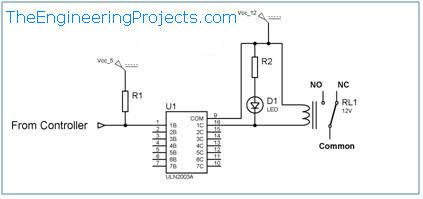
In the circuit diagram, trace the coil path separately from the contact path. The relay coil belongs to the 12 V driver circuit. The contact COM, NO and NC terminals form an independent switch for the external load. Keeping these two paths conceptually separate prevents one of the most common relay wiring mistakes.
Indicator LED Calculation
If an LED is connected to indicate the active 12 V output, it needs a series resistor. For a red LED with a 2.0 V forward drop and a desired current of 5 mA:
R = (12 V - 2.0 V - 1.0 V) / 0.005 A = 1800 ohms
The 1.0 V term represents an illustrative ULN2003A on-state voltage. A standard 1.8 kΩ or 2.2 kΩ resistor is suitable for this indication example, subject to the actual LED and driver values. With 1.8 kΩ, resistor power is approximately:
P = I²R = 0.005² × 1800 = 0.045 W
A 0.25 W resistor has comfortable margin. Do not place an LED without a series resistor across the supply.
Example PIC18F4550 Program
The following mikroC PRO for PIC example drives ULN2003A channel 1 from RB0. It energizes the relay for one second and releases it for one second. Adjust the oscillator setting in the project to match the actual hardware.
void main() {
    ADCON1 = 0x0F;       // Configure analog-capable pins as digital
    TRISB.B0 = 0;        // RB0 is an output
    LATB.B0 = 0;         // Start with the relay released

    while (1) {
        LATB.B0 = 1;     // ULN2003A channel ON, relay energized
        Delay_ms(1000);

        LATB.B0 = 0;     // ULN2003A channel OFF, relay released
        Delay_ms(1000);
    }
}
Using the output latch avoids read-modify-write surprises that can occur when code changes individual port bits. The relay starts released because the latch is cleared before the loop. For a real controller, set a safe initial state as early as possible and consider what the load must do during reset, programming and power failure.
Logic and Relay State Table
| PIC output | ULN2003A channel | Coil | COM connection |
|---|---|---|---|
| Low | Off | De-energized | COM to NC |
| High | On and sinking current | Energized | COM to NO |
This table assumes a standard, non-latching SPDT relay. A latching relay needs a different drive sequence, and some modules add an inverting input stage that changes the software logic.
Power and Thermal Checks
Each active Darlington channel dissipates power approximately equal to:
Pchannel = VCE(on) × Icoil
With an illustrative 1.0 V on-state voltage and a 33.3 mA coil:
Pchannel = 1.0 V × 0.0333 A = 0.0333 W
One small relay is easy for the package thermally, but seven larger loads can produce substantial heat. Calculate every active channel using the datasheet's worst-case voltage at the relevant current, sum the losses and check the package thermal limits at the highest ambient temperature. The 500 mA single-channel rating cannot be multiplied by seven without this analysis.
The 12 V source must provide the sum of all coil currents and indicator currents, with startup and tolerance margin. Four 33.3 mA coils require about 133 mA before LEDs and other loads. A 12 V, 250 mA regulated supply would provide useful margin for that illustrative case, but the actual relay datasheet controls the calculation.
Using Several ULN2003A Channels
The remaining six channels work in the same way. Connect each PIC output to a separate input and each relay coil low side to its matching collector output. All channels share pin 8 for ground and pin 9 for the internal clamp-diode cathodes.
Do not parallel outputs casually. The manufacturer permits paralleling for increased capability, but current sharing, input connections, transient behavior and total power still need analysis. For a single load near the limit, a suitable logic-level MOSFET or dedicated driver may give lower voltage drop and better thermal performance.
Using 3.3 V Microcontrollers
The ULN2003A was designed around TTL and 5 V CMOS drive and contains 2.7 kΩ input resistors. A 3.3 V output may operate it for some load currents, but you must compare the microcontroller's guaranteed output-high voltage with the ULN2003A input requirements at the required collector current and over temperature. Do not treat the word compatible as a guarantee for every 3.3 V controller and every load.
For a new 3.3 V design, a low-side MOSFET array or a driver specifically characterized for 3.3 V logic may provide lower loss and clearer margins. The original PIC18F4550 project uses 5 V logic, which matches the traditional ULN2003A use case.
Relay Contact Wiring
Choose NO when the load should remain off with the coil de-energized. Connect the supply side of the load circuit to relay COM and the switched conductor to NO. Choose NC when the load must remain on while the coil is off and turn off when the relay energizes.
Contact selection must consider voltage, continuous current, inrush current, load type and electrical life. A relay rated for a stated resistive load may need substantial derating for motors, solenoids, lamps or capacitive power supplies. The ULN2003A protects its own outputs from the coil; it does not suppress arcing or transients in the separate contact load.
For a DC inductive load switched by the contacts, a diode may be suitable across that load. AC loads require a different suppression method, often an RC snubber or voltage-dependent device selected for the circuit. Suppression design affects release time, contact stress and safety, so follow the load and relay manufacturers' guidance.
Safe Testing Procedure
- Leave the contact load disconnected and verify all IC, relay and supply pin numbers against their datasheets.
- With power off, check that ULN2003A pin 8 goes to ground and pin 9 goes to the positive coil supply.
- Power the PIC and 12 V coil circuit through current-limited bench supplies if available.
- Run the test program and measure the ULN2003A input, collector output and voltage across the coil.
- Listen for the relay and use continuity mode, with power removed, to identify the contact state.
- Test first with a safe low-voltage load.
- Connect the final load only after verifying ratings, protection, wiring clearances and enclosure requirements.
Troubleshooting
| Problem | Likely cause | Check |
|---|---|---|
| Relay never energizes | No 12 V coil supply, wrong pinout or missing ground reference | Measure the supply, input and output while commanding ON |
| Input changes but output stays high | ULN input is not recognized or emitter ground is open | Verify logic-high voltage and pin 8 connection |
| Relay chatters | Coil voltage falls below the hold level or supply is unstable | Measure coil voltage during operation and improve supply decoupling |
| ULN2003A becomes hot | Too much channel current or excessive total package dissipation | Calculate every channel and compare with thermal limits |
| Controller resets at switch-off | Clamp path, grounding or supply decoupling is incorrect | Verify COM wiring, short current loops and local bypass capacitors |
| Relay clicks but load stays off | Load is on the wrong contact or contact circuit is incomplete | Identify COM, NO and NC from the relay datasheet |
| Relay releases slowly | Normal effect of diode clamping | Use a properly rated faster clamp only when the timing requires it |
Safety When Switching Mains Loads
A relay does not make a breadboard safe for mains voltage. Solderless breadboards, loose jumpers and typical hobby clearances are unsuitable for hazardous voltage. The relay, PCB creepage and clearance, fuse, connectors, wire, enclosure and earthing must all satisfy the applicable electrical standards. Use a certified enclosed module or qualified hardware design if the load is connected to mains power.
Keep the low-voltage PIC and ULN2003A area physically separated from contact wiring. Disconnect all power before changing the circuit. The coil side can be tested completely with a low-voltage load before any hazardous circuit is considered.
Practical Review
The PIC18F4550 supplies only a logic command. A high level at a ULN2003A input turns on the corresponding Darlington pair, which sinks current through the 12 V relay coil. Pin 8 completes the ground path, while pin 9 connects the internal clamp diodes to the positive coil supply. The relay contacts then switch an electrically separate load within their own ratings.
This interface is convenient when several modest DC coils must be controlled. Its main tradeoff is the Darlington on-state voltage and resulting heat. A modern MOSFET driver may be better for low-voltage coils, high current or tight efficiency targets, but the ULN2003A remains easy to understand and useful when its electrical and thermal limits are respected.
Frequently Asked Questions
Does the ULN2003A increase 5 V to 12 V?
No. The 12 V supply powers the relay coil. The ULN2003A acts as a controlled low-side switch that completes or interrupts the coil's path to ground.
Where should ULN2003A pin 9 connect?
For 12 V relay coils using the internal clamp diodes, connect COM pin 9 to the positive 12 V coil supply. It is not a power input for the IC's logic and it is not the relay contact COM terminal.
Do I need an external flyback diode?
The ULN2003A contains one clamp diode per channel. It is effective only when COM is connected correctly. An external diode may be redundant in the standard arrangement, although specific timing, wiring or protection requirements can justify a different clamp network.
Can one ULN2003A drive seven relays?
It can control seven channels, but the answer depends on each coil current, how many are on together, ambient temperature and package dissipation. Perform the combined thermal calculation instead of multiplying the single-channel headline rating by seven.
Why does the relay coil receive less than 12 V?
The energized Darlington output has a collector-emitter voltage drop. Subtract its worst-case value at the coil current from the lowest available supply voltage and confirm that the remaining voltage exceeds the relay's operating requirement.
Should I connect the microcontroller ground to the 12 V supply ground?
Yes for this non-isolated low-side driver circuit. The PIC output and ULN2003A input require the same voltage reference. If galvanic isolation is required, the circuit architecture, isolated supply and signal interface must be designed accordingly.
Can the relay regulate voltage?
No. A basic relay opens, closes or changes a circuit connection. It can select between sources or control a regulator, but it does not itself regulate a continuously varying output voltage.
You can now expand the same circuit to several relay channels, provided you repeat the load calculations and verify the ULN2003A package limits for the worst operating condition.