Introduction to DS3231

Hello friends, I hope you all are doing great. In today's tutorial, we are gonna have a look at a detailed Introduction to DS3231. DS3231 is a real-time clock (RTC) with an integrated temperature-compensated crystal oscillator. It consists of a battery that provides supply to DS3231 when the main supply is off. In this way, it continues working without any interference. It is available in industrial and commercial temperature ranges. It exists in a 16-pin, 300-mil  SO package. DS3231 is used in industrial projects and different electronic devices such as laptops, computers, and GPS for high accuracy of time. In today's post, we will have a look at its working, pinout, applications, protocol, etc. I will also share some links to projects where I have interfaced it with some other Microcontroller. If you have any questions please ask in comments, I will try my best to resolve your problems. So, let's get started with a basic Introduction to DS3231.

Introduction to DS3231

  • DS3231 is a low-cost real-time clock (RTC), which has an integrated temperature-compensated crystal oscillator (TCXO) and I2C working protocol. It also has a backup battery, which provides supply when the main supply is cut off.
  • It has a crystal resonator which enhances the long-term accuracy of the device and reduces piece-part count in a manufacturing line.
  • It is available in 16 pins, 300 mil SO package. This RTC module maintains seconds, minutes, hours, dates, months and yearly information. It changes to date and time at the end of the month automatically including corrections for the leap year.
  • This module operates in either 24 24-hour or 12-hour format with an AM/PM indicator.
  • It consists of temperature compensated voltage reference and comparator circuit, which monitors the status of Vcc to detect power failures. This circuit provides a reset output and automatically switches to a backup supply when necessary.

Now, we discuss DS3231 pinout with detailed.

DS3231 Pinout & Description

There are a main sixteen pinouts of DS3231, which are described below with detailed.
Pin# Type                                         Parameters
Pin#1 32K This is a 32 kHz output. This is an open drain pin requires an external pull up resistor. If it is not in use can be left open.
Pin#2 Vcc This pin is for DC power supply. It should be decoupled with 0.1µF to 1.0µF capacitor. If not in use connected to ground.
Pin#3 INT/SQW This is a low interrupt or square wave output pin. It requires an external pull up resistor.
Pin#4 RST This is an active low reset. It is open drain input/output. It indicates the status of Vcc relative to the Vpf simplifications. As Vcc falls below Vpf, the RST pin is driven low.
Pin#5-12 N.C These pins are not in use. These should be connected to ground.
Pin#13 GND This pin is used for ground.
Pin#14 Vbat  This pin used for Backup Power Supply Input. It should be coupled with 0.1µF to 1.0µF low-leakage capacitor.
Pin#15 SDA It is serial data input, output pin. This pin is the data input/output for the I2C serial interface.
Pin#16 SCL It is a serial clock pin.
For better understanding, let's see the DS3231 pinout diagram.

Features of DS3231

  • Features of an electronic component can help you a better understanding of major function associated with it. It will help you to make a final decision before picking a device for your relevant project. Following are some features of DS3231.
  • Its accuracy from 0°C to +40°C is ±2 ppm and -40°C to +85°C is ±3.5 ppm.
  • It is a low power consumption device. It has battery backup for continuous timekeeping.
  • Its temperature range for commercial use is 0°C to +70°C and for industries is -40°C to +85°C.
  •  This Real Time Clock Counts Seconds, Minutes, Hours, Day, Date, Month, and Year with Leap Year Compensation Valid Up to 2100.
  •  It has two times of day alarms. It can operate up to 400kHz frequency.
  • It has a simple serial interface which can Connect to Most Microcontrollers. Its working protocol is I2C.
  • It is Underwriters Laboratories (UL) Recognized.

DS3231 Arduino Interfacing

Friends, now we discuss DS3231 Arduino interfacing with a complete description and circuit diagram. Components Required
  • These are components of this circuit.
    • Arduino UNO
    • DS3231 RTC Module
    • Mini Breadboard
    • 16×2 LCD Display
    • Connecting Wires
    • 10 KO POT
Circuit Design & Description
  • First of all, we discuss connections between Arduino and DS3231. As we already know interfacing between them is I2C, If you are using board other than UNO, then first you should identify the I2C pins on your Arduino Board.
  • In Arduino UNO A4 and A5 are SDA and SCL pins. Connect these pins with corresponding SCL and SDA pins of DS3231 module. After this connect Vcc and ground pin of RTC Module with +5v and GND of Arduino.
  • For output, I have interfaced LCD with this circuit. Connect E and RS pins of LCD to 7 and 6 of Arduino, also connect D4-D7 of LCD to 5-2 of Arduino pins.
For further information, let's see its circuit diagram.

Applications of DS3231

  • These are some applications of DS3231.
    • It is used in Servers.
    • It used in Data Loggers
    • It can be used in GPS Modules.
    • It is also used in Power Meters
So, friends that were all about DS3231, if you have any question and query about it please ask in comments. I will resolve your problems. Take care.

HC-06 Bluetooth Module Pinout, Datasheet, Features & Applications

Hello friends, I hope you all are doing great. In today's tutorial, we are gonna have a look at detailed Introduction to HC-06. HC-06 is a class 2 slave Bluetooth module designed for serial communication. Once it is paired to a master Bluetooth device such as PC, smartphones, and tablet, its operations become easier to the user. It sends and receives data in a bidirectional manner. HC-06 is used in different devices which works on Bluetooth for sending and receiving data. In today's post, we will have look at its pinout, working, circuit diagram, protocol, etc. I will also share some links of projects where I have interfaced it with Arduino and some other microcontroller. Friends if you have any questions please ask in comments I will try my best to solve your problems and I will give you a comprehensive answer. So let's start with basic Introduction to HC-06: 
Where To Buy?
No.ComponentsDistributorLink To Buy
1HC-06AmazonBuy Now

HC-06 Bluetooth Module

  • HC-06 is a Bluetooth module which is designed to work on serial communication. When we paired it with Bluetooth working devices such as smarts phones and tablet, its use becomes easier for device users.
  • Its working depends on the wireless system, for sending and receiving data, it uses transceiver module RS 232 TTL. We do not use any cable for sending and receiving data for this module.
  • The main feature of this Bluetooth module is that it can easily achieve serial wireless data transmission protocol.
  • The frequency band at which it operates is 2.4 GHz ISM frequency.
  • HC-06 adopts famous 2.0+EDR Bluetooth standard. The benefit of this standard is that data can be sent in less time interval. It can send data in 0.5 seconds of an interval. By this feature, the workload on Bluetooth chip can be reduced and a large amount of data can be sent in small time.

Lets discuss some parameters and pin configuration.
PIN Name PIN No  Description Pad type Note
GND 13 21 22 Ground pot.  Vss
1V8 14 Integrated 1.8 V (+) supply with On-chip linear regulator output within 1.7-1.9 V. Vdd
AIO0. 9 Programmable input/output line. Bi-Directional
AIO1 10 Programmable input/output line. Bi-Directional
PIO0 23 Programmable input/output line, control output for LNA (if fitted) Bi-Directional RX EN
PIO1 24 Programmable input/output line, control output for PA(if fitted) Bi-Directional TX EN
PIO2 25 Programmable input/output line. Bi-Directional
PIO3 26 Programmable input/output line. Bi-Directional
PIO4 27 Programmable input/output line. Bi-Directional
PIO5 28 Programmable input/output line. Bi-Directional
PIO6 29 Programmable input/output line. Bi-Directional CLK_REQ
PIO7 30 Programmable input/output line. Bi-Directional CLK_OUT
PIO8 31 Programmable input/output line. Bi-Directional
PIO9 32 Programmable input/output line. Bi-Directional  
PIO10 33 Programmable input/output line. Bi-Directional
PIO11 34 Programmable input/output line. Bi-Directional
RESETB 11   CMOS Input with weak intemal pull-down
UART_RTS 4 UART request to send, active low. CMOS output, tri-stable with weak internal pull-up
UART_CTS 3 UART clear to send, active low. CMOS input with weak internal pull-down
UART_RX 2 UART Data input. CMOS input with weak internal pull-down
UART_TX 1 UART Data output. CMOS output, Tri-stable with weak internal pull-up
SPI_MOSI 17 Serial peripheral interface data input. CMOS input with weak internal pull-down
SPI_CSB 16 Chip select for the serial peripheral interface, active low CMOS input with weak internal
Vcc 12   3.3V
  Lets discuss pinout of HC-06.

HC-06 PINOUT

  • There is four main pinout of HC-06, now we discuss each one by one and their function.
    • Vcc: This pin is used for input supply. At this pin, we provide an input voltage to HC-06.
    • GND: This pin use for ground.
    • TXD: By this pin, data is transmitted by the serial interface.
    • RXD: The purpose of this pin is to receive data by a serial interface.
  • For better understanding lets have a look at the pinout diagram of HC-06.
Let's discuss some features of HC-06.

Features of HC-06

  • These are some features of HC-06.
    • Bluetooth protocol which we connect with it is Bluetooth 2.0+ EDR.  2.0+ EDR is a standard Bluetooth protocol which is used.
    • It is at the Bluetooth class 2 power level.
    • USB protocol used for it is USB v 1.1/2.0.
    • The frequency on which it operates is a 2.4 GHz ISM frequency band.
    • The modulation mode which is used in this module is Gauss frequency Shift Keying.
    • Its transmitting power is = 4 dBm.
    • Its sensitivity rate is =-84 dBm at 0.1% Bit Error Rate.
    • The speed at which it transmits data is 2.1 Mbps (Max)/160 kbps (Asynchronous) and 1 Mbps/1 Mbps (Synchronous).
    • The Safety feature which it provides is authentication and encryption.
    • Its supported configuration is based on Bluetooth serial port (major and minor).
    • Its supply voltage is 3.3 V DC  and operating current is 50 mA.
    • Its operating temperature is 20 to 55?.
    • The weight of this module is 4g.
    • The dimensions of this module are 36.5*16 mm.
    • Its Default baud rate is 9600.
    • This module can also be used in SMD.
    • This module is made through ROHS process.
    • Board of this module PIN is half hole size.
    • It based upon CSR BC 04 Bluetooth technology.
    • It has a high-performance wireless transceiver system.
    • It is a Low-Cost module.
    • It has the external 8 Mbit flash.
    • It has a built-in 2.4 GHz antenna, the user does not need a test antenna.
Now, let's discuss the HC-06 Application:

Application of HC-06

These are some applications of HC-06
  • HC-06 is a Bluetooth module, it is used in different electronic devices such as a mobile, laptop, personal computer, etc.
  • It can also use in different industrial projects for sending and receiving data, Let's see pictures of HC-06 use in projects.
I hope you enjoyed today's tutorial on the HC-06 module.  If you need any help about this module, please ask in comments. Will meet you guys in the next tutorial. Till then take care.....

Introduction to NRF24L01

Hello Friends, I hope you all are fine and having fun in your lives. In today's post, we are gonna have a look at detailed Introduction to NRF24L01. NRF24L01 is basically a wireless transceiver, which is used to send and receive data by using radio waves. It is a single chip transceiver module. It uses SPI protocol for transmitting data. Its data transmission speed is up to 2Mbps. NRF24L01 is normally used in industrial devices and projects for data transmission. It is mostly used in computer, toys, remote control, games, and other electronic devices. In today's tutorial, I will discuss its working, protocol, pinout, and features. I will also share some links of its interfacing with Arduino and some other microcontrollers. if you have any questions regarding it, please ask in comment box & I will resolve your queries.  So let's start with Introduction to NRF24L01:

Introduction to NRF24L01

  • NRF24L01 is a wireless transceiver module (works on SPI Protocol), which is used for sending and receiving data at an operating radio frequency of 2.4 to 2.5 GHz ISM band.
  • This transceiver module consists of a frequency generator, shock burst mode controller, power amplifier, crystal oscillator modulator, and demodulator.
  • When transmitting power is zero dBm it uses only 11.3 mA of current, while during receiving mode, it uses 13.5 mA of current.
  • This module is designed for long distance and fast transmission of data.
  • It is designed to work through an SPI protocol.
  • Air data transmission rate of NRF24L01 is around 2 Mbps.
  • Its high air data rate combined with power saving mode makes it very favorable for ultra-low power applications.
  • Its internal voltage regulator controls a high power supply rejection ratio and power supply range.
  • This module has a compact size, and can easily be used in confined spaces.
  • This module is designed to operate at 3.3 volts.
  • This module has an address range of 125 and it can communicate with six other modules. By using this feature, we can use it in mesh networks and other networking applications.

For better understanding, let's discuss NRF24L01 pinout and description:

NRF24L01 PINOUT & Description

  • There is main eight pinouts of NRF24L01 but it also has some additional pins.
  • Let's discuss all of its pinout with detail:
No.  Pin Name  Description
1 CE This pin is chip enable, it used to activate RX or TX mode.
2 CSN This pin is used for SPI protocol interfacing
3 SCK This pin is used for serial clock provider.
4 MOSI This is used to get data from a master microcontroller device and to send data to a slave device.
5 MISO This pin is used to get data from a slave device and to send data to master device.
6 IRQ This pin is used for interrupt data.
7 Vdd At this pin, we apply 3.3V DC supply.
8  Vss This pin is for ground.
9 XC2  This pin is used for analogue out put crystal providing pin.
10 XC1 This pin is used for analogue input crystal pin.
11 VDD_PA This is pin is used to a power amplifier.
12 ANT1 This pin is used for antenna interfacing.
13 ANT2 This pin is also used for antenna interfacing.
14 Vss This are two ground in NRF24L01, this is the second one.
15 IREF This pin is used for reference current .
16 DVDD  This pin is used for Positive Digital Supply output for de coupling purposes.
17 GROUND  This is used for ground.
  • Now let's discuss its transmission protocol which is SPI (Serial Peripheral Interface):

NRF24L01 SPI Interfacing

  • NRF24L01 uses SPI protocol for transmission. SPI is an abbreviation of Serial Peripheral Interface.
  • Let's have a look at How to interface NRF24L01 with any Microcontroller using SPI Pins.
  • In the below figure, I have connected SPI pins (MISO, MOSI, SCK) with SPI pins of microcontroller, while the signal pins (CE , SCN) has connected with the GPIO pins of Microcontroller.
  • Now Lets discuss the specifications and features of NRF24L01.

Features of NRF24L01

These are some features of NRF24L01.
  • It is a single chip GFSK transceiver.
  • It has complete OSI hardware layer.
  • It has on air data rate of 1 to 2 Mbps.
  • Its operation is 124 RF channel.
  • It is fully compatible with nRF24XX.
  • It has a 20 pin package (QFN 20 4x4 mm).
  • It uses low cost +/- 60 ppm crystal.
  • It uses low cost chip inductors and two layer PCB.
  • Its power supply range is 1.9 to 3.6 V.
  • Its nominal current is 50 mA. Its operating current is 250 mA.
  • It uses SPI protocol for communication.
  • Its baud rate is 250 kbps to 2 Mbps.
  • Its channel range is 125.
  • Its Maximum Pipeline or node is six.
  • It is a low cost wireless solution.
  • Its antenna can send and receive data up to 250 kb and it can cover a distance of 100 meters.
  • Its sensitivity is 85 dBm at 1 Mbps.
  • The communication mode it uses is Enhanced Shock Burst TM or Shock Burst TM.
  • The mode of wiring it follows is Power Down Mode or Standby Mode.
  • Its operating temperature is -40°C to 85°C and storage is 40°C to 125°C.
  • It has a PA gain of 20 dB and LNA gain of 10 dB.
  • Its Emission Mode operating current is 115 mA and receive mode operating current is 45 mA.
  • This module can be easily programmed and can connect with a microcontroller.
  • Its maximum output power is +20 DBm.
  • Its compact size is 18 mm * 30 mm.

Applications of NRF24L01

These are some applications of NRF24L01:
  •  It is used in wireless control applications.
  •  It is used in mesh networks.
  •  It is also used in RF Remote Controllers.
So friends this was all about NRF24L01, If you have any question regard it lease ask in comments i will tell you in every thing in detail. Take care....

Introduction to MFRC522

Hello friends, I hope you are all fine and doing great. In today's tutorial, we will have a look at a detailed Introduction to MFRC522. MFRC522 is an RFID Embedded module used to read and write RFID cards and operates at 13.56MHz contactless communication. It is a less costly, low-voltage, and small-sized non-contact card chip. It is the best choice for intelligent instruments and portable handheld devices. It communicates with microcontrollers over SPI Protocol.

MFRC522 is used in different engineering projects, mostly for security purposes in offices, banks, plazas, etc. You must have seen in English Movies that a person just shows his ID card to the machine and its whole profile data pops up on the computer and if he is authorized then the front door automatically opens up. Those cards are normally RFID cards.

In today's post, we will discuss its pinout, protocol, working, circuit diagram etc. in detail. I will also share links to projects where I have interfaced MFRC522 with Arduino and other microcontrollers. If you have any questions about this device, please ask in the comments, I will try my best to solve your problems. So let's start with a basic Introduction to MFRC522:

Introduction to MFRC522

Let's start with a detailed introduction of MFRC522:

  • MFRC522 module is a less costly, lower voltage, and small-sized noncontact card chip,  it is the best choice for security instrument and portable devices.
  • This sensor-based on advanced modulation and demodulation concept, this concepts uses in all types of contactless communication methods.
  • MFRC522 also supports crypt-01 encryption algorithm to verify Mifare products.
  • It supports Mifare series of high-speed non-contact communication, by using this series we can send and receive data up to 424 kbit/s.
  • A transmitter of MFRC522 is able to drive reader and writer antenna, which designed to communicate with IEC 14443 A/MIFARE cards. It works with this card without any special circuit.
  • MFRC522 supports MF1xxS20 and MF1xxS70  products.
  • There are two versions of MFRC522:
    • MFRC52201HN1
    • MFRC52202HN1
  • The second version of MFRC522 is fully compatible with version one. It has some better features and improvements which are:
    •  This version has An additional timer pre-scaler.
    • It has more stability in rough conditions.
Now, let's discuss the PINOUT of MFRC522:

MFRC522 PINOUT & Description

There are main 8 pins of MRFC522 which are:
  • PIN 01: SDA,  this pin use for SPI protocol.
  • PIN 02: SCK,  this pin used for providing a clock.
  • PIN 03: MOSI,  this pin is used for master device to get out data and for the slave device to get in data.
  • PIN 04: MISO, this pin is used for the slave device to get out data and for a master device to get in data.
  • PIN 05: IRQ,  this pin is for interrupt purpose.
  • PIN 06: GND,  this pin is used for ground.
  • PIN 07: RST,  this pin is used for reset-purpose.
  • PIN 08: Vcc,  at this supply voltages are applied.
For better understanding let see a picture of PINOUT. Now, let's discuss some features of MFRC522:

Features of MFRC522

  • These are some features of MFRC522.
    • Its operating current and voltage are 13 to 26 mA/DC 3.3V.
    • Its Idle operating current voltage is 10-13 mA/ DC 3.3V.
    • Its sleep current is <80 uA.
    • Its Peak current value is <30 mA.
    • Its Operating frequency is 13.56 MHz.
    • Its dimension is 40 mm×60 mm.
    • Its Ambient operating temperature is - 20 to 80 degrees centigrade.
    • Its Ambient storage temperature is - 40 to 85 degrees centigrade.
    • Its Ambient relative humidity 5% is 95%.
    • It has FIFO buffer handles 64 byte sending and receiving data.
    • It Supports MFIN/MFOUT.
Let's discuss the SPI Protocol on which it works.

SPI Protocol

  • Serial peripheral interface (SPI) is supported to enable high-speed communication to the host. This interface can handle data speeds up to 10 Mbit/s.
  • Communicating with a host, the MFRC522 acts as a slave, receiving data from the external host for register settings, sending and receiving data relevant for RF interface communication.
  • An interface with SPI enables high-speed serial communication between the microcontroller and an MFRC522.
  • MFRC522 acts as a slave during SPI communication. SPI clock signal SCK must be generated by the master. Data communication from the master to the slave device uses the MOSI line.
  • MISO line is used to send data from the MFRC522 to the master.
  • Data on both MOSI and MISO lines are sent with the MSB first.
For better understanding lets have a look at its circuit diagram.   Let disuses some applications of MRFC522.

Applications of MFRC522

  • These are some applications of MFRC522.
    • MFRC522 is a highly integrated reader/writer IC for contactless communication.
    • It can be used for security purposes in office, banks, and some buildings.
    • It can be interfaced with Arduino for some industrial projects.

This was all about MFRC522. I hope you will get a lot of knowledge from this post. If you have any questions about MFRC522, please ask in comments. I will resolve your query. Thanks for reading. Take care!!!

Introduction to USB

Hey Everyone! Hope you are getting along with life pretty well. I always strive to keep your technical appetite filled with the recent and valuable development in engineering and technology. Today, I'll unravel the detailed Introduction to USB. The USB stands for Universal Serial Bus which is an industry standard mainly developed for laying out the communication between a computer and peripheral devices. The first USB was developed in 1996 by the collaborative effort of seven companies - DEC, Microsoft, Compaq, Nortel, IBM, Intel, and NEC
  • The USB device not only helps in establishing a flawless communication but also assists to power up the connected peripheral devices, setting you free from the parallel ports and the external power chargers that turn out to be costly and cover more space.
The lastest USB 3.2 is introduced in 2017 with the maximum speed capability for communication - around 20 GBits/s which is quite adequate to transfer the data from the peripheral device to the computer with some remarkable pace. In this post, I'll cover each and everything related to USB, its main features, need of use, advantages and main applications. Let's dive right in.

Introduction to USB

The USB is an industry standard mainly developed for laying out the communication between a computer and peripheral devices.
  • Additionally, unlike some traditional connector, USB doesn't require any user adjustable interface setting, it serves more like a plug and play device. You just need to connect the one end of the USB cable with a peripheral device and another end to the computer and start playing and controlling the peripheral device.
Communication between the devices is an essential part of the electronics. More often than not, the computer serves as a host with which the peripheral devices are connected. It is important to note that, it is impossible to connect the two peripheral devices using USB unless there is a separate host available that controls the communication and serves as the main handling device in the whole arrangement of communication between the peripheral devices.
  • The USB is unable to handle multi-master arrangement and can support one host per bus. However, the "USB on the GO" is designed with the purpose, if there is no host available, two devices collaborate with each other to define, which one is appropriate to serve as a host in the whole protocol.
USB Pinout
Following figure shows the pinout of the Universal Serial Bus.   A number of USB connectors are available. The connector attached with the host (computer) or device is called male port or receptacle, and the connector coupled with the cable is called female jack or plug. There are 7 USB connectors introduced until now
  • Standard-A Type
  • Standard-B Type
  • Mini-A
  • Mini-B
  • Micro-A
  • Micro-B,
  • Type-C
Standard A and B type come with 4 pins while Mini and Micro-USB interface is incorporated with total five pins where four pins work similar to the standard USB connectors and the additional pin is nothing but a device indicator. Following figure shows the pinout of USB Type C connector.   Type C connector is a new connector that stands out in terms of power capabilities as it comes with an ability to deliver 100 W which far larger than its standard predecessors that can deliver in a range between 2.5 to 5 W.
  • It comes very handy in a variety of fast charging applications, as it features power delivery, video, audio, and data capability in a single package.
Pin Description
As mentioned above USB is a serial bus that is housed with 4 shielded wires where two are reserved for power (+5v & GND) while the other two are used for carrying differential data signals. They are marked as D+ and D- on the pinout given above and are transmitted on a twisted pair.
  • The NRZI (Non-Return to Zero Invert) encoding scheme is mainly employed to send data with a sync field while ultimately helps in synchronizing the host and receiver clocks.
Note: The half-duplex differential signaling is used to brush off the effects of electromagnetic noise where long lines are a major concern.
Capability
A single USB bus can handle around 127 devices at a time. If you plan to connect more devices, you need to add another host to the arrangement.
  • The earlier USB hosts came with two ports that were enough to control the peripherals devices at that time. However, with the invention of new devices and as all workload was shifted to computer technology, it ultimately put the burden and erupted the need for more ports incorporated into the USB hosts.
Recently the USB host comes with 4 or ports on a single interface, giving you the flexibility to connect more devices on the fly. At the start, the hosts were featured with only one USB controller, where both ports sharing the same bandwidth. However, as there came a surge in the requirement of bandwidth, multiple port cards were coupled with two controllers, giving you the ease of handling individual channels.
  • The USB 1.1 comes with a maximum cable length of 5 meters that can easily support peripheral devices running at speed around 12 Mbit/s, however, it varies as the cable length differs i.e. cable length of around 3 meters is a good fit for devices running at a low speed of around 1.5 Mbit/s.
Similarly, USB 2.0 is an improvised version of the USB 1.1, supporting a maximum cable length of 5 meters with devices running at high speed 480 Mbit/s.
  • The USB 3.0 is not reserved for specific cable length, however, the cables used under this standard must meet some electrical specifications i.e. the maximum practical length is 3 meters for copper cabling with AWG 26 wires.
USB Versions
A number of USB versions have been released until now with every new version disguising the features of its predecessors with some added speed and connection capability. Following table shows the list of USB versions introduced till date. You can see from the table, how USB speed capability has been modified over the years ranging from 1.5 Mbits/s to 20 Gbits/s. This is a huge shift indeed.
Architecture
The USB architecture is mainly based on tiered star topology that is identical to 10BASE-T Ethernet. The topology interface supports the need of hub as per requirements. Recently, some devices like Keyboard come with a USB hub and instead of directly connecting the mouse or any digital camera with a computer, you can connect them with the hub incorporated on the keyboard and use them similar as you connect them with the computer, as eventually the keyboard will be connected to the computer at the other end.   The tiered star topology comes with a number of advantages that put it ahead of using a daisy-chaining connection for the peripheral devices.
  • It is incorporated with built-in protection interface that disconnects the connected device immediately in case it comes under the radar of sheer current - more than it can handle. You can use other devices as usual with the disconnection as it won't be affecting other devices in the whole arrangement.
The USB hub comes with an ability to support both low speed and high-speed devices. As the low-speed device is connected with the hub, it will automatically block the full speed transactions, making sure low-speed device doesn't come under the influence of the high-speed signals.
How does it Work
As the peripheral device is connected to a USB host, the enumeration process is activated which is nothing but the process of detecting, identifying and loading drivers for a USB device.
  • It all gets triggered by sending a reset signal to the USB device. Once the connected device is reset, it is assigned a unique 7-bit address by the host.
The reset signaling plays a vital role in determining the data rate of the connected device. No or minimal operator action is involved during this whole process as the configuration starts immediately as you connect the peripheral device, automatically loading the required drivers for the communication between USB host and device.
Advantages
The USB comes with a number of advantages that make it an ideal choice for communication purpose. Yes, parallel and serial ports come handy in some PLC programming and computational purpose, but where communication is required with a decent pace that involves no human interference, USB grooves its way brilliantly. Following are some major advantages of USB over other means of communication.
  • It is a user-friendly and common person with no technical skills can easily get benefit from the sheer advantages of USB protocol. And the flexible interface of USB sets you free from the hassle of using a plethora of connector and wires at the back of your PC, that may turn your working space into a lot of mess.
As you connect the USB peripheral device with the USB hub on the computer, it starts configuration automatically and strives to keep the device quite in line with the working environment of the host, giving you the prompt signal your connected device is ready to use for the required operation. ----- For example, when you connect your phone with the computer, it gets configured automatically. And some phones which don't get connected will give you the option, indicating you need to install the specific driver in order to control the cell phone from your computer.
  • Recent computers come with USB hubs that can easily support 4,5 ports as per your needs. In case your requirements surpass the given ports, you can add external USB hubs to incorporate more ports into the computer.
Low cost and power consumption are remarkable features that make USB stay ahead of its counterparts. It mainly works on 5V with little power consumption around 500 mA for USB 2.0 and 2.5 mA for USB 3.0.
  • As mentioned earlier, the USB comes with a built-in current protection interface that saves the host from going over current that can ultimately put the host in a total stall. The current protection feature blocks the current that gets beyond the recommended ratings.
Limitations
There are some limitations involving the use of USB in terms of bigger perspective. The USB cables are limited in length, making them vulnerable for their use in distant areas.
  • You can benefit USB protocol on the same surface, covering less distance where whole arrangement for communication between the peripheral devices and computer is laid out in a single tabletop surface.
Similarly, the USB converters may not be working as expected with they are connected with some external devices for the transformation of bi-directional data.
  • For example, the USB to parallel port converter supports connection with a printer, but it doesn't work properly with the scanner due to the absence of bi-directional data pins.
That's all for now. I hope I have given you everything you needed to know about USB. If you are unsure or have any question, you can comment me in the section below. I'd love to help you the best way I can. You are most welcome to keep us updated with your valuable suggestions, we shape our content strategy based on them, so keep them coming. Thanks for reading the article.

Introduction to RS 232

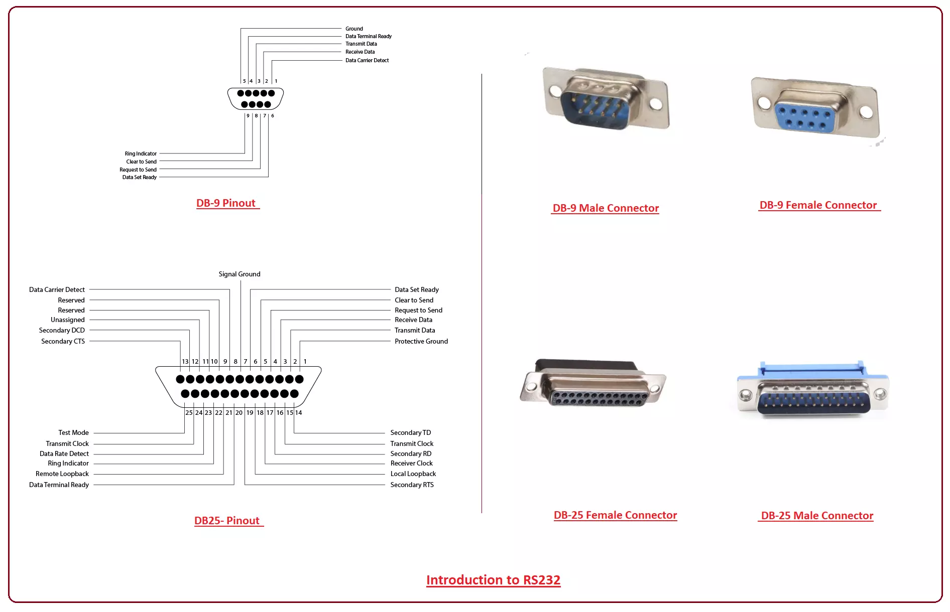
Hello Friends! Hope you are doing well. I am back to give you a daily dose of valuable information. Today, I'll discuss the detailed Introduction to RS 232 which is a standard communication protocol mainly used for serial communication between two devices. It was first introduced by the EIA (Electronic Industries Association) in 1960 to provide a pathway for connecting one device with other peripheral devices for flawless digital communication. It is true, that the inception of USB has grossly reduced the need for RS232 protocol, still, we can't brush off its significant importance in some industrial applications where Programmable Logic Controllers and Computerized Numerical Control Equipment are specifically programmed using RS 232 connectors which is nothing but an interface between DTE (Data terminal equipment) and (Data communication equipment). Don't worry about these abbreviations, I'll come to them later. In this post, I'll walk you through the basic concept of RS 232, why it is used and what are its main advantages and limitations. Let's dive in and explore the main features of the RS 232 protocol.

Introduction to RS232

RS 232, recently known as TIA 232, is a recommended standard protocol for serial data transmission between the electronic devices. It mainly works on three line signals: a transmission line, receive line and ground.
  • The transmission line is mainly used to send the data serially from one end and receive line accepts the data from the other end while the common ground is used for devices.
Initially, it was very difficult to devise the clear protocol to send the data from one end to another. This led to the inception of the RS 232 protocol, revitalizing the communication industry with the main purpose to keep both ends of the connecting device under the same roof where they can accept, understand and communicate in the same language. The RS 232 is mainly categorized into two systems: DTE and DCE. DTE is a data terminal equipment such as a computer that handles the communication with some control functions and plays the main part of the station. Similarly, DCE is a data circuit-terminal equipment that is placed on the other end of the station and understands data being communicated from the DCE equipment. The DCE system incorporates male DB connectors while the DCE system comes with female DB connectors.
  • RS232 data is bi-polar in nature, indicating an "ON or 0-state (SPACE) condition" if a voltage is around 3 to 12 V and features an "OFF" or 1-state (MARK) condition if voltage ranges from -3 to -12 V.
It is important to note that, most of the companies have reshaped the internal structure of the recent computers where they still indicate an OFF state at the zero voltage level, all the while ignoring the negative voltage. Similarly, the "ON" state is not necessarily dependent on the highest voltage level and can be achieved with much less voltage around 5V. Serial communication is mainly based on logical terms and RS232 transfers one bit at a time in the stream of ones and zeros which at the other end eventually get converted back to bits. There are eight bits in one byte.
  • The duration at which the required signal stays in the particular state is dependent on the baud rate. The communication carried out in a RS 232 protocol is measured in baud - A number of bits transferred per second i.e. 1000 baud indicate 1000 bits per second.
There are other parameters that must be set up before the data transmission: Length of the byte, Parity and magnitude of stop bits. This length of the signal can be reserved anywhere from 5 to 8 bits. The second parameter is important. Partiy mainly comes with five options
  • Even
  • Odd
  • Mark
  • Space
  • None
Even parity indicates the last data bit transmitted will be a logical 1 if it contains an even number of 0 bits. Similarly, Odd parity will be showing that the transmitted data is termed as logical 1 if it comes with an odd number of 0 bits. And MARK and SPACE parity will be representing that the last transmitted data bit will be logical 1 and 0 respectively. The last parameter is a number of stop bits and its value is set as 1 or 2. Transmission Capability RS-232 can perform transmission at data rates up to 20 Kbps with distance range capability around 50 ft. It all depends on the capacitance of the cable. The low capacity cables can transfer data up to 1000 ft while cables with high capacitance can transfer data at the lower distance.
  • As mentioned earlier many computers don't come with RS 232 port anymore, therefore we need to add USB-to RS 232 converter externally in order to make them compatible with RS 232 peripheral devices.
Although excessive use of RS 232 becomes obsolete, they are still used in low speed wired data connection and point-to-point networking equipment with short range capabilities.
Communication Process
The communication is simply based on the transmission and receive protocol and a total of 9 pins are involved in carrying out the complete transmission. The following figure shows how the data is transmitted over the terminal. Mainly the communication is laid out between DTE and DCE terminals over the mutual agreement for required data transfer. The RTS pin shows the desire to send data to another terminal. As it turns ON, it indicates the DTE terminal is ready to transfer the data. The data will be transmitted gradually over the line without any resistance if CTS pin from the other is activated and grants permission to DTE for data transfer.
  • The CD pin represents the current status of the RTS pin. If CD pin remains turned OFF, it will show the DTE terminal is not ready to send data over the channel. Similarly, turning it ON will be showing the DTW desires to send data and looking for permission from the other end.
Once the permission is granted, two other pins RD and TD come into play where former is used to receive data from DCE terminal and later is used for transferring data from DTE to DCE terminal.
  • The DTR pin must be turned ON before both terminals are ready to communicate with each other. Actually, DTR (Data Terminal Ready) will be indicating that entire arrangement from both terminals is adequate and matches with the required protocol for data transfer. It serves as a go-ahead signal for the communication.
Connector Pinout
Following figure shows the configuration of DB 25 connector. Following figure shows the pin configuration of the DB-9 connector.
  • DB-9 and DB-25 connectors offer the outstanding quality and reliability for a number of serial and parallel (IEEE 1284) applications.
Types of Serial Communication
There are two main types of serial communication. Half Duplex Full Duplex Half Duplex, as the name suggests, transfers the information in one direction only. It comes with two lines where one is a data line and other is signal ground. In this communication, the terminal is capable to send or receive data, but not at the same time. This method is an old one and is not under practice anymore. Full Duplex communication can transmit and receive data in both directions, requiring three main lines: data transmit line, data receive line and signal ground.
Applications
Before USB came into play, RS-232 ports were the part and parcel for data communication between a computer and other peripheral devices. Still, they are successful in grooving their way in many science and technology applications. Let's have a look.
  • In the absence of any network connection, RS232 ports are used to communicate in headless systems.
These ports play a vital role in establishing communication between the computer and embedded systems. Some Programmable Logic Controllers cannot be programmed without RS232 protocol.
  • Many Computerized Numerical Control Systems are equipped with RS232 port.
Apart from DB9 and DB25 ports, sometimes the two-wire interface is enough when the transmission of data is carried out in one direction only. Some GPS receiver and Digital Postal Scale work on this principle.
  • Similarly, two more lines RTS and CTS are included in a 5-wire version as per the technical needs where two-way data transmission layered with hardware flow control is required.
That's all for today. I hope you have got valuable information out of this read. If you are unsure or have any question, you can approach me in the comment section below. I'll try and help you the best way I can. You are most welcome to keep us updated with your feedback and suggestions, they help us provide you quality work as per your needs and requirements Thanks for reading the article.

ESP8266 Pinout, Datasheet, Features & Applications

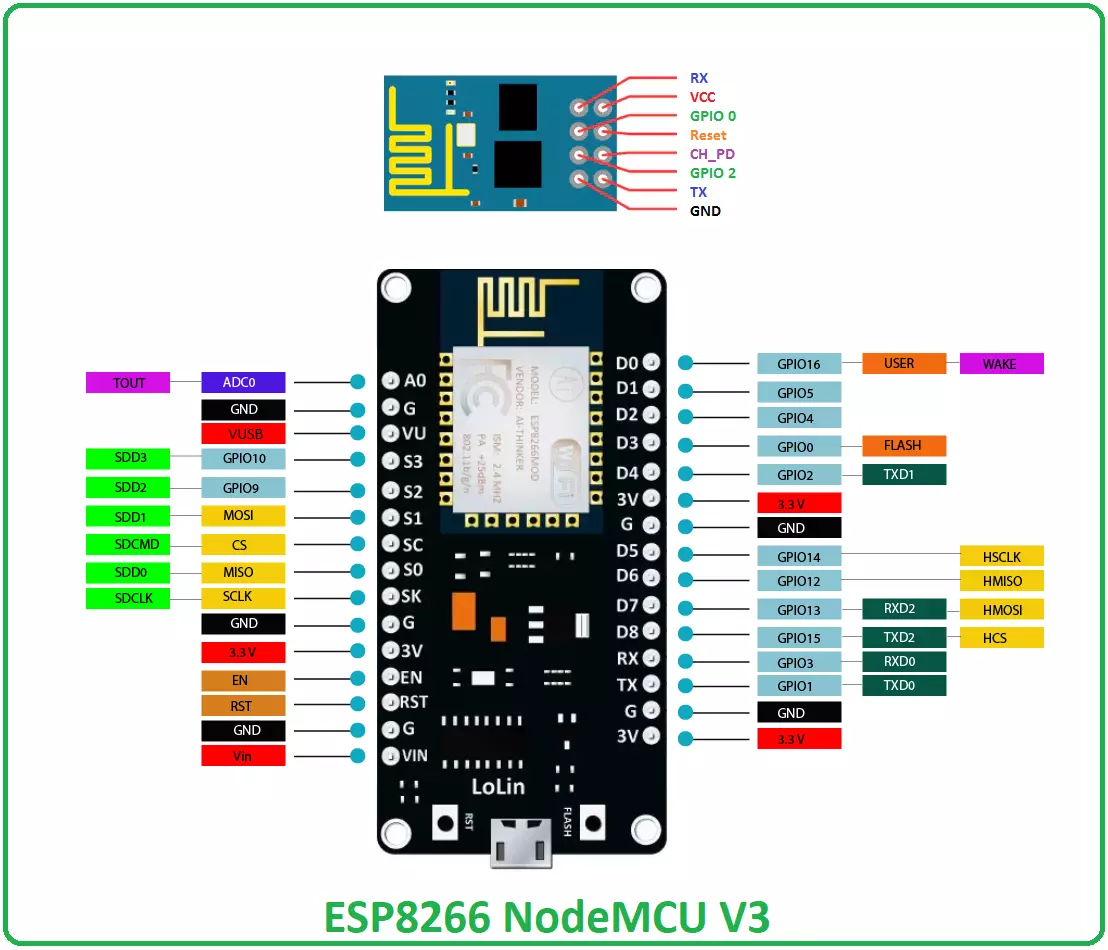
Hello friends! Hope you are doing well. Today, we will have a look at the detailed Introduction to ESP8266 WiFi module. ESP8266 is a very low-cost & user-friendly WiFi module, which develops a simple TCP/IP connection and can easily be interfaced with microcontrollers via Serial Port. The first chip in this series was ESP-01 which gained sheer attention in the market. In this tutorial, we will discuss the ESP8266 WiFi module along with its pinout, features, specifications, applications and datasheet. Let's dive in and nail down everything related to this device.

ESP8266 WiFi Module

  • ESP8266 (also called ESP8266 Wireless Transceiver) is a cost-effective, easy-to-operate, compact-sized & low-powered WiFi module, designed by Espressif Systems, that supports both TCP/IP and Serial Protocol.
  • It's normally used in IOT cloud-based embedded projects and is considered the most widely used WiFi module because of its low cost and small size.
  • It runs at an operating voltage of 3V and can handle a maximum voltage of around 3.6 V, so an external logic level converter is required if you are using 5V supply.
  • ESP8266 WiFi module can easily be interfaced with microcontrollers board (i.e. Arduino UNO) via Serial Port.
  • There are numerous breakout boards available based on ESP8266 WiFi Module (i.e. ESP8266 NodeMCU V3).
  • Beause of its compact size, its mostly used in autonomous projects (i.e. Robotics).
  • Other than ESP8266, "Espressif Systems" has designed many other ESP WiFi modules, few of them are shown in below figure:
Now let's have a look at the ESP8266 Pinout, necessary for interfacing with microcontrollers.

ESP8266 Pinout

  • ESP8266 Pinout consists of 8 pins in total, which are given in below table along with their operation:
ESP8266 Pinout
No. Pin Name Working
1 RX Serial Receiver Pin
2 Vcc Power Pin (+3.3 V; can handle up to 3.6 V)
3 GPIO 0 General-purpose I/O No. 0
4 RST Reset
5 CH_PD Chip power-down
6 GPIO 2 General-purpose I/O No. 2
7 TX Serial Transmitter Pin
8 GND Ground
  • Each pin comes with a specific function associated with it where Vcc and GND are voltage source and ground respectively.
  • RX and TX are used for communication where TX is dedicated for data transmission and RX is used receiving data.

ESP8266 Datasheet

  • You can download ESP8266 Datasheet by clicking the below button:
Download ESP8266 Datasheet

ESP8266 Features

  • It is also known as a system-on-chip (SoC) and comes with a 32-bit Tensilica microcontroller, antenna switches, RF balun, power amplifier, standard digital peripheral interfaces, low noise receive amplifier, power management module and filter capability.
  • The processor is based on Tensilica Xtensa Diamond Standard 106Micro and runs at 80 MHz.
  • It incorporates 64 KiB boot ROM, 80 KiB user data RAM and 32 KiB instruction RAM.
  • It supports Wi-Fi 802.11 b/g/n around 2.4 GHz and other features including 16 GPIO, Inter-Integrated Circuit (I²C), Serial Peripheral Interface (SPI), 10-bit ADC, and I²S interfaces with DMA.
  • External QSPI flash memory is accessed through SPI and supports up to 16 MiB and 512 KiB to 4 MiB is initially included in the module.
  • It is a major development in terms of wireless communication with little circuitry. and contains onboard regulator that helps in providing 3.3V consistent power to the board.
  • It supports APSD which makes it an ideal choice for VoIP applications and Bluetooth interfaces.

How to Power Up the Module

  • You can power up the device with PC port using USB to Serial adaptor. The 2 AA  and LIPO batteries are equally handy for powering up the device.
  • It is advised to not power this device directly with 5V dev board. Doing so can severely affect the quality and overall performance of the device.

ESP8266 NodeMCU

  • There are numerous breakout boards designed by different companies, based on this ESP8266 WiFi module.
  • Among these breakout boards, ESP8266 NodeMCU is the most popular one.
  • Here's the Pinout Diagram of ESP8266 NodeMCU:

ESP8266 Projects & Applications

ESP8266 WiFi module is widely used in embedded projects and thus brings WiFi capability. Here's few ESP8266 Projects & Applications:
  • Wireless Web Server
  • Geolocation using ESP8266
  • Pressure Sensors on Railway Tracks
  • Air Pollution Meter
  • Temperature logging system
  • World’s smallest IoT project
  • Wi-Fi controlled robot
  • Humidity and temperature monitoring
  • M2M using ESP8266
That's all for today. I hope I have given you everything you needed to know regarding this WiFi module. If you are unsure or have any question, you can ask me in the comment section below. I'd love to help you in any way I can. You are most welcome to keep us updated with your suggestions so we keep providing quality work that resonates with your needs and demands. Thanks for reading the article.

Introduction to RJ45

Hi Guys! Hope you are doing well. We always strive to give the most relevant information as per your needs and demands. Today, I'll discuss the details on the Introduction to RJ45. It is a type of standard connector mainly used for data transmission. Almost all ethernet cables come with this connector on each end, and they, sometimes, known as RJ cables. The RJ in the connector stands for registered jack while 45 defines the number of interface standard. In this post, I'll cover each and everything related to RJ45, why it used, features, and main applications. Let's dive right in and nail down everything you need to know.

Introduction to RJ45

  • RJ45 is a type of connector, mainly used for Ethernet networking including connection with PC network cards, data switches, WiFi access points, and routers.
  • It is connected to each end of Ethernet cables and acts as the main source for transferring data. RJ stands for registered jack and ethernet cables are also known as RJ cables.
  • The most common standard for RJ cables is known as CAT5 (Category 5)
  • In simple words, connectors at the end of ethernet cables are known as RJ45 connectors which also indicate how the cables are wired, while ethernet cables are termed as CAT5 (also RJ cables) which show the maximum speed the cable can attain.
  • RJ connector comes with eight pins which indicate it can house eight wires inside. All these wires come in different colors i.e four are in solid color while the remaining four are stripped. These wires are combined in twisted pairs that help in reducing the crosstalk and canceling EMI.
  • These cables are not shielded and are merely twisted for noise reduction.
  • CAT cables are mostly used in networking and can handle bandwidth around 100mbps.
  • These cables fail to work in high-speed environments, in that case, CAT5 is widely replaced by CAT6.
  • RJ45 cables deem feasible for both long and short distance, and apart from supporting ethernet protocol, they also work for ATM and serial ISDN T1 and E1.
  • RJ45 come with 8 wires and only 4 of them take part in the communication where pin 1 and 2 are used for data transmission while pin 3 and 4 are used for receiving data. (only in ethernet interface)
  • In serial and ISDN protocols, all pins take part in the communication and are wired in a straight through configuration.
  • Don't get confused between RJ connectors and RJ ports. Both are the part of RJ protocol where connectors serve as a (male) connector and port that receives the connector is known as (female) port.
 RJ45 Pinout and Wiring Standards
RJ cables are wired in two ways named T-568A and T-568B. Wiring standards in both of them are different and listed below.
  • Both wiring schemes are equally practiced and commonly supported by most of the devices, however, T-568A is preferred over other.
Following figure shows the pinout of RJ45 (T-568A). Following figure shows the pinout of the RJ45 (T-568B).
  • In some networking applications, crossover ethernet cable is a prerequisite which contains T-568B at one end and T-568A on the other end.
  • This cable is mainly used in computer-to-computer connections.
Difference between RJ45 and RJ11
  • Both connectors are different in terms of size, wires, and applications.
  • RJ45 is relatively large as compared to RJ11 and mainly used to build a connection with routers, computers, XBoxes, hardware firewalls and play stations. It comes with 8 wires.
  • While RJ11 is smaller in size, comes with 4 wires and mainly used for connection with telephone, modem, and fax machine.
  • Although RJ11 comes in smaller size and can fit in the RJ45 slot, however, it is not recommended to use this practice. Doing so can damage the slot and affect the overall working of the device in which it is plugged in.

Types of Ethernet Cables

Ethernet cables are widely used for telecommunication and networking purpose. They come in different types based on nature and data transmission speed they can carry along the length of the wire. RJ45 connectors are connected on both sides of the cables that act as a source of data transmission. Following are the main types of Ethernet cables used for networking and telecommunication purpose. CAT-1. It stands for category 1 that doesn't support TIA (telecommunication industries association). It is mainly used for standard telephone wiring and ISDN. CAT-2. Similar to CAT-1, this type of wiring is not recognized by TIA. It is mainly used for token ring wiring and capable of carrying data at the rate of 4Mbit/s. This is the old version of cable wiring and widely abandoned by advanced cable categories. CAT-3. This cable wiring is widely supported and recognized by TIA/EIA. It is mainly used for data networks and can carry data at the rate of 100Mbit/s. However, this type of wiring is also becoming obsolete because of less data transmission speed and frequency for carrying out different functions at the decent pace. CAT-4. This type of cable wiring is not supported by TIA. It is widely used for token ring networks with the capability of supporting frequency up to 20MHz. CAT-5. Category 5 cables were introduced with the intention of providing more speed as compared to their predecessors. They can transmit frequency up to 100MHz and are not recognized by TIA. This cable wiring uses two twisted pair and is not recognized by TIA. The CAT-5 cable is not recommended for recent applications, however, it is useful for 100Base-T and 1000Base-T networks as it provides suitable speed and frequency for the data networks. CAT-5e. This cable wiring is almost similar to CAT-5 with some exemptions in terms of data transmission speed and TIA recognition. It is preferred for applications where speed is a major concern as it can support speed up to 125 Mbps. The physical appearance of this wiring is similar to CAT-5 and widely used for 100Base-T and 1000Base-T networks. CAT-6. This cable wiring is recognized by TIA and stays ahead of other ethernet cables in terms of performance and speed i.e. supports up to 10Gbps. They come with an outer foil or braided shielding and cover less space as they are tightly wound as compared to CAT-5 and CAT-5e. The shielding minimizes the crosstalk and noise and protects the twisted pair of wires inside the cable. They can work and cover a distance of around 55 meters. CAT-6a. It stands for Category 6 Augmented cable. They come with higher transmission speed, encompass maximum bandwidth and are less flexible than CAT-6 cables. They can carry more data along the length of the cable as compared to their predecessors and cover more distance without losing the bit of accuracy. The shielding is added in the wiring that protects the cable and helps in removing the crosstalk. CAT-7. It supports frequency up to 600 Mbps and comes with four individually shielded pairs. It works best in many applications for carrying out data transmission at a decent pace. They are introduced for rated speed of around 10 Gigabit. CAT-7a. These cables are used for augmented specifications that can support speed around 10 Gigabit. They cover frequency up to 1000 MHz and are quite identical to CAT-7 cables in terms of physical appearance and performance capability.

How to Connect Two Computers Using Ethernet Cables

It is very easy to connect two computers for data transmission using ethernet cables. The CAT-5 or CAT-5e crossover cables are widely used for this purpose and prevent from losing any data during transmission. These cables are quite identical to straight through cables but come with twisted wires on both ends. You can use the following steps to connect two computers using ethernet cables.
  • Connect one end of the cable with RJ45 connector into the ethernet port of the computer. Plug the other end of the cable into another computer.
  • Log in to one of the computers.
  • Go to the search box at the bottom left of the computer and type "Network and Sharing Center" and click it.
  • Then go to the "Change Adaptor Settings" on the top left side.
  • Right click on the "Ethernet" and go to properties.
  • Then select "Internet Protocol version 4 TCP/IPv4" and click properties.
  • Select the IP address and subnet mask at the two computers as mentioned below.
To check the connection, restart both PC and use the below instructions.
  • ping 192.168.0.2 -t: from the second PC
  • ping 192.168.0.1 -t: from the first PC
Right click on this PC option and click on "Change Settings" option.
  • The "Workgroup" name should be identical in both PC, otherwise, ethernet connection won't work.
  • If you want to share whole drive, just right click on the drive you want to share and select share with "Advanced Sharing Options" and check the box beside share this folder option and click "OK" to apply changes.
Applications
  • RJ45 are mainly used in ethernet cables for data transmission. They come in two types i.e. T-568A and T-568B.
  • As compared to the RJ11 connector, RJ45 comes with more applications including ethernet networking, industrial automation, and telecommunications.
That's all for today. I hope I have given you everything you need to know about RJ45. However, if you are feeling skeptical or have any question, you can approach me in the comment section below. I'd love to help you in any way I can. Feel free to keep us updated with your valuable feedback and suggestions, they help us provide you quality work so you keep coming back for what we have to offer. Thanks for reading the article.
Syed Zain Nasir

I am Syed Zain Nasir, the founder of <a href=https://www.TheEngineeringProjects.com/>The Engineering Projects</a> (TEP). I am a programmer since 2009 before that I just search things, make small projects and now I am sharing my knowledge through this platform.I also work as a freelancer and did many projects related to programming and electrical circuitry. <a href=https://plus.google.com/+SyedZainNasir/>My Google Profile+</a>

Share
Published by
Syed Zain Nasir