Web-Server Based Weather Monitoring System Using ESP32

Abstract: This paper is written to represent a web-server based real-time weather monitoring system implemented using the ESP32 module. The system is designed to measure the weather conditions like temperature, pressure, humidity etc, in its vicinity. This system continuously provides real-time data (weather conditions) over limited or controlled areas, for example, agriculture fields, homes or a particular room, industries etc. Although we have satellites for weather monitoring but to perform research over a particular area, the data observed should be highly accurate which is not possible with satellites. To implement an IoT network we need to use a webserver to continuously store and display the real-time data which can be accessed globally. ’ThingSpeak’ is a web service where one can upload and access (globally) with internet-connected devices. ESP32 will be acting as an interface medium between the various sensors and the web-server. ESP32 module is also responsible for collecting, processing and then communicating the data to the server. The real-time data stored on the web server can be further used for research and analysis of weather conditions of a particular place.

Keywords

ESP32, IoT, Temperature sensor, Humidity sensor, Pressure sensor, Altitude sensor, Arduino IDE, ThingSpeak.

Where To Buy?
No.ComponentsDistributorLink To Buy
1ESP32AmazonBuy Now

Introduction

The evolving generation of wireless technology has made human life a lot easier. Where everything is online and automatic we can easily monitor multiple things virtually from anywhere in the world. The WSN (wireless sensor networks) and Internet of things or IoT play an important role in implementing and accessing these wireless technologies. Smart homes, smart cities and smart weather monitoring systems are examples of such technologies where things are quite simpler or easier.

In this web-server based weather monitoring system, the weather data (from the surrounding environment or of a particular location) like temperature, humidity, pressure etc. is measured with the help of some sensors and then the collected data will be stored on a server after being processed by a microcontroller. Our daily activities are inseparable from weather conditions and various environmental factors. The real-time data collected can be used in research and analysis and the results can be helpful in human life and for improving environmental conditions as well.

The Internet of Things is a system made up of multiple inter-related computing devices. The main factor ‘things’ in IoT is designated to a component that is capable of communicating data over a network (IoT), the thing could be animals, a digital machine, a sensor, a human being etc. Each component of the Internet of Things network is given an individual or a distinct identity and the ability to communicate data or information over a wireless network that is too without the intervention of a human or a computer [8].

An interface medium capable of collecting, controlling, and communicating data among transmitter and recipient electronic equipment or servers is required to build the IoT network[9].

The ESP32 microcontroller series was developed by Espressif Systems. This module (the ESP32) includes a 2.4GHz Wi-Fi chip, memory, a 32-bit Tensilica microcontroller, an antenna, peripheral interfacing abilities, power management modules, and more. This ESP32 module is excellent for the Internet of things because of all of its technological and infrastructural aspects [10].

DHT11 and BMP280 sensors are used to collect the data from their surrounding environment and then communicate the data to the ESP32 module over a particular protocol [11].

The application of this weather monitoring system can also play an important role in the field of agriculture[12 ] to increase productivity, research application, and reducing manpower (by reducing the need to manually monitor the field status). Sometimes in a particular agricultural zone that is hazardous for a human beings, it is quite difficult to manually (offline) monitor the environment or weather conditions. In such cases, this web server based or online weather monitoring system can be of great importance.

Fig. 1

Hardware and Software Components

The list and quantity of the components required to implement the web server based weather monitoring system are shown in Table1.

Table: 1

DHT11

Fig. 2 DHT11 sensor

DHT11 sensor (or temperature and humidity sensor) is a sensor module used to measure humidity and temperature from its surrounding. This sensor module is responsible for monitoring the ambient temperature and humidity of a given area. An NTC (negative temperature co-efficient) temperature sensor and a resistive type humidity sensor make up the sensor. An 8-bit microcontroller is also included. The microcontroller performs ADC (analogue to digital conversion) and outputs a digital signal via the single wire protocol [13].

Some of the technical specifications of the DHT11 sensor are:

Table:2  DHT11 technical specifications

DHT11 sensors can also be used to create a wired sensor system with up to 20 meters of cable.

To measure temperature and humidity, two DHT modules (DHT11 and DHT22) are available on the market. Both modules serve the same purpose, but they have different specifications. The DHT22 sensor, for example, has a wider range of temperature and humidity sensitivity. However, DHT22 is more expensive than DHT11. As a result, you can choose to use any of the modules as per your needs.

Interfacing DHT11 with ESP32[14]

Table.3  Interfacing DHT11 with ESP32

BMP280

Another sensor we are using is the BMP280. The BMP280, also known as the barometric pressure sensor, is a temperature, pressure, and altitude sensor. This sensor's small size and low power consumption make it suitable for mobile applications, GPS modules, and battery-powered devices, among other things[15].

The Bosch BMP280 is based on Bosch's validated ‘Piezo-resistive pressure sensor technology’, which features high accuracy, long-term stability, linearity, and EMC robustness.

The barometric pressure sensor (280) is the successor to the BMP180 sensor, and it is mostly preferred in all areas where precise temperature and pressure measurements are required.

Fig.3  BMP280 Sensor

Fitness, indoor navigation, and GPS refinement are all new technologies which require relative accuracy, and the BMP280 is ideal for them. This module is preferred over the other available modules for temperature records or measurement because of its low TCO (Temperature coefficient of Offset).

The temperature measured with the BMP280 sensor is more accurate than the DHT11 sensor. BMP80 provides a 0.01°C accuracy rate.

Some technical specifications of the BMP280 sensor are:

Table:4  BMP280 Technical specifications

ThingSpeak web service

A web server is a place where one can store data online and can access that data at any time and from anywhere in the world [16]. A real-time data is created with the help of a web-server. There are various web services available to store real-time data for research and analysis like AWS (Amazon Web Service), Azure, Firebase etc.

We are using the ThinSpeak web service provided by MathWorks which allows us to send sensor readings/data to the cloud. The ThingSpeak is an open source data platform for the Internet of Things (IoT) applications. We can also visualize and act on or access the data (calculate the data) sent to the ThingSpeak server from ESP32. Two different types of channels are available to store data on the ThingSpeak server namely ‘Public Channel’ and ‘Private Channel’ and one can use either of the available channels to store and display data [17].

ThingSpeak is frequently used for IoT prototyping and proof-of-concept systems that require analytics[18].

Software Used

We need to give instructions to our ESP32 module so that it can interface, read data from DHT11 and BMP280 sensors and then finally publish the collected data to the ThingSpeak server. Arduino IDE is an integrated development environment used to write, compile and debug the program for the ESP32 module[19].

Fig. Arduino IDE

Process Flow

The process flow of our weather monitoring system is shown below in Chart 1. The process starts with the initialization of ESP32 module which is acting as an interface medium between the sensor modules and the web-server. The ESP32 wi-fi module is continuously searching for the network credentials as per the instruction provided. After connecting to the internet the sensor modules will be initialized and the real-time data [22] collected from the surrounding environment will be pushed to the ThingSpeak web server[23].

Flow Chart: 1

Results

The results observed from the implemented weather monitoring system are shown below. We observed four different environmental conditions which include temperature, humidity, pressure and altitude. The sensor data collected by ESP32 from DHT11 and BMP280 sensors is published to the ThingSpeak web server. On ThingSpeak we have created a channel that contains four fields to store four different environmental factors temperature, humidity, pressure and altitude.

Fig. Hardware

In fig. 4 we can see the ‘Field 1’ which is containing the temperature readings published or communicated from the ESP32 module and saved on the ThingSpeak server.

Similarly, fields 2, 3, and 4 are displaying the humidity, pressure and altitude respectively.

Fig. 4 Temperature (°C)

Fig. 5 Humidity

Fig. 6 Pressure (hPa)

Fig. 7 Altitude

Each factor is monitored at different intervals of time to observe the variations in various environmental factors. From table 5 we can see the various environmental factors and their values at different time intervals for the approximate duration of 24hrs.

Table 5 Variations in weather conditions

Conclusion

We observed the weather conditions (that includes temperature, humidity, pressure and altitude) with our “Web-server based weather monitoring system using ESP32”. The observed real time data is stored on the ThingSpeak server which can be accessed globally. The different values of each (mentioned earlier) environmental factor at different intervals in time are also observed (given in table 5) and the observed result clearly shows the changes in the weather conditions for a full day cycle. Hence, we have successfully implemented and tested the web server based weather monitoring system with ESP32 and ThingSpeak web server.

References

  • Maier, A., Sharp, A. and Vagapov,  Y., November  “Comparative  analysis  and practical implementation  of  the  ESP32  microcontroller  module  for  the  internet  of things”  2017 .
  • Prisma Megantoro, Brahmantya Aji Pramudita, Vigneshwaran Pandi, “Real-time monitoring system for weather and air pollutant measurement with HTML-based UI application” June 2021.
  • Foughali Karim, Karim Fathallah, Ali Frihida, “Monitoring System using web of things in precision agriculture” 2017.
  • J.Shah and B. Mishra, “IoT enabled environmental monitoring system for smart cities,” in 2016 International Conference on Internet of Things and Applications (IOTA), 2016.
  • P.Susmitha , G. Sowmyabala, “ Design and Implementation of Weather Monitoring and Controlling System” July 2014.
  • S.Navulur, A. S. C. S. Sastry, M. N.  Giri Prasad,  “Agricultural  management  through  wireless  sensors  and internet of things” .
  • K.Siva, S. Ram, and A. N. P. S. Gupta, “IoT based Data Logger System for weather monitoring using Wireless sensor networks,” 2016
  • Ferdin Joe John Joseph, “IoT Based Weather Monitoring System for Effective Analytics”, 2249 – 8958, Volume-8 Issue-4, April, 2019.
  • A F Pauzi, MZ Hasan, “Development of IoT Based Weather Reporting System”, 2020.
  • ESP32-IoT Development Framework, https://www.espressif.com/en/products/sdks/esp-idf
  • Carlo Guarnieri Calo Carducci, Antonello Monti, Markus Hans Schraven, Markus Schumacher, Dirk Mueller, “Enabling ESP32 based IoT Applications in Building Automation Systems”, 2019.
  • R.K. M. Math and N. V Dharwadkar, “IoT Based Low-cost Weather Station and Monitoring System for Precision Agriculture in India”, 2018 (2nd International Conference on I-SMAC).
  • N. Tianlong, “Application of Single Bus Sensor DHT11 in Temperature Humidity Measure and Control System [J]”, 2010.
  • “Create a Web Server With ESP32”, https://www.theengineeringprojects.com/2021/11/create-a-web-server-with-esp32.html
  • ThinSpeak, https://thingspeak.com/pages/learn_more
  • T. Thilangam. J, T. S. Babu, and B. S. Reddy, “Weather monitoring system application using LabView”, 2nd International Conference on I-SMAC, 2018.
  • J.Weiss and R. Yu, "Wireless Sensor Networking for the Industrial Internet of Things".
  • Gaurav Verma, Pranjal Mittal, Shaista Farheen, “Real Time Weather Prediction System Using IoT and Machine Learning.
  • R.Shete, S. Agrawal, “IoT based Urban Climate Monitoring using Raspberry Pi”, International Conference on Signal Processing and Communication, 2016.

Reading Data from Firebase Database with ESP32

Internet of Things is a system of multiple inter-related computing devices. The factor ‘thing’ in IoT is designated to an entity capable of communicating data over a network (IOT), which can be a digital machine, sensor, human being, animals etc. Each component that is included in IoT network is assigned with an unique identity called UID and the ability to communicate data over IoT network without any external human or computer intervention.

Hello readers, I hope you all are doing great. In our previous tutorial, we discussed how to upload data to Firebase Real-time Database using ESP32. In this tutorial, we will learn how to read the data stored on the Firebase Database with ESP32.

We can access the data stored in Firebase database from anywhere in the world, which makes this preferable in IoT applications.

Where To Buy?
No.ComponentsDistributorLink To Buy
1ESP32AmazonBuy Now

Project overview

In our previous tutorial, we learnt how to upload an integer value (for demonstration) to Firebase real-time database. So, in this tutorial we will learn how to fetch or receive those integer values from Firebase database.

To access real-time data, we are using two ESP boards where one is used to upload/store the real-time data to the Firebase database and another to read the data stored on the firebase.

Although, it is not required to use two ESP boards, we can also access the previously saved data on the Firebase database with only a single ESP32/ESP8266 board.

We can use the same code for both ESP32 and ESP8266 but we need to make some changes like some of the libraries will be different for ESP8266 and the selection of ESP8266 development board while uploading the code with Arduino IDE.

Fig. 1 Reading data from firebase

Firebase

Google's Firebase real-time database is a development platform that includes a number of services for managing and authenticating data.

Firebase is a mobile and web app development platform (that also works well with Android APIs) that includes features such as Firebase Cloud, real-time data, and Firebase authentication, among others.

According to Firebase's official documentation (https://firebase.google.com/docs/database), when a user creates a cross-platform application using JavaScript SDKs for Android or Apple, all clients share a single database.

Fig. 1 Firebase Real-time database and ESP32

The following are the main features of the Firebase Real-time database:

  • Firebase applications remain responsive even when they are not connected to the internet. If any changes were missed while in offline mode, they will be automatically synchronized once connectivity is restored.
  • Unlike hypertext transfer protocol requests, Firebase RTDB uses data synchronization to update changes in the database within milliseconds, making it easier to access the database from a web browser or a mobile device.

Firebase in IoT:

The Internet of Things, also known as IoT, is the interconnection of physical objects or devices with sensors and software accessing capabilities in order to communicate data or information over the internet.

We need an interface medium that can fetch, control, and communicate data between sender and receiver electronics devices or servers in order to build an IoT network.

The Firebase real-time database gives you a place to store data from sensors on your level device. With Android APIs, Firebase performs admirably.

Firebase is especially useful for storing data from sensors and syncing it between users in real-time in data-intensive Internet of things (IoT) applications. For the sake of simplicity and clarity, we can say that it is a Google cloud service for real-time collaborative apps.

Components required:

  • ESP32 development board
  • Arduino IDE for programming
  • Firebase account
  • Firebase API key and project URL

Programming with Arduino IDE

We are using Arduino IDE to compile and upload code into the ESP32 module. You must have ESP32 board manager installed on your Arduino IDE to program the ESP32 module. To know more about Arduino IDE and how to use it, follow our previous tutorial i.e., on ESP32 programming series. The link is given below:

https://www.theengineeringprojects.com/2021/11/introduction-to-esp32-programming-series.html

Steps to add the necessary libraries in Arduino IDE:

  • Go to Tools >> Manage Libraries.

Fig. 2 manage libraries

  • Search for the Firebase ESP Client library in Library Manager and click Install.
  • We are attaching an image, where we are installing the Firebase ESP-Client (2.3.7 version) library.

Fig. 3 Install Firebase ESP Client Library

Firebase API key and Project URL

We have already posted a tutorial on our website on getting started with Firebase real-time database and how to post or upload data to Firebase database from ESP32. Where we discussed, how to create a project on Firebase real-time database, authentication, how to access the API key and project URL etc.

So now we do not need to create a new project, we are using the same project and hence same API key and project URL to read or download the data from Firebase real-time database.

  • To access the project API key, go to Firebase website and open the project you have created.
  • Go to left sidebar >> setting >> project setting and copy the Web API key.
  • Paste that API key in your Arduino IDE code.

Fig. 4 Project Setting

Fig. 5 Project API key

  • Got to Real-time database on left sidebar and copy the project URL.
  • Paste the project URL in your Arduino IDE code.

Fig. 6 Project URL


Code

//--add necessary header files

#include <WiFi.h>

#include <Firebase_ESP_Client.h>

#include "addons/TokenHelper.h" //Provide the token generation process info.

#include "addons/RTDBHelper.h" //Provide the real-time database payload printing info and other helper functions.

// Insert your network credentials

#define WIFI_SSID "ssid"

#define WIFI_PASSWORD "password"

// Insert Firebase project API Key

#define API_KEY "replace this with your project API key"

// ----Insert real-time database URL

#define DATABASE_URL "replace this with your project URL"

//Define Firebase Data object

FirebaseData fbdo;

FirebaseAuth auth;

FirebaseConfig config;

unsigned long sendDataPrevMillis = 0;

int read_data;

bool signupSuccess = false;

void setup() {

Serial.begin(115200);

WiFi.begin(WIFI_SSID, WIFI_PASSWORD);

Serial.print("Connecting to Wi-Fi");

while (WiFi.status() != WL_CONNECTED) {

Serial.print(".");

delay(200);

}

Serial.println();

Serial.print("Connected to... ");

Serial.println(WiFi.localIP());

Serial.println();

// Assigning the project API key

config.api_key = API_KEY;

//Assign the project URL

config.database_url = DATABASE_URL;

/// check signup statue

if (Firebase.signUp(&config, &auth, "", "")) {

Serial.println("ok");

signupSuccess = true;

}

else {

Serial.printf("%s\n", config.signer.signupError.message.c_str());

}

// Assign the callback function for token generation task

config.token_status_callback = tokenStatusCallback;

Firebase.begin(&config, &auth);

Firebase.reconnectWiFi(true);

}

void loop()

{

if (Firebase.ready() && signupSuccess && (millis() -

sendDataPrevMillis > 8000 || sendDataPrevMillis == 0))

{

sendDataPrevMillis = millis();

if (Firebase.RTDB.getInt(&fbdo, "/test/int"))

{

if (fbdo.dataType() == "int")

{

read_data = fbdo.intData();

Serial.print("Data received: ");

Serial.println(read_data); //print the data received from the Firebase database

}

}

else

{

Serial.println(fbdo.errorReason()); //print he error (if any)

}

}

}

Code Description

  • The libraries we are using are:
    • The first one is h, which is used to enable the Wi-Fi module and hence wireless network connectivity.
    • Another library we are using is the h which is responsible for interfacing ESP32 and Firebase Real-time Database.

Fig. 7 Header files

  • We also need to add two helper libraries (required by the Firebase library).
  • The TokenHelper library is responsible for managing the token generation process.
  • On the other hand, the RTDBHelper library is responsible for providing helper functions to print data coming from the Firebase database.

Fig. 8 Helper libraries

  • Next, we need to insert the project API key obtained from the Firebase project setting page.

Fig. 9 Insert API key

  • Similarly, insert the RTDB (real-time database) URL.

Fig. 10 RTDB URL

  • Next, we are defining three firebase data objects, responsible for linking App to Firebase.

Fig. 11 Firebase Data Objects

  • Enter the network credentials in place of SSID and PASSWORD.

Fig. 12 Enter Network credentials

Setup

  • Initialize the serial monitor at 115200 baud rate for debugging purpose.
    • begin() function is used to initialize the Wi-Fi module with Wi-Fi credentials used as arguments.
    • The While loop will continuously run until the ESP32 is connected to Wi-Fi network.

Fig. 13 Initialize wifi module

  • If the device is connected to local Wi-Fi network then print the details on serial monitor.
  • localIP() function is used to fetch the IP address.
  • Print the IP address on serial monitor using println() function.

Fig. 14 Fetch/obtain the IP address

  • Here, we are assigning the API key to the firebase configuration.

Fig. 15 configuring API key

  • Similarly, the database URL is also assigned to firebase configuration

Fig. 16 configuring database URL

  • Next, we are checking or verifying the Firebase sign-up status.
  • In the signup() function the last two arguments are empty, indicating the anonymous user.
  • If you have enabled different sign-up methods during the Firebase authentication method like Google account, Facebook etc then you need to add the respective credentials as arguments.
  • The respective results of signup status will be printed on the serial monitor.

Fig. 17 sign up status

  • Next, you need to assign the callback function for token generation.

Fig. 18

Loop()

  • Once the signup is successfully done, we are ready to fetch the data stored on the Firebase real-time database in every 10 seconds.
  • RTDB.getInt() command is used to store the data in /test/int node. But before that we are checking the data type that is ‘int’(integer). If the data type of the message/data received from Firebase RTDB is ‘int’ only then the data will be stored inside the integer type variable i.e., “read_data”.

Fig. 19 Fetch data from Firebase RTDB

  • If the data type is other than integer then an error will be printed on the serial monitor.

Fig. 20

  • Similarly, we can read/fetch various types of data like float, string, array etc. from the firebase database.

Testing

  • Open your Arduino IDE and paste the above code.
  • Change the network credentials, that is the SSID and PASSWORD as per you network setup.
  • Compile and upload the code into ESP32 development board.
  • Before uploading the code make sure that you have selected the correct development board and COM port.

Fig. 21 Select development board and COM port

  • Once the code is uploaded successfully, open the Serial monitor and select the 1115200 baud rate (as per your code instructions).
  • Make sure Wi-Fi to which your ESP device is supposed to connect is ON.
  • Once your ESP device is connected with Wi-Fi, you should see the data fetched from Firebase, printing on the serial monitor with a particular delay (as per the code instructions).

Fig. 22 Data sent Vs Data Received

This concludes the tutorial. I hope you found this of some help and also hope to see you soon with a new tutorial on ESP32.

ESP32 Firebase

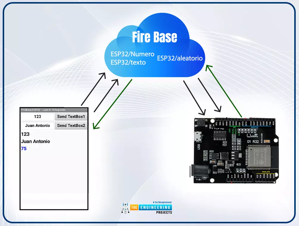
Hello readers, I hope you all are doing great. In this tutorial, we will learn how to access Firebase (a real-time database) to store and read values or data with ESP32.

It is Google’s mobile application development platform that can be used to can access, monitor and control ESP32 from anywhere in the world with its (firebase) real-time database.
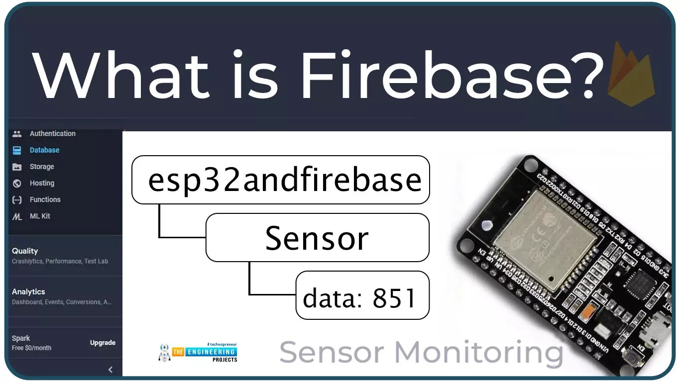
Where To Buy?
No.ComponentsDistributorLink To Buy
1ESP32AmazonBuy Now

What is Firebase?

Firebase real-time database is a development platform provided by Google which included multiple services to manage and authenticate data.

Firebase is basically a mobile and web app development platform I as works great with Android APIs) that includes features like firebase cloud, real-time data and Firebase authentication etc.

As per Firebase’s official documentation (https://firebase.google.com/docs/database), whenever a user creates a cross-platform application like with Android, or Apple, JavaScript SDKs, all the clients share a single.

Fig. 1 Firebase Real-time database and ESP32

The main features of the Firebase Real-time database are:

  • Firebase applications remain responsive even in offline mode. If any changes are missed during the offline mode, then after the connectivity is reestablished those changes will be automatically synchronized.
  • Firebase Real-time database makes it easier to access the database from a web browser or a mobile device.
  • Unlike hypertext transfer protocol requests, Firebase RTDB uses data synchronization which makes it possible to update the changes in the database within milliseconds.

Role of Firebase Realtime Database in IoT

The IoT or Internet of Things is the interconnection of physical objects or devices with sensors and software accessing capabilities to communicate data or information over the internet.

To build an IoT network, we need an interface medium that can fetch, control, and communicate data between sender and receiver electronics devices or servers.

Firebase real-time database provides a platform to store data collected from sensors at the level device. Firebase works great with Android APIs.

Firebase is particularly useful in data-intensive Internet of things (IoT) applications to store from sensors and synch that data between users in real-time. For simplicity or better understanding we can say that it is a cloud service provided by Google for real-time collaborative apps.

Project Overview

  • In this tutorial we are going to create a Firebase project with real-time database to read and store data with ESP32. Steps included to achieve the target are; creating a firebase project, storing data from ESP32 to firebase real-time Database, Reading data from firebase real-time database with ESP32.

Prerequisites

  • ESP32 development board
  • Arduino IDE
  • Necessary Library (Firebase ESP Client)
  • A Google account to access Firebase
 

Getting Started with Firebase

  • Create a project

The steps involved in creating a Firebase project are:

Fig. 2 Get started

  • Click on Create a project.

Fig. 3 Create a project

  • Assign a name to your project and accept the terms and conditions then click on the continue

Fig. 4 project name

  • Disable the “Enable Google Analytics” option and click on real-time.

Fig. 5 Enabling Google Analytics

  • Now your project is ready click the

Fig. 6 Project Created successfully

Authentication

    • Next we need to set the authentication methods for the app.

As per the official firebase documentation at: https://firebase.google.com/docs/auth , the identity of a user is required by most online services or mobile applications or we can say , it handles authentication process and logging in (in this tutorial, the ESP32). Getting to know the identity of a user enables an application to save user data securely in the cloud and provide a consistent personalized service across all of the customer's devices (android phones, computers, applications etc).

  • Click on

Fig. 7 Authentication

  • You will be redirected to a new page, click on ‘get started.
  • There are multiple methods available to authenticate you account, as shown below.
  • Select any of the authentication method.

Fig. 8 Select authentication method

Next thing is creating a real-time database for the project.

  • Creating a Real-time Database
    • Click on the Real-time database given at the left sidebar.

Fig. 9 Real-time database

  • Then, click on Create Database.

Fig. 10 Creating database

  • Select your nearest location.

Fig. 11

  • Select the Start in test mode option and click on enable

Fig. 12 select location

  • Now your database is successfully created. You will be redirected to a new page containing the database URL.
  • Copy the URL and paste in your ESP32 code.
  • Now the next requirement is getting the API key.

Project API

    • Go to left sidebar and click on Project Overview and then project setting.

Fig. 13 Accessing project API key

  • Copy the web API key and paste in your ESP32 code.
  • That’s all about creating a Firebase account, project, and verification. Now, we are ready to interface the database and ESP32 module.

Programming with Arduino IDE

We are using Arduino IDE to compile and upload code into the ESP32 module. You must have the ESP32 board manager installed on your Arduino IDE to program the ESP32 module. To know more about Arduino IDE and how to use it, follow our previous tutorial i.e., on ESP32 programming series. The link is given below:

https://www.theengineeringprojects.com/2021/11/introduction-to-esp32-programming-series.html

Steps to add the necessary libraries in Arduino IDE:

  • Go to Tools >> Manage Libraries.

Fig. 14 manage libraries

  • Search for the Firebase ESP Client library in Library Manager and click Install.
  • We are attaching an image, where we are installing the Firebase ESP-Client (2.3.7 version) library.

Fig. 15 Install Firebase ESP Client Library

Arduino IDE Code ( To store data from ESP32 to Firebase Database)

//--add necessary header files

#include <WiFi.h>

#include <Firebase_ESP_Client.h>

#include "addons/TokenHelper.h" //Provide the token generation process info.

#include "addons/RTDBHelper.h" //Provide the real-time database payload printing info and other helper functions.

// Insert your network credentials

#define WIFI_SSID "replace this with your netwrok SSID"

#define WIFI_PASSWORD "replace this with your wi-fi password"

// Insert Firebase project API Key

#define API_KEY "replace this with your API key"

// ----Insert real-time database URL

#define DATABASE_URL "replace this with your project URL"

//----Define Firebase Data object

FirebaseData fbdo;

FirebaseAuth auth;

FirebaseConfig config;

int value = 10;

bool signupSuccess = false;

unsigned long sendDataPrevMillis = 0;

void setup()

{

Serial.begin(115200);

WiFi.begin(WIFI_SSID, WIFI_PASSWORD);

Serial.print("Connecting to Wi-Fi");

while (WiFi.status() != WL_CONNECTED){

Serial.print(".");

delay(100);

}

Serial.println();

Serial.print("Connected with IP: ");

Serial.println(WiFi.localIP() );

Serial.println();

// Assign the api key ( required)

config.api_key = API_KEY;

// Assign the RTDB URL ( required)

config.database_url = DATABASE_URL;

// Sign up status

if (Firebase.signUp(&config, &auth, "", ""))

{

Serial.println("ok");

signupSuccess = true;

}

else{

Serial.printf("%s\n", config.signer.signupError.message.c_str());

}

/* Assign the callback function for the long running token generation task */

config.token_status_callback = tokenStatusCallback; // see addons/TokenHelper.h

Firebase.begin(&config, & auth);

Firebase.reconnectWiFi( true);

}


void loop()

{

if (Firebase.ready() && signupSuccess && (millis() - sendDataPrevMillis >

10000 || sendDataPrevMillis == 0))

{

sendDataPrevMillis = millis();

if (Firebase.RTDB.setInt(&fbdo, "test/int", value))

{

Serial.println("PASSED");

Serial.println("PATH: " + fbdo.dataPath());

Serial.println("TYPE: " + fbdo.dataType());

}

else

{

Serial.println("FAILED");

Serial.println("REASON: " + fbdo.errorReason());

}

value++;

}

}

Before uploading the code in ESP32 board there are some changes you need to make which includes:

  • Adding network credentials
  • Inserting API key
  • Inserting Firebase project URL
  • Installing necessary library files

Code Description

  • The libraries we are using are:
    • The first one is h, which is used to enable the Wi-Fi module and hence wireless network connectivity.
    • Another library we are using is the h which is responsible for interfacing ESP32 and Firebase Real-time Database.

Fig. 16 Header files

  • We also need to add two helper libraries (required by the Firebase library).
  • The TokenHelper library is responsible for managing the token generation process.
  • On the other hand, the RTDBHelper library is responsible for providing helper functions to print data coming from the Firebase database.

Fig. 17 Helper libraries

  • Next, we need to insert the project API key obtained from the Firebase project setting page.

Fig. 18 Insert API key

  • Similarly, insert the RTDB (real-time database) URL.

Fig. 19 RTDB URL

  • Next, we are defining three firebase data objects, responsible for linking App to Firebase.

Fig. 20 Firebase Data Objects

  • Enter the network credentials in place of SSID and PASSWORD.

Fig. 21 Enter Network credentials

  • Next, we are defining some variables to store integer value, status of sign up to firebase account, and delay element etc.

Fig. 22 variable declaration


Setup

  • Initialize the serial monitor at 115200 baud rate for debugging purpose.
    • begin() function is used to initialize the Wi-Fi module with Wi-Fi credentials used as arguments.
    • The While loop will continuously run until the ESP32 is connected to Wi-Fi network.

Fig. 23 Initialize wifi module

  • If the device is connected to local Wi-Fi network then print the details on serial monitor.
  • localIP() function is used to fetch the IP address.
  • Print the IP address on serial monitor using println() function.

Fig. 24 Fetch/obtain the IP address

  • Here, we are assigning the API key to the firebase configuration.

Fig. 25 configuring API key

  • Similarly, the database URL is also assigned to the firebase configuration

Fig. 26 configuring database URL

  • Next, we are checking or verifying the Firebase sign-up status.
  • In the signup() function the last two arguments are empty, indicating the anonymous user.
  • If you have enabled different signup methods during the Firebase authentication method like Google account, Facebook etc then you need to add the respective credentials as argument.
  • The respective results of signup status will be printed on the serial monitor.

Fig. 27 sign up status

  • Next, you need to assign the callback function for token generation.

Fig. 28

Loop()

  • If, the sign up status is true (or Successful), then we are ready to send the data from ESP32 to Firebase Real-time database.
  • For demonstration purpose, we are sending integer value to the Firebase database. You can also send a string, float, array, sensor reading etc. as per your requirements.
  • senInt() command is used to send integer values. This command is passing three arguments first on is the firebase database object, the second argument is the database node path and the third one is the ‘value’ we are communicating to Firebase real-tie database.
  • Similarly, we can share string, float, or array etc.

Fig. 29 Loop() function

Testing

  • Open your Arduino IDE and paste the above code.
  • Change the network credentials, that is the SSID and PASSWORD as per you network setup.
  • Compile and upload the code into ESP32 development board.
  • Before uploading the code make sure that you have selected the correct development board and COM port.

Fig. 30 Select development board and COM port

  • Once the code is uploaded successfully, open the Serial monitor and select the 1115200 baud rate (as per your code instructions).
  • Make sure Wi-Fi to which your ESP device is supposed to connect is ON.
  • Go to https://console.firebase.google.com.
  • Select the project you have created.
  • Click on left sidebar and then click on Real-time Database.
  • A new page will open, containing the data uploaded from the ESP32.
  • We have attached an image below for your reference.
  • An integer value will be uploaded to the Firebase Real-time database in every 10 seconds.
  • In the image attached below, you can see three different values displaying. But only the integer value (in yellow color) is active and rest of the data is inactive.

Fig. 31 Result 1

  • The integer value is increasing by 1 in every 10 second.

Fig. 32 Result 2

  • Similarly, we can interface and upload sensor reading to the Firebase database.

This concludes the tutorial. I hope you found this of some help and also hope to see you soon with a new tutorial on ESP32.

ESP32 BMP280 sensor Interfacing with ThingSpeak WebServer

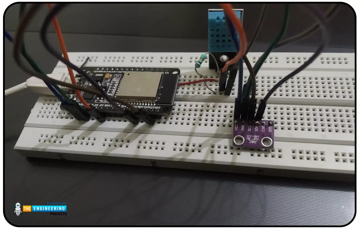
Hello readers, I hope you all are doing great. In this tutorial, we will learn how to interface the BMP280 sensor with the ES32 module to get temperature, pressure and altitude readings. Later, in this tutorial, we will also discuss how to upload these sensor readings to a web server.

Where To Buy?
No.ComponentsDistributorLink To Buy
1ESP32AmazonBuy Now

BMP280

BMP280 or Barometric pressure sensor is a module used to measure temperature pressure and altitude. The small size and low power consumption feature of this sensor makes it feasible for battery-powered devices, GPS modules and mobile applications etc.

Fig. 1 BMP280 Sensor

The BMP280 is the product of BOSCH which is based on Bosch’s proven Piezo-resistive pressure sensor technology featured with high accuracy, long term stability, linearity and high EMC robustness.

BMP280 is the successor of the BMP180 sensor and offers high performance in all the areas that require precise temperature and pressure measurements.

Emerging applications like fitness, indoor navigation, GPS refinement requires relative accuracy and BMP280 is perfect for such applications. Very low TCO (Temperature coefficient of Offset ) makes this module preferable over other available modules for temperature measurements.

We can also use a DHT11/DHT22 sensor for temperature and humidity measurements but the BMP280 sensor provides better accuracy (i.e., 0.01°C) than DHT sensors.

Technical specifications of BMP280

  • Operating voltage: 1.8 -3.3V DC
  • Communication protocols supported: SPI, I2C
  • Ultra low power consumption
  • Temperature accuracy: 1°C
  • Temperature range: -40 to 85°C
  • Absolute accuracy : 1 hPa

Components required:

  • ESP32 development board
  • Arduino IDE for programming
  • BMP280 sensor
  • Breadboard
  • Connecting wires

Interfacing BMP280 with ESP32

There are two methods of interfacing BMP280 sensor with ESP32 module:

  1. I2C protocol
  2. SPI protocol

In the bMP280 Sensor module, there are six interfacing pins including VCC and GND.

Fig. Interfacing BMP280 and ESP32

We are using the I2C protocol for interfacing the two (ESP and BMP280) so only SCL and SDA pins will be used with power pins for interfacing. The SDO and CSB pins will be used only if you are using the SPI protocol for interfacing.

Table 1

Programming with Arduino IDE

We are using Arduino IDE to compile and upload code into the ESP32 module. You must have ESP32 board manager installed on your Arduino IDE to program the ESP32 module. To know more about Arduino IDE and how to use it, follow our previous tutorial i.e., on ESP32 programming series. The link is given below:

https://www.theengineeringprojects.com/2021/11/introduction-to-esp32-programming-series.html

Steps to add the necessary libraries in Arduino IDE:

  • Go to Tools >> Manage Libraries.

Fig. 2 manage libraries

  • Search for the Adafruit BMP280 library in Library Manager and click Install.

Fig. 3 Install library

Getting I2C address

  • In order to interface your ESP32 with BMP280, you should know the I2C address of the sensor (BMP280).
  • To obtain the address of the I2C device, copy and paste the below attached code into your Arduino IDE.
  • Compile and upload the code.
  • Open the serial monitor at 115200 baud rate.
  • Now you should see the address of your I2C device printed on the serial monitor.
  • Copy the I2C address and paste in your final code (interfacing esp32 and BMP290 sensor).

#include <Wire.h>

void setup()

{

Wire.begin();

Serial.begin(115200);

Serial.println("\nI2C Scanner");

}

void loop()

{

byte error, address;

int nDevices;

Serial.println("Scanning...");

nDevices = 0;

for(address = 1; address < 127; address++ )

{

Wire.beginTransmission(address);

error = Wire.endTransmission();

if (error == 0)

{

Serial.print("I2C device found at address 0x");

if (address<16)

{

Serial.print("0");

}

Serial.println(address,HEX);

nDevices++;

}

else if (error==4)

{

Serial.print("Unknow error at address 0x");

if (address<16) {

Serial.print("0");

}

Serial.println(address,HEX);

}

}

if (nDevices == 0) {

Serial.println("No I2C devices found\n");

}

else {

Serial.println("done\n");

}

delay(5000);

}

Code (Interfacing and fetching sensor reading from BMP280 with ESP32)

#include <Wire.h>

#include <Adafruit_BMP280.h>

#define BMP_SDA 21

#define BMP_SCL 22

Adafruit_BMP280 bmp280;

void setup()

{

Serial.begin(115200);

Serial.println("Initializing BMP280");

boolean status = bmp280.begin(0x76);

if (!status)

{

Serial.println("Not connected");

}

}

void loop()

{

float temp = bmp280.readTemperature();

Serial.print("temperature: ");

Serial.print(temp);

Serial.println("*C");

float altitude = bmp280.readAltitude(1011.18);

Serial.print("Altitude: ");

Serial.print(altitude);

Serial.println("m");

float pressure = (bmp280.readPressure()/100);

Serial.print("Pressure: ");

Serial.print(pressure);

Serial.println("hPa");

Serial.println(" ");

delay(1000);

}

Code Description

  • The first task is adding necessary header files.
  • We are using two libraries:
    • The Wire.h is used to enable I2C communication/interfacing.
    • The second library we are using is, Adafruit_BMP280.h is to control the BMP sensor and access its respective function.

Fig. 4

  • As we mentioned earlier, we are using the I2C protocol for interfacing BMP280 with ESP32. So we need to define the I2C GPIO pins.
  • In the ESP32 DevKit V1 development board, the GPIO_21 and GPIO_22 are the SDA and SCL pins for I2C communication.
  • Then a bmp280 object is declared for interfacing the sensor.

Fig. 5

Setup()

  • In the setup() function, we are initializing the serial communication at 115200 baud rate for debugging purposes.
  • The BMP280 sensor is initialized with bmp280.begin() function where we are passing the I2C address of the module as an argument.
  • Next, we need to check the status of the interface and the respective result will be printed on the serial monitor.

Fig. 6

Loop()

  • The next task is getting the sensor readings.
  • Here we are measuring three parameters, temperature, humidity and altitude.
  • A float type variable “temp” is defined to store the temperature readings observed from BMP280 sensor using readTemperature() function.

Fig. 7

  • Next, the altitude is measured using bmp280.readAltitude function.
  • We need to adjust the altitude to the local forecast using the multiplying factor.

Fig. 8

  • The bmp280.readPressure() function is used to obtain the pressure using BMP280 sensor.
  • BMP280 sensor readings will be updated every time with a delay of 1 second.

Fig. 9

Testing

  • Open your Arduino IDE and paste the above code.
  • Compile and upload the code into ESP32 development board.
  • Before uploading the code make sure that you have selected the correct development board and COM port.

Fig. 10 Select development board and COM port

  • Once the code is uploaded successfully, open the Serial monitor and select the 1115200 baud rate (as per your code instructions).
  • Now you should see the readings obtained from barometric pressure sensor.

Fig. 11 Serial monitor output

Uploading BMP280 Sensor data to ThingSpeak server

Most of the industries and organizations these days are shifting to the efficient ways of operating things and the IoT internet of things is one of them.

Internet of Things is a system of multiple inter-related computing devices. The factor ‘thing’ in IoT is designated to an entity capable of communicating data over a network (IOT), which can be a digital machine, sensor, human being, animals etc.

Each component that is included in IoT network is assigned with an unique identity called UID and the ability to communicate data over IoT network without any external human or computer intervention.

Fig. 12 IoT

ThingSpeak is an open data platform for the Internet of Things applications. It is a MathWorks web service that allows users to send sensor readings and data to the cloud. We can also visualize and act on the data (calculate the data) that is sent to ThingSpeak by the devices. The information can be saved in both private and public channels.

ThingSpeak is frequently used for IoT prototyping and proof-of-concept devices that require data analysis.

Programming with Arduino IDE

Downloading and installing the required Library file:

  • Follow the link attached below to download the thingSpeak Arduino library:

https://github.com/mathworks/thingspeak-arduino

  • Open the Arduino IDE.
  • Go to Sketch >> Include Library >> Add .ZIP Library and select the downloaded zip file.

Fig. 13 Adding ThingSpeak library

To check whether the library is successfully added or not:

  • Go to Sketch >> Include Library >> Manage Libraries

Fig. 14

  • Type thingspeak in the search bar.

Fig, 15 Arduino IDE Library manager

  • The ThingSpeak library by MathWorks has been successfully downloaded.
 

Getting Started with ThingSpeak

  • To create and account or log in to ThingSpeak (operated by MathWorks) server follow the link: https://thingspeak.com/
  • Click on Get Started for free.

Fig. 16 Getting started for free

  • Enter the required details to create a MathWorks account as shown below:

Fig. 17 Create new account

  • If you have already created a MathWorks account, then click on Sign in.

Fig. 18 MathWorks Sign in

  • Create a channel by clicking on the New Channel

Fig. 19 New Channel

  • Enter the respective details in the channel.
  • Because we are measuring three parameters (temperature, pressure and altitude), hence we need to create three different fields in this channel.

Fig. 20 Creating channel and respective fields

  • Press “save” button.

Fig. 21 save the channel

  • After successfully saving the channel, a new window will open containing the channel details and Channel Stats.
  • In the same window, go to API Keys which contains the Write API keys and Read API keys.
  • Copy the Write API key and paste this in ESP32 Arduino code to upload the sensor readings on ThingSpeak server.
  • You can also customize the chart in Private View. Click on the icon present at the top right menu of Field Chart (in red box) to edit the chart.
  • Edit the details as per your requirements and click on save button to save the details.

Fig. 22 Field Chart Edit

  • Now your ThingSpeak channel is ready to communicate and save/store data.

Code (Arduino IDE)

// ------style guard ----

#ifdef __cplusplus

extern "C"

{

#endif

uint8_t temprature_sens_read();

#ifdef __cplusplus

}

#endif

uint8_t temprature_sens_read();

// ------header files----

#include <WiFi.h>

#include "ThingSpeak.h"

#include <Wire.h>

#include <Adafruit_BMP280.h>

#define BMP_SDA 21

#define BMP_SCL 22

Adafruit_BMP280 bmp280;

// -----netwrok credentials

const char* ssid = "public"; // your network SSID (name)

const char* password = "ESP32@123"; // your network password

WiFiClient client;

// -----ThingSpeak channel details

unsigned long myChannelNumber = 4;

const char * myWriteAPIKey = "9R3JZEVBG73YE8BY";

// ----- Timer variables

unsigned long lastTime = 0;

unsigned long timerDelay = 1000;


void setup()

{

Serial.begin(115200); // Initialize serial

Serial.println("Initializing BMP280");

boolean status = bmp280.begin(0x76);

if (!status)

{

Serial.println("Not connected");

}

//Initialize Wi-Fi

WiFi.begin(ssid, password);

Serial.print("Connecting to Wi-Fi");

while (WiFi.status() != WL_CONNECTED)

{

Serial.print(".");

delay(100);

}

Serial.println();

Serial.print("Connected with IP: ");

Serial.println(WiFi.localIP());

Serial.println();

// Initialize ThingSpeak

ThingSpeak.begin(client);

}

void loop()

{

if ((millis() - lastTime) > timerDelay )

{

float temp = bmp280.readTemperature(); //temperature measurement

Serial.print("temperature: ");

Serial.print(temp);

Serial.println("*C");

float altitude = bmp280.readAltitude(1011.18); //altitude measurement

Serial.print("Altitude: ");

Serial.print(altitude);

Serial.println("m");

float pressure = (bmp280.readPressure()/100); //pressure measurement

Serial.print("Pressure: ");

Serial.print(pressure);

Serial.println("hPa");

Serial.println(" ");

ThingSpeak.setField(1, temp );

ThingSpeak.setField(2, altitude);

ThingSpeak.setField(3, pressure);

// Write to ThingSpeak. There are up to 8 fields in a channel, allowing you to store up to 8 different

// pieces of information in a channel. Here, we write to field 1.

int x = ThingSpeak.writeFields(myChannelNumber,

myWriteAPIKey );

if(x == 200)

{

Serial.println("Channel update successful." );

}

else

{

Serial.println("Problem updating channel. HTTP error code " + String(x) );

}

lastTime = millis();

}

}

Code Description

We are describing only the ThingSpeak server part as the BMP280 and ESP32 interfacing part has already been discussed in the above code description.

  • The style guard is used at the beginning to declare some function to be of “C” linkage, instead of “C++”
  • Basically, it allows the C++ code to interface with C code.

Fig. 23 Style guard

  • Add the necessary header/library files.
  • We have already discussed above how to download and add the ThingSpeak library file to Arduino IDE.

Fig. 24 Libraries

  • Enter the network credentials (SSID and Password).

Fig. 25

  • A Wi-Fi client is created to connect with ThingSpeak.

Fig. 26

  • Define timer variables.

Fig. 27

  • Add the channel number and API (Write) Key. If you have created only one channel then the channel number will be ‘1’.

Fig. 28

Setup()

    • Initialize the Serial monitor with a 115200 baud rate for debugging purposes.

Fig. 29

  • Set ESP32 Wi-Fi module in station mode using mode() function.
  • Enable ESP32’s Wi-Fi module using begin() function which is using SSID and password as arguments.
  • Wait until the ESP32 is not connected with the wifi network.

Fig. 30

  • Initialize the ThingSpeak server using begin() function that is passing client (globally created) as an argument.

Fig. 31


Loop()

  • We are defining three float type variables to save temperature, altitude and pressure measurements respectively.

Fig. 32 Sensor readings

  • Setting up the ThingSpeak fields for respective sensor measurement. The various sensor readings are passed as arguments inside the ThingSpeak.setField() function with there respective filed number.

Fig. 33 setting respective Fields

  • writeFields() function is used to write data to the ThingSpeak server. This function is using the channel number and API key as an argument.

Fig. 34

  • Return the code 200 if the sensor readings are successfully published to ThingSpeak server and print the respective results on the serial monitor.

Fig. 35

Results

  • Open your Arduino IDE and paste the above code.
  • Compile and upload the code into the ESP32 development board.
  • Before uploading the code make sure that you have selected the correct development board and COM port.
  • Make sure the Wi-Fi network to which your ESP device is supposed to connect is active.
  • Open the serial monitor at a 115200 baud rate and press the EN button from ESP32 development.
  • Once your ESP32 is connected with the wi-fi network, open the channel you have created on the ThingSpeak server.
  • Now you see the sensor readings displayed on their respective fields.

Fig. 36 ThingSpeak server

  • You can also compare the data displayed on the server with the serial monitor.

Fig. 37 Sensor readings on the Serial monitor

This concludes the tutorial. I hope you found this of some help and also hope to see you soon with a new tutorial on ESP32.

Update LCD Display with ESP32 Web Server

Hello readers, I hope you all are doing great.

ESP32 is a powerful chip for Internet of Things applications. This tutorial is also based on one of the ESP32 applications in the field of IoT.

Where To Buy?
No.ComponentsDistributorLink To Buy
1ESP32AmazonBuy Now

Project Overview

In this tutorial, we will learn how to update LCD display with new data or input using a web server created with ESP32.

Fig. 1

To achieve the target, we will be using an HTML (Hypertext Markup Language) form to provide web input and then update the text displayed on LCD. The values or input received from the webserver will be further stored inside a variable in the code for further use (to display on LCD).

We have already posted a tutorial on LCD (Liquid Crystal Display) interfacing with ESP32. In that tutorial, we demonstrated how to display the hard-coded data (in the ESP32 module) on LCD.

ESP32 Web Server

A web server is computer software and hardware that accepts requests and responds to those requests using HTTP (Hypertext transfer protocol) or HTTPS (HTTP Secure) (HTTP is a network protocol for delivering online content to client user agents).

The ESP32 standalone web server is mobile-enabled and can be accessed from any device with a browser on the local network. B. Mobile phones, computers, laptops, tablets. However, all the devices must be connected to the same WiFi network to which the ESP32 is connected.

Software and Hardware requirements

  • ESP32 development board
  • 16*2 LCD display
  • 10K trim-pot
  • Breadboard or general-purpose PCB
  • Connecting Wires
  • Arduino IDE
  • h, ESPAsynchWenServer.h header files

Interfacing16*2 LCD with ESP32

There are basically two ways to connect the ESP32 to a 16 * 2 LCD display.

  1. Interface with I2C adapter
  2. Direct connection without using I2C adapter.

Connecting an LCD display without an I2C adapter is cheap, but this method requires more connection cables and is complicated to implement. On the other hand, using an I2C adapter reduces complexity but increases cost. In this tutorial, you will connect the ESP32 directly without using an I2C adapter.

Table: 1

Fig. 2: ESP32 and 16*2 LCD interfacing

For more details on interfacing 16*2 LCD with ESP32, follow our previous tutorial at www.theengineeringprojects.com

Programming ESP32

Installing ESP32 board manager in Arduino IDE:

We are using Arduino IDE to compile and upload code into ESP32 module. You must have ESP32 board manager installed on your Arduino IDE to program ESP32 module. To know more about Arduino IDE and how to use it, follow our previous tutorial i.e., on ESP32 programming series. The link is given below:

https://www.theengineeringprojects.com/2021/11/introduction-to-esp32-programming-series.html

Installing necessary libraries:

ESP32 board manager doesn’t come with inbuilt libraries to create an asynchronous web server. So we need to download the library file from external sources and then add into Arduino IDE.

We need to install two library files:

  1. ESPAsynWebServer: Follow the link https://github.com/me-no-dev/ESPAsyncWebServer to download the respective library.
  1. AsyncTCP: You can download the AsyncTCP library from the following link https://github.com/me-no-dev/AsyncTCP

Once you have successfully downloaded the required libraries, next step it to install or add these libraries in Arduino IDE.

To add the libraries in Arduino IDE, go to Sketch >> Include Library >> Add .zip library and then select the downloaded library files.

Fig. 3: adding necessary libraries

Arduino IDE code

#include < WiFi.h >

#include < AsyncTCP.h >

#include < ESPAsyncWebServer.h >

#include < LiquidCrystal.h > // LCD header file

LiquidCrystal lcd (22, 23, 5, 18, 19, 21 );

AsyncWebServer server ( 80 );

// Enter your netwrok credentials

const char* ssid = "replace this with netwrok SSID";

const char* password = "replace this with Password";

const char* PARAM_INPUT_1 = "data_field1";

const char* PARAM_INPUT_2 = "data_field2";

// HTML web page to handle data input fields

const char index_html[] PROGMEM = R"rawliteral(

<!DOCTYPE HTML> <html> <head>

<title> ESP Input Form </title>

<meta name = " viewport" content="width=device-width, initial-scale=1 ">

<style>

html{ font-family: Times New Roman; display: inline-block; text-align: justify;}

</style>

</head> <body>

<form action="/get">

Data_field1: <input type="text" name="data_field1" >

<input type="submit" value="Post ">

</form> <br>

<form action="/get">

Data_field2: <input type="text" name="data_field2">

<input type="submit" value="Post">

</form><br>

</body></html>)rawliteral";

void notFound(AsyncWebServerRequest *request) {

request->send(404, "text/plain", "Not found");

}

void setup() {


Serial.begin(115200);

WiFi.mode(WIFI_STA);

WiFi.begin(ssid, password);

if (WiFi.waitForConnectResult() != WL_CONNECTED) {

Serial.println("WiFi Failed!");

return;

}

Serial.println();

Serial.print("IP Address: ");

Serial.println(WiFi.localIP());

//===set LCD

lcd.begin(16, 2);

lcd.clear();

lcd.setCursor(1,0);

server.onNotFound(notFound);

server.begin();

// Send web page with input fields to client

server.on("/", HTTP_GET, [](AsyncWebServerRequest *request)

{

request->send_P(200, "text/html", index_html);

});

server.on("/get", HTTP_GET, [] (AsyncWebServerRequest *request) {

String inputMessage;

String inputParam;

// GET input1 value

if (request->hasParam(PARAM_INPUT_1))

{

inputMessage = request->getParam(PARAM_INPUT_1)->value();

inputParam = PARAM_INPUT_1;

}

// GET input2 value

else if (request->hasParam(PARAM_INPUT_2))

{

inputMessage = request->getParam(PARAM_INPUT_2)->value();

inputParam = PARAM_INPUT_2;

}

else

{

inputMessage = " No message sent";

inputParam = " none";

}

Serial.println ( inputMessage );

delay( 1000);

lcd.clear();

lcd.print( inputMessage);

request-> send (200, "text/html", " HTTP GET request sent to ESP32("

+ inputParam + "): " + inputMessage +

"<br><a href=\"/\"> Back to Home Page </a>");

});

}

void loop( )

{

}

Code Description

  • The first step is adding the necessary header files.
  • Here we are using two libraries:
    • The first one is WiFi.h, which is used to enable the Wi-Fi module and hence wireless network connectivity.
    • LiquidCrystal.h is used to call the necessary functions required to interface and control LCD with ESP32.
    • ESPAsynchWenServer library file is responsible for creating an asynchronous web server.
    • AsyncTCP is used to enable a multi-connection network for ESP32 (Espressif’s) microcontroller unit.

Fig. 4: Adding header files

  • Define the data and control pins (of 16*2 LCD) to be interfaced with ESP32.

Fig. 5: LCD data and control pins

  • While creating a web server we also need to assign a port and usually port 80 is used for local web server.

Fig. 6: server port

  • Enter the network credentials in place of SSID and PASSWORD.

Fig. 7: Enter Network credentials

  • The next thing is the declaration of variables for input data fields.

Fig. 8

Creating HTML Form

  • !DOCTYPE html><html> is used to describe/indicate that we are transmitting HTML, this command should always be the first thing we send.
  • <title> tag is used to write a title for the web page.
  • The next line in the code is used to make the web page responsive in any web browser.
  • The <style> tag is used to style the webpage, which includes the type of font, alignment, display etc.

Fig. 9: HTML web page

  • Next comes the HTML form for user input. We are going to create two data input fields for user input and each filed is having a Post button to send the new data string to the ESP device and the variable declared to store the input will be updated.
  • <form> tag is used to create the HTML form. Here we are creating an HTML form with two input fields namely the Data_field2 and Data_filed2 and each field is having individual Post buttons to post the input from the web server to the client.
  • The action attribute is used to specify, where to send the data input provided in the input data fields after pressing the post
  • After pressing the post button a new web page will open, indicating the status whether the input string is successfully posted or not.

Fig. 10: HTML form for data input

  • The two attributes, type and value specifies a button and the text on the button respectively.

Fig. 11: Post button.

  • If we make an invalid request, the notFound() function will be called.
 

Setup

  • Initialize the serial monitor at 115200 baud rate for debugging purpose.
    • begin() function is used to initialize the Wi-Fi module with Wi-Fi credentials used as arguments.
    • The While loop will continuously run until the ESP32 is connected to Wi-Fi network.

Fig. 12

  • If the device is connected to local Wi-Fi network then print the details on serial monitor.
  • localIP() function is used to fetch the IP address.
  • Print the IP address on serial monitor using println() function.

Fig. 13: Fetch/obtain the IP adrress

  • Initialize the 16*2 LCD using begin() function.
  • Clear the previous data from the LCD before printing or displaying the new one using clear() function.
  • Set the cursor position at row 1 and column 0 using setCursor() function.

Fig. 14: Set 16*2 LCD

  • begin() function is used to initialize the web server once ESP32 is connected with the Wi-Fi network.

Fig. 15: Initialize the server

Handling HTTP GET requests

  • The next part in the programming includes handling of HTTP GET requests.
  • When we access the route URL, we send the web page to client along with the data input fields.
  • We have defined a variable namely index_html to save the HTML text.

Fig. 16: Send web page to client

  • Next task is handling what happens when device receive a request on the /get routes.
  • To save input values, we have created two variables: inputPram and

Fig. 17

  • Next we need to check if HTTP get request contains the Data_input1 and Data_input1 These fields values are saved on PRAM_INPUT_1 and PRAM_INPUT2.
  • If the HTTP GET request contains inputs, then the inputMessage1 will be set to the value inserted in the data_field1.

Fig. read the input from HTML form

  • Else there will be no input for inputMessage.

Fig. 18

  • Print the input value saved on variable inputMessage using Serial.print command.
  • clear() command is used to clear the previous data printed on LCD.
  • New data or message received from the web server will be printed on the LCD display using print() function.

Fig. 19

  • After pressing the post button a new web page will open, indicating the status whether the input string is successfully posted or not.

Fig. 20

Testing

  • Open your Arduino IDE and paste the above code.
  • Change the network credentials, that is the SSID and PASSWORD as per you network setup.
  • Compile and upload the code into ESP32 development board.
  • Before uploading the code make sure that you have selected the correct development board and COM port.

Fig. 21: Select development board and COM port

  • Once the code is uploaded successfully, open the Serial monitor and select the 1115200 baud rate (as per your code instructions).
  • Make sure Wi-Fi to which your ESP device is supposed to connect is ON.
  • Once your ESP32 is connected to the internet, the IP address of the device will be printed on the Serial monitor.
  • Copy the IP address.
  • Open the browser and paste the IP address and press
  • A web page with HTML form containing two input fields will open as shown below:

Fig. 22: web Page

  • Enter the text in the HTML form you want to be printed on on the LCD display.
  • Press the Post

Fig. 23: Enter the Input to ESP32

  • After pressing the post button a new web page will open, indicating the status whether the input string is successfully posted or not.

Fig. 24: Input Updated

Fig. 25: IP address and Web Input on serial monitor.

Fig. 26: String input received from Web server, printed on LCD

This concludes the tutorial. We hope you found this of some help and also hope to see you soon with a new tutorial on ESP32.

Server-Sent Events with ESP32 and DHT11

Hello readers, I hope you all are doing great. In this tutorial, we will learn how to update a webpage using Server-Sent Events and the ESP32 web server.

Where To Buy?
No.ComponentsDistributorLink To Buy
1ESP32AmazonBuy Now

What is Server-Sent Events (SSE)?

It is a server push technology that enables the client devices to receive automatic updates from a server over HTTP (Hypertext Transfer Protocol) connection. SSE also describes how the server can initiate data transmission towards the client once an initial connection with the client has been established.

We have already posted a tutorial on how to implement Web socket protocol with ESP32 which is also a protocol used to notify events to a web client. Both the Server-Sent Events (SSE) and Web-Socket technologies seem to be quite similar but they are not.

The major difference between the two is that SSE is unidirectional, where the web client can only receive the updates from the ESP32 but it can’t send updates back to ESP32. On the other hand, the Web-socket protocol is bi-directional where both the web client and ESP32 can send and receive updates/events.

Fig. 1 Server-Sent event

How does the Server-Sent Event works?

The Server-Sent Event process initiates with an HTTP request from the web client or web page to the ESP32 web server. After that, the ESP32 is ready to send updates or events to the web client as they happen. But the web client can’t send any response or data to the ESP32 server after the initial handshake takes place.

Server-sent event technology can be used to communicate an event, GPIO states or to send sensor readings to the web client, whenever a new reading is observed.

Project Overview

For demonstration purpose, we are using a DHT11 sensor with the ESP32 module. ESP32 web server will display two things i.e., temperature and humidity observed using the DHT11 sensor. So, whenever a new reading is being observed, the ESP32 sends the reading to the Web Client over Server-sent events. After receiving the latest sensor reading the client updates the web page data.

Software and Hardware requirements

  • ESP32 development board
  • DHT11 sensor
  • Connecting Wires
  • Breadboard
  • Arduino IDE
  • Necessary Libraries

DHT11 (a Temperature and Humidity sensor)

Fig. 2 DHT11 sensor

DHT11 is a humidity and temperature sensor that measures its surrounding environment. It measures the temperature and humidity in a given area. It is made up of an NTC (negative temperature co-efficient) temperature sensor and a resistive humidity sensor. It also has an 8-bit microcontroller. The microcontroller is in charge of ADC (analog to digital conversion) and provides a digital output over the single wire protocol.

The DHT11 sensor can measure humidity from 20% to 90% with +-5 percent accuracy (RH or relative humidity) and temperature from 0 degrees Celsius to 50 degrees Celsius with +-2C accuracy.

DHT11 sensors can also be used to build a wired sensor network with a cable length of up to 20 meters.

Interfacing DHT11 with ESP32 module

Table 1

Note: Connect a 10K resistor between data and power (+5V) pin of DHT11 sensor module.

Fig. 3 ESP32 and DHT11 connections/wiring

Programming with Arduino IDE

We are using Arduino IDE to compile and upload code into the ESP32 module. You must have ESP32 board manager installed on your Arduino IDE to program the ESP32 module. To know more about Arduino IDE and how to use it, follow our previous tutorial i.e., on ESP32 programming series. The link is given below:

https://www.theengineeringprojects.com/2021/11/introduction-to-esp32-programming-series.html

Steps to add the necessary libraries in Arduino IDE:

  • Go to Tools >> Manage Libraries.

Fig. 4 manage libraries

  • Search for the necessary library in Library Manager and click Install.
  • We are attaching an image, where we are installing the DHT11 sensor library.

Fig. 5 Install DHT sensor library

  • Follow the similar procedure for rest of the libraries.
  • After successfully installing all the required libraries close the Library Manager tab.

ESP32 board manager doesn’t come with inbuilt libraries to create an asynchronous web server. So we need to download the library file from external sources and then add into Arduino IDE.

We need to install two library files:

  1. ESPAsynWebServer: Follow the link https://github.com/me-no-dev/ESPAsyncWebServer to download the respective library.
  1. AsyncTCP: You can download the AsyncTCP library from the following link https://github.com/me-no-dev/AsyncTCP

Once you have successfully downloaded the required libraries, next step it to install or add these libraries in Arduino IDE.

To add the libraries in Arduino IDE, go to Sketch >> Include Library >> Add .zip library and then select the downloaded library files.

Fig. 6 adding necessary libraries

Arduino Code

#include <WiFi.h>

#include <AsyncTCP.h>

#include <ESPAsyncWebServer.h>

#include "DHT.h"

#define DHTPIN 4 // Digital pin connected to the DHT sensor

#define DHTTYPE DHT11 // DHT 11

// Initializing the DHT11 sensor.

DHT dht(DHTPIN, DHTTYPE);

// Replace with your network credentials

const char* ssid = "SSID";

const char* password = "password";

// Create AsyncWebServer object on port 80

AsyncWebServer server(80);

// Create an Event Source on /events

AsyncEventSource events("/events");

// Timer variables

unsigned long lastTime = 0;

unsigned long timerDelay = 20000; //20 sec timer delay

//==== Creating web page

const char index_html[] PROGMEM = R"rawliteral(

<!DOCTYPE HTML><html>

<head>

<title>SSE with ESP32 Web Server</title>

<meta name="viewport" content="width=device-width, initial-scale=1">

<link rel="stylesheet" href="https://use.fontawesome.com/releases/v5.7.2/css/all.css" integrity="sha384-fnmOCqbTlWIlj8LyTjo7mOUStjsKC4pOpQbqyi7RrhN7udi9RwhKkMHpvLbHG9Sr" crossorigin="anonymous">

<link rel="icon" href="data:,">

<style>

html {font-family: Times New Roman; display: inline-block; text-align: justify;}

p { font-size: 1.2rem;}

body { margin: 0;}

.topnav { overflow: hidden; background-color: blue; color: white; font-size: 1rem; }

.content { padding: 20px; }

.card { background-color: #ADD8E6; box-shadow: 2px 2px 12px 1px rgba(140,140,140,.5); }

.cards { max-width: 600px; margin: 0 auto; display: grid; grid-gap: 2rem; grid-template-columns: repeat(auto-fit, minmax(200px, 1fr)); }

.reading { font-size: 1.4rem; }

</style>

</head>

<body>

<div class="topnav">

<h1>Server-Sent Events </h1>

<h2> DHT11 Sensor Data </h2>

</div>

<div class="content">

<div class="cards">

<div class="card">

<p> DHT11 Temperature</p><p><span class="reading"><span id="temp">%TEMPERATURE%</span> &deg;C</span></p>

</div>

<div class="card">

<p> DHT11 Humidity</p><p><span class="reading"><span id="hum">%HUMIDITY%</span> &percnt;</span></p>

</div>

</div>

</div>

<script>

if (!!window.EventSource)

{

var source = new EventSource('/events');

source.addEventListener('open', function(e)

{

console.log("Events Connected");

}, false);

source.addEventListener('error', function(e)

{

if (e.target.readyState != EventSource.OPEN)

{

console.log("Events Disconnected");

}

}, false);

source.addEventListener('message', function(e)

{

console.log("message", e.data);

}, false);

source.addEventListener('temperature', function(e)

{

console.log("temperature", e.data);

document.getElementById("temp").innerHTML = e.data;

}, false);

source.addEventListener('humidity', function(e)

{

console.log("humidity", e.data);

document.getElementById("hum").innerHTML = e.data;

}, false);

}

</script>

</body>

</html>)rawliteral";


void setup() {

Serial.begin(115200); //initialize serial monitor

//===set and initialize Wi-Fi

WiFi.mode(WIFI_STA);

WiFi.begin(ssid, password);

Serial.print("Connecting to WiFi ..");

while (WiFi.status() != WL_CONNECTED)

{

Serial.print('.');

delay(1000);

}

Serial.print("IP Address: ");

Serial.println(WiFi.localIP()); // print the IP address

//====Initialize DHT11 sensor

dht.begin();

//====Handle Web Server

server.on("/", HTTP_GET, [](AsyncWebServerRequest *request){

request->send_P(200, "text/html", index_html);

});

// Handle Web Server Events

events.onConnect([](AsyncEventSourceClient *client)

{

if(client->lastId())

{

Serial.printf("Client reconnected! Last message ID that it got is: %u\n",

client->lastId());

}

// send event with message "hello!", id current millis

// and set reconnect delay to 1 second

client->send("hello!", NULL, millis(), 10000);

});

server.addHandler(&events);

server.begin();

}

void loop()

{

delay(2000);

float humidity = dht.readHumidity();

// Read temperature as Celsius (the default)

float temperature = dht.readTemperature();

// Check if any reads failed and exit early (to try again).

if (isnan(humidity) || isnan(temperature))

{

Serial.println(F("Failed to read from DHT sensor!"));

return;

}

if ((millis() - lastTime) > timerDelay)

{

// Send Events to the Web Server with the Sensor Readings

events.send("ping",NULL,millis());

events.send(String(temperature).c_str(),"temperature",millis());

events.send(String(humidity).c_str(),"humidity",millis());

Serial.print(F("Humidity(%): "));

Serial.println(humidity);

Serial.print(F("Temp.: "));

Serial.print(temperature);

Serial.println(F("°C "));

}

}

Code Description

  • Here we are using four libraries:
    • The first one is WiFi.h, which is used to enable the Wi-Fi module and hence wireless network connectivity.
    • DHT.h is used to call the necessary functions required to interface DHT sensor with ESP32.
    • ESPAsynchWenServer library file is responsible for creating an asynchronous web server.
    • AsyncTCP is used to enable multi-connection network for ESP32 (Espressif’s) microcontroller unit.

Fig. 7 Header files

  • Next step is the declaration of variables for DHT11 sensor.
  • We are declaring 2 variables, the first one is the DHTPIN to store the GPIO number receiving input from DHT11 sensor and another variables is to define the type of DHT (i.e., whether DHT11 or DHT22).

Fig. 8 Global declarations

  • Next we are creating a DHT object called dht in the DHT sensor type (defined earlier) and the DHT pin.

Fig. 9

  • Enter the network credentials in place of SSID and PASSWORD.

Fig. 10 Enter Network credentials

  • While creating a web server we also need to assign a port and usually port 80 is used for local web server.

Fig. 11 Server port

  • Next step is creating a new event source(on /events).

Fig. 12 Event source

  • Timer variable declaration: the timerDelay and lastTime variables are declared to add delay using timer, instead of using delay() function. Here we are adding a delay of 20 seconds which means the web browser will be updated with new sensor reading in every 20 sec.

Fig. 13 Timer Variables

Creating the Web Page

  • !DOCTYPE html><html> is used to describe/indicate that we are transmitting HTML, this command should always be the first thing we send.
  • <title> tag is used to write title for the web page.

Fig. 14

  • The <style> tag is used to style the webpage, which includes the type of font, alignment, display, color, dimensions etc. You can make changes in the <style> tag as per your requirements.

Fig. 15

  • The content, which is to be displayed on the Web page is written inside the <body> tag. The <body> tag includes two headings h1 and h2 and sensor readings (temperature and humidity).

Fig. 16

Initializing an Event-Source connection

  • JavaScript is written inside the inside the <script> tag, which is responsible for initializing an event source connection with the web server and also to handle the events received from the web server.
  • An object EventSource is created and along with that the URL of the webpage sending the updates is also specified.
  • addEventListener() function is used to listen to the messages coming from the web server, once the event source is initiated successfully.

Fig. 17

  • Next task is adding an event listener for Whenever a new temperature reading is observed from the DHT11 sensor, ESP32 sends a “temperature” event to the web client.

Fig. 18

  • Similarly, another event is generated for It prints the latest readings on the web browser & puts the received data into the element with respective ID on the webpage.

Fig. 19

Setup

  • Initialize the serial monitor at a 115200 baud rate for debugging purposes.
    • begin() function is used to initialize the Wi-Fi module with Wi-Fi credentials used as arguments.
    • The While loop will continuously run until the ESP32 is connected to the Wi-Fi network.

Fig. 20

  • If the device is connected to a local Wi-Fi network then print the details on the serial monitor.
  • localIP() function is used to fetch the IP address.
  • Print the IP address on the serial monitor using println() function.

Fig. 21 Fetch/obtain the IP address


Fig. 22 Initialize DHT sensor

Handling HTTP GET requests

  • The next part in the programming includes handling HTTP GET requests.
  • When we access the route URL, we send the web page to the client along with the data input fields.
  • We have defined a variable namely index_html to save the HTML text.

Fig. 23

Handling Server Event source

  • The next task is setting up the event source on the webserver.

Fig. 24 Handling server events


Initializing web server

  • Initialize the webserver using begin() function.

Fig. 24 initializing web server


Loop()

  • DHT11 is a very slow sensor. It takes almost 250ms to read temperature and humidity.
  • So it is preferred to wait a few seconds before a new measurement or updated sensor reading.
  • Next, we are defining a float type variable ‘h’ to store humidity measured from the DHT11 sensor.
  • readHumidity() function is used to observe the humidity value.
  • readTemperature() function is used to read the surrounding temperature with the DHT11 sensor.

Fig. 25

 
  • If somehow the sensor fails to read or observer temperature and humidity values, then the respective results will be printed on the serial monitor.

Fig. 26 If error occurs while reading data from DHT11

Sending Events to the server

  • Send the updated events or the latest observation from the DHT11 sensor the web browser over the local network.
  • The sensor readings will be updated in every 20 second as per the code instructions.

Fig. 27 Sending events to the server

  • Print the temperature and humidity readings (observer form the DHT11 sensor) on the Serial monitor.

Fig. 28 Print Sensor data on the Serial monitor

Testing

  • Open your Arduino IDE and paste the above code.
  • Change the network credentials, that is the SSID and PASSWORD as per you network setup.
  • Compile and upload the code into ESP32 development board.
  • Before uploading the code make sure that you have selected the correct development board and COM port.

Fig. 29 Select development board and COM port

  • Once the code is uploaded successfully, open the Serial monitor and select the 1115200 baud rate (as per your code instructions).
  • Make sure Wi-Fi to which your ESP device is supposed to connect is ON.
  • Once your ESP32 is connected to the internet, the IP address of the device will be printed on the Serial monitor.
  • Copy the IP address.
  • Open the browser and paste the IP address and press
  • A web page will appear, as shown below:

Fig. 30

  • The web page will be updated with new data every 20 seconds, as per the code instructions and we do not even need to refresh the web page for latest event updates due to SSE technology.

Fig. 31

This concludes the tutorial. I hope you found this of some help and also hope to see you soon with a new tutorial on ESP32.

ESP32 DHT11 Interfacing with ThingSpeak WebServer

ESP32 module comes with multiple inbuilt features and peripheral interfacing capability is one of those features. ESP32 module also consists of an inbuilt temperature sensor, but that can only measure the temperature of the ESP32 core not the temperature of the surrounding environment. So it is required to use a peripheral sensor to measure the temperature of the surrounding environment like home, garden, office etc.

Hello readers. I hope you all are doing great. In this tutorial, we will learn how to interface DHT11 (temperature and humidity sensor) with the ESP32. Later in this tutorial, we will discuss how to share the sensor readings obtained from the DHT11 sensor to a web server.

Before moving towards the interfacing and programming part, let’s have a short introduction to the DHT11 sensor, its working and its connections.

Where To Buy?
No.ComponentsDistributorLink To Buy
1ESP32AmazonBuy Now

DHT11 (A Temperature and Humidity Sensor)

Fig. 1: DHT11 sensor

DHT11 is used to measure humidity and temperature from its surrounding. It monitors the ambient temperature and humidity of a given area. It consists of an NTC (negative temperature co-efficient) temperature sensor and a resistive type humidity sensor. It also consists of an 8-bit microcontroller. The microcontroller is responsible for performing ADC (analog to digital conversion) and provides a digital output over the single wire protocol.

DHT11 sensor can measure humidity from 20% to 90% with +-5% (RH or relative humidity) of accuracy and can measure the temperature in the range of 0 degrees Celsius to 50 degrees Celsius with +-2C of accuracy.

DHT11 sensors can also be used to implement a wired sensor system using a cable length of up to 20 meters.

There are two DHT modules (DHT11 and DHT22) available in the market to measure temperature and humidity. The purpose of both module are same but with different specifications. Like DHT22 sensor provides broader temperature and humidity sensitivity ranges. But DHT22 is costlier than DHT11. So you can prefer to use any of the module, as per your requirements.

Components required

  • ESP32 development board
  • DHT11 sensor
  • 10K resistor
  • Connecting wires
  • Breadboard

Interfacing DHT11 with ESP32 module

Table: 1

Note: Connect a 10K resistor between data and power (+5V) pin of DHT11 sensor module.

Fig. 2: ESP32 and DHT11 connections/wiring

Arduino Programming

We are using Arduino IDE to compile and upload code into ESP32 module. To know more about Arduino IDE and how to use it, follow our previous tutorial i.e., on ESP32 programming series. Link is given below:

https://www.theengineeringprojects.com/2021/11/introduction-to-esp32-programming-series.html

Adding required libraries in Arduino IDE

DHT11 sensor uses single wire protocol to communicate data which requires a precise timing. In order to interface DHT11 sensor with ESP32 module it is required to add necessary libraries. To install the DHT11 sensor library;

  • Go to Tools >> Manage Libraries.

Fig. 3: manage libraries

 
  • Type DHT in the search bar and install the DHT sensor library as shown below.

Fig. 4: Install DHT sensor library


Arduino IDE code to interface DHT11 with ESP32

#include "DHT.h"

#define DHTPIN 4 // Digital pin connected to the DHT sensor

#define DHTTYPE DHT11 // DHT 11

// Initializing the DHT11 sensor.

DHT dht(DHTPIN, DHTTYPE);

void setup() {

Serial.begin(115200);

Serial.println(F("DHT test string!"));

dht.begin();

}


void loop() {

// Wait a few seconds between measurements.

delay(2000);

// Reading temperature or humidity takes about 250 milliseconds!

// Sensor readings may also be up to 2 seconds 'old' (its a very slow sensor)

float h = dht.readHumidity();

// Read temperature as Celsius (the default)

float t = dht.readTemperature();

// Read temperature as Fahrenheit (isFahrenheit = true)

float f = dht.readTemperature(true);

// Check if any reads failed and exit early (to try again).

if (isnan(h) || isnan(t) || isnan(f)) {

Serial.println(F("Failed to read from DHT sensor!"));

return;

}

// Compute heat index in Fahrenheit (the default)

float hif = dht.computeHeatIndex(f, h);

// Compute heat index in Celsius (isFahreheit = false)

float hic = dht.computeHeatIndex(t, h, false);

Serial.print(F("Humidity(%): "));

Serial.println(h);

Serial.print(F("Temp.: "));

Serial.print(t);

Serial.println(F("°C "));

Serial.print(F("Temp.: "));

Serial.print(f);

Serial.println(F("°F "));

Serial.print(F("Heat index: "));

Serial.println(hic);

Serial.println(" ");

Serial.print(F("°C "));

Serial.print(hif);

Serial.println(F("°F"));

}

Code Description

  • Add the necessary header files required to interface the DHT11 sensor.

Fig. 5: Add necessary libraries

  • The next step is the declaration of variables for the DHT11 sensor.
  • We are declaring 2 variables, the first one is the DHTPIN to store the GPIO number receiving input from the DHT11 sensor and another variable is to define the type of DHT (i.e., whether DHT11 or DHT22).

Fig. 6: Global declarations

  • Next, we are creating a DHT object called dht in the DHT sensor type (defined earlier) and the DHT pin.

Fig. 7


Setup()

  • Inside the setup function, the first task is initializing the serial monitor at a 115200 baud rate for debugging purposes.
  • Initialize the DHT sensor using begin() function.

Fig. 8

Loop()

  • DHT11 is a very slow sensor. It takes almost 250ms to read temperature and humidity.
  • So it is preferred to wait a few seconds before a new measurement or updated sensor reading.
  • Next, we are defining a float type variable ‘h’ to store humidity measured from the DHT11 sensor.
  • readHumidity() function is used to observe the humidity value.

Fig. 9

  • readTemperature() function is used to read the surrounding temperature with DHT11 sensor.

Fig. 10

  • If somehow the sensor fails to read or observer temperature and humidity values, then the respective results will be printed on the serial monitor.

Fig. 11

  • Another float type variable hif is defined to store the heat index value.
  • computeHeatIndex() function is used to calculate the heat index value.

Fig. 12: Heat index

Results

  • Open the Arduino IDE and paste the above code.
  • Compile and upload the program after selecting the correct development board and COM port.
  • Connect the DHT11 sensor with ESP32 board as per the given circuit instructions.

Fig. ESP32 and DHT11 interfacing

  • Open the serial monitor at 115200 baud rate and press the enable (EN) button from the ESP32 development board.
  • You should see the temperature, humidity, Heat index readings printed on the serial monitor.

Fig. 13: Readings observed from DHT11 sensor

Uploading DHT11 sensor reading to ThingSpeak Server

The IoT is the interconnection of physical objects or devices with sensors and software accessing capabilities to communicate data or information over the internet.

To build an IoT network, we need an interface medium that can fetch, control, and communicate data between sender and receiver electronics devices or servers.

Espressif Systems created the ESP32 Wi-Fi chip series. The ESP32 module is equipped with a 32-bit Tensilica microcontroller, 2.4GHz Wi-Fi connectivity, an antenna, memory, and power management modules, and much more. All of these built-in features of this ESP32 module make it ideal for IoT applications.

ThingSpeak web servie

It is an open data platform for the Internet of Things (Internet of Things). ThingSpeak is a MathWorks web service that allows us to send sensor readings/data to the cloud. We can also visualise and act on the data (calculate the data) sent to ThingSpeak by the devices. Data can be stored in both private and public channels.

ThingSpeak is commonly used for internet of things prototyping and proof of concept systems requiring analytics.


Getting Started with ThingSpeak

  • To create and account or log in to ThingSpeak (operated by MathWorks) server follow the link: https://thingspeak.com/
  • Click on Get Started for free.

Fig. 14: Getting started for free

  • Enter your details to create a MathWorks account as shown below:

Fig. 15: Create new account

  • If you have already created a MathWorks account, then click on Sign in.

Fig. 16: MathWorks Sign in

  • Create a channel on MathWorks server by clicking on the New Channel
  • ThingSpeak web service allows its user to create and save maximum of 4 channels for free.
  • If you are want access to more channels then you need to make payment for that.

Fig. 17: New Channel

  • Enter the respective details in the channel.

Fig. 18: Fill the channel details

  • Here we are creating two fields. First one represents the temperature and another one is to represent the humidity measured using DHT11 sensor. You can also add more fields as per your requirements.
  • A new URL containing the channel details and channel Stats will open, once you have successfully created the channel. On the same page/url, API keys are available for both read and write services.
  • Go to API Keys and copy the write API key and paste in your Arduino IDE code. So that ESP32 can send or write the DHT sensor readings to the MathWorks server.
  • In Private view your can also customize your chart. To edit the chart, click on the icon present on the top right corner of field chart.
  • Edit the details as per your requirements and click on the Save

Fig. 19: Field Chart Edit


Arduino IDE programming

Downloading and installing the required Library file:

    • Follow the link attached below to download the ThingSpeak Arduino library:

https://github.com/mathworks/thingspeak-arduino

  • Open the Arduino IDE.
  • Go to Sketch >> Include Library >> Add .ZIP Library and select the downloaded zip file.

Fig. 20: Adding ThingSpeak library

To check whether the library is successfully added or not:

  • Go to Sketch >> Include Library >> Manage Libraries

Fig. 21: manage libraries

  • Type thingspeak in the search bar.

Fig. 22: Arduino IDE Library manager.

  • The ThingSpeak library by MathWorks has been successfully downloaded.

Code

//------style guard ----

#ifdef __cplusplus

extern "C" {

#endif

uint8_t temprature_sens_read();

#ifdef __cplusplus

}

#endif

uint8_t temprature_sens_read();

// ------header files----

#include <WiFi.h>

#include "DHT.h"

#include "ThingSpeak.h"

//-----netwrok credentials

char* ssid = "replace this with your SSID"; //enter SSID

char* passphrase = "replace this with your password"; // enter the password

WiFiServer server(80);

WiFiClient client;

//-----ThingSpeak channel details

unsigned long myChannelNumber = 3;

const char * myWriteAPIKey = "replace this with your API key";

//----- Timer variables

unsigned long lastTime = 0;

unsigned long timerDelay = 1000;

//----DHT declarations

#define DHTPIN 4 // Digital pin connected to the DHT sensor

#define DHTTYPE DHT11 // DHT 11

// Initializing the DHT11 sensor.

DHT dht(DHTPIN, DHTTYPE);


void setup()

{

Serial.begin(115200); //Initialize serial

Serial.print("Connecting to ");

Serial.println(ssid);

WiFi.begin(ssid, passphrase);

while (WiFi.status() != WL_CONNECTED) {

delay(500);

Serial.print(".");

}

// Print local IP address and start web server

Serial.println("");

Serial.println("WiFi connected.");

Serial.println("IP address: ");

Serial.println(WiFi.localIP());

server.begin();

//----nitialize dht11

dht.begin();

ThingSpeak.begin(client); // Initialize ThingSpeak

}

void loop()

{

if ((millis() - lastTime) > timerDelay)

{

delay(2500);

// Reading temperature or humidity takes about 250 milliseconds!

float h = dht.readHumidity();

// Read temperature as Celsius (the default)

float t = dht.readTemperature();

float f = dht.readTemperature(true);

if (isnan(h) || isnan(t) || isnan(f)) {

Serial.println(F("Failed to read from DHT sensor!"));

return;

}

Serial.print("Temperature (ºC): ");

Serial.print(t);

Serial.println("ºC");

Serial.print("Humidity");

Serial.println(h);

ThingSpeak.setField(1, h);

ThingSpeak.setField(2, t);

// Write to ThingSpeak. There are up to 8 fields in a channel, allowing you to store up to 8 different

// pieces of information in a channel. Here, we write to field 1.

int x = ThingSpeak.writeFields(myChannelNumber,

myWriteAPIKey);

if(x == 200){

Serial.println("Channel update successful.");

}

else{

Serial.println("Problem updating channel. HTTP error code " + String(x));

}

lastTime = millis();

}

}

Code Description

  • The style guards are used at the beginning of the program to declare some function to be of “C” linkage, instead of “C++” Basically, to allow C++ code to interface with C code.

Fig. 22: Style guard

  • Add the required header files. In this example we are using three libraries, Wi-Fi.h, DHT.h, ThingSpeak.
  • We have already discussed above how to download and add the DHT and ThingSpeak library files to Arduino IDE.

Fig. 23: Libraries

  • Enter the network credentials (SSID and Password) of the access point to which your ESP device is supposed to connect for internet connectivity.

Fig. 24

  • To access the created web server we also need to assign a port and usually port 80 is used for local web server.

Fig. 25: server port

  • A Wi-Fi client is created to connect with ThingSpeak.

Fig. 26

  • Global declaration of timer variables.

Fig. 27: Timer variables

  • Add the channel number and API (Write) Key. If you have created only one channel then the channel number will be ‘1’.

Fig. 28

Setup()

 
    • Initialize the Serial monitor with a 115200 baud rate for debugging purposes.

Fig. 29

  • Set ESP32 Wi-Fi module in station mode using mode() function.
  • Enable ESP32’s Wi-Fi module using begin() function which is passing two arguments SSID and password.
  • Wait until the ESP32 is not connected with the wifi network.

Fig. 30: connect to wifi

  • Once ESP32 is successfully connected to Wi-Fi network, the localIP() function will fetch the IP address of the device.
  • begin() function is used to initialize the server.

Fig.31: Fetch and print IP address

  • Initialize the ThingSpeak server using begin() function that is passing client (globally created) as an argument.

Fig. 32

  • Set the number of fields you have created to the ThingSpeak server. We are adding only two fields. First one represents the humidity measured by the sensor from its surrounding and the 2nd field represents the temperature in degree Celsius.
  • You can also add further fields like for temperature in Fahrenheit, heat index etc.
  • ThingSpeak allow the user to add up to maximum of 8 fields for different readings.

Fig. 33

  • writeFields() function is used to write data to the ThingSpeak server. This function is using the channel number and API key as an argument.

Fig. 34

  • Return the code 200 if the sensor readings are successfully published to ThingSpeak server and print the respective results on the serial monitor.

Fig. 35

Results

  • Copy the above code and paste it into your Arduino IDE.
  • Make the required changes in the above code and the changes required includes, network credentials (SSID and Password), API key, Channel number etc.
  • Compile and upload the above program into ESP32 development after selecting the correct development board and COM port.
  • Make sure the Access Point (Wi-Fi) is ON to which your ESP device is supposed to connect.
  • Open the serial monitor at a 115200 baud rate and press the EN button from the ESP32 development board.

Fig. 35: Results on the Serial monitor

  • Open the channel you have created on the ThingSpeak server.
  • You should see the charts updated with the latest temperature and humidity readings.

Fig. 36: Displaying humidity on thingSpeak server

Fig. 37: Displaying Temperature on ThingSpeak server

This concludes the tutorial. I hope you found this of some help and also hope to see you soon with new tutorial on ESP32.

IoT Based Motion Detection with Email Alert using ESP32

The IoT is the interconnection of physical objects or devices with sensors and software accessing capabilities to communicate data or information over the internet.

To build an IoT network, we need an interface medium that can fetch, control, and communicate data between sender and receiver electronics devices or servers.

Espressif Systems created the ESP32 Wi-Fi chip series. The ESP32 module is equipped with a 32-bit Tensilica microcontroller, 2.4GHz Wi-Fi connectivity, an antenna, memory, and power management modules, and much more. All of these built-in features of this ESP32 module make it ideal for IoT applications.

Hello readers, I hope you all are doing great. In this tutorial, we will learn another application of ESP32 in the field of IoT (Internet of Things). We are using a PIR sensor to detect motion and an Email alert will be generated automatically whenever a motion is being detected.

Fig.1

Where To Buy?
No.ComponentsDistributorLink To Buy
1ESP32AmazonBuy Now

Overview

The HCSR-501 sensor module is used with ESP32 to detect the motion. So whenever a motion is detected, the PIR sensor will generate a HIGH output signal which will act as an input to the ESP32 module. In the absence of motion, the output of the PIR sensor will remain LOW. If a HIGH input signal is generated from the PIR sensor module, the LED (either peripheral or inbuilt) will be turned ON and along with that, an Email will be generated to the receiver’s email address as per the program instructions.

Software and Hardware requirements

  • ESP32 development board
  • HCSR-501 PIR sensor module
  • LED
  • Resistor
  • Connecting Wires
  • Sender’s email account details
  • Receiver’s email address
  • ESP-Mail-Client Library

What is HCSR-502 PIR sensor module and how does it work?

Fig. 2 PIR Motion Sensor

PIR stands for Passive Infrared sensors. It detects heat energy in the surrounding environment using a pair of pyroelectric sensors. Both sensors are placed next to each other, and when motion is detected or the signal differential between the two sensors changes, the PIR motion sensor returns a LOW result (logic zero volts). It means that in the code, you must wait for the pin to go low. The desired function can be called when the pin goes low.

There are two potentiometers available in the HCSR-501 PIR motion sensor module. One of the potentiometers is to control the sensitivity to the IR radiations. Lower sensitivity indicates the presence of a moving leaf or a small mouse. The sensitivity can be changed depending on the installation location and project specifications.

The second potentiometer is to specify the duration for which the detection output should be active. It can be programmed to turn on for as few as a few seconds or as long as a few minutes.

PIR sensors are used in thermal sensing applications such as security and motion detection. They're commonly found in security alarms, motion detection alarms, and automatic lighting applications.

SMTP

The simple mail transfer protocol (SMTP) is an internet standard for sending and receiving electronic mail (or email), with an SMTP server receiving emails from email clients.

SMTP is also used to establish server-to-server communication.

Gmail, Hotmail, Yahoo, and other email providers all have their own SMTP addresses and port numbers.

Fig. 3 SMTP

How does SMTP work?

To send emails, the SMTP protocol, also known as the push protocol, is used, and IMAP, or Internet Message Access Protocol (or post office protocol or POP), is used to receive emails at the receiver end.

The SMTP protocol operates at the application layer of the TCP/IP protocol suite.

When the client wants to send emails, a TCP connection to the SMTP server is established, and emails are sent over the connection.

SMTP commands:

  • HELO – This command is sent only once per session and it is used to identify the qualified domain names and the client to the server.
  • MAIL – used to initiate a message
  • RCPT – Identifies the address
  • DATA – This command is responsible for sharing data line by line

SMTP server parameters for email service

There are various email service providers available like, Gmail, Yahoo, Hotmail, Outlook etc. and each service provider have unique service parameters.

In this tutorial, we are using the Gmail or Google Mail service.

Gmail is the email service provided by Google and Gmail SMTP server is free to access and anyone can access this service, who has a Gmail account.

  • SMTP server: smtp.gmail.com
  • SMTP port: 465
  • SMTP sender’s address: Gmail address
  • SMTP sender's password: Gmail Password

Create a new Gmail account (Sender)

It is recommended to create a new email account for sending emails using ESP32 or ESP8266 modules.

If you are using your main (personal) email account (for sending emails) with ESP and by mistake something goes wrong in the ESP code or programming part, your email service provider can ban or disable your main (personal) email account.

In this tutorial we are using a Gmail account.

Follow the link to create a new Gmail account : https://accounts.google.com

Fig. 4 create new gmail account

Access to Less Secure apps

To get access to this new Gmail account, you need to enable Allow less secure apps and this will make you able to send emails. The link is attached below:

https://myaccount.google.com/lesssecureapps?pli=1

Fig. 5 permission to less secure apps

Interfacing ESP32 and HCSR-501

Table 1

Fig. 6 ESP32 and HCSR-501 connections

Arduino IDE Programming

We are using Arduino IDE to compile and upload code into ESP32 module. To know more about ESP32 basics, Arduino IDE and how to use it, follow our previous tutorial i.e., on ESP32 programming series. Link is given below:

https://www.theengineeringprojects.com/2021/11/introduction-to-esp32-programming-series.html

Necessary Library

To enable the email service in ESP32 it is required to download the ESP-Mail-Client Library. This library makes the ESP32 able to send email over SMTP server.

Follow the steps to install the ESP-Mail-Client library:

  1. Go to the link and download the ESP-Mail-Client library:

https://github.com/mobizt/ESP-Mail-Client

  1. Open your Arduino IDE.
  2. Then to add the ZIP file go to Sketch >> Include Library >> Add.ZIP Library and select the downloaded ZIP file.

Fig. 7 Adding ESP-Mail-Client Library

  1. Click on

Arduino IDE Code

//To use send Email for Gmail to port 465 (SSL), less secure app option should be enabled. https://myaccount.google.com/lesssecureapps?pli=1

//----Add the header files

#include <WiFi.h>

#include <ESP_Mail_Client.h>

//-----define network credentials

#define WIFI_SSID "public"

#define WIFI_PASSWORD "ESP32@123"

//--add the Server address and port number with respect to a particular email service provider

#define SMTP_HOST "smtp.gmail.com"

#define SMTP_PORT esp_mail_smtp_port_587 //port 465 is not available for Outlook.com


//----The log in credentials

#define AUTHOR_EMAIL "techeesp697@gmail.com"

#define AUTHOR_PASSWORD "Tech@ESP123"

//----The SMTP Session object used for Email sending

SMTPSession smtp;

//---Declare the message class

SMTP_Message message;

//---Callback function to get the Email sending status

void smtpCallback(SMTP_Status status);

const char rootCACert[] PROGMEM = "-----BEGIN CERTIFICATE-----\n"

"-----END CERTIFICATE-----\n";

int inputPin = 4; // connect with pir sensor pin

int pir_output = 0; // variable to store the output of PIR output

void setup()

{

pinMode(inputPin, INPUT);

pinMode(LED_BUILTIN, OUTPUT);

Serial.begin(115200);

pir_output = digitalRead(inputPin);

Serial.println();

Serial.print("Connecting to AP");

WiFi.begin(WIFI_SSID, WIFI_PASSWORD);

while (WiFi.status() != WL_CONNECTED)

{

Serial.print(".");

delay(200);

}

Serial.println("");

Serial.println("WiFi connected.");

Serial.println("IP address: ");

Serial.println(WiFi.localIP());

Serial.println();

/** Enable the debug via Serial port

* none debug or 0

* basic debug or 1

*

* Debug port can be changed via ESP_MAIL_DEFAULT_DEBUG_PORT in ESP_Mail_FS.h

*/

smtp.debug(1);

/* Set the callback function to get the sending results */

smtp.callback(smtpCallback);

/* Declare the session config data */

ESP_Mail_Session session;

/* Set the session config */

session.server.host_name = SMTP_HOST;

session.server.port = SMTP_PORT;

session.login.email = AUTHOR_EMAIL;

session.login.password = AUTHOR_PASSWORD;

session.login.user_domain = "mydomain.net";

/* Set the NTP config time */

session.time.ntp_server = "pool.ntp.org,time.nist.gov";

session.time.gmt_offset = 3;

session.time.day_light_offset = 0;

/* Set the message headers */

message.sender.name = "ESP Mail";

message.sender.email = AUTHOR_EMAIL;

message.subject = "Email Alert on Motion detection";

message.addRecipient("Anonymous",

"replace this with receiver email adderss");

String textMsg = "Motion Detected!!!!!";

message.text.content = textMsg;

message.text.charSet = "us-ascii";

message.text.transfer_encoding = Content_Transfer_Encoding::enc_7bit;

message.priority = esp_mail_smtp_priority::esp_mail_smtp_priority_low;

/* Set the custom message header */

message.addHeader("Message-ID: <abcde.fghij@gmail.com>");

/* Connect to server with the session config */

if (!smtp.connect(&session))

return;

}

void loop()

{

if (pir_output == HIGH)

{

//----Start sending Email and close the session

if (!MailClient.sendMail(&smtp, &message))

Serial.println("Error sending Email, " + smtp.errorReason());

digitalWrite(LED_BUILTIN, HIGH);

Serial.println("Motion detected!");

Serial.println("Email sent");

}

else {

digitalWrite(LED_BUILTIN, LOW);

Serial.println("No Motion detected!");

}

delay(1000);

ESP_MAIL_PRINTF("Free Heap: %d\n", MailClient.getFreeHeap());

//to clear sending result log

smtp.sendingResult.clear();

}

/* Callback function to get the Email sending status */

void smtpCallback(SMTP_Status status)

{

/* Print the current status */

Serial.println(status.info());

/* Print the sending result */

if (status.success())

{

Serial.println("----------------");

ESP_MAIL_PRINTF("Message sent success: %d\n", status.completedCount());

ESP_MAIL_PRINTF("Message sent failled: %d\n", status.failedCount());

Serial.println("----------------\n");

struct tm dt;

for (size_t i = 0; i < smtp.sendingResult.size(); i++)

{

/* Get the result item */

SMTP_Result result = smtp.sendingResult.getItem(i);

time_t ts = (time_t)result.timestamp;

localtime_r(&ts, &dt);

ESP_MAIL_PRINTF("Message No: %d\n", i + 1);

ESP_MAIL_PRINTF("Status: %s\n", result.completed ? "success" : "failed");

ESP_MAIL_PRINTF("Date/Time: %d/%d/%d %d:%d:%d\n", dt.tm_year + 1900, dt.tm_mon + 1, dt.tm_mday, dt.tm_hour, dt.tm_min, dt.tm_sec);

ESP_MAIL_PRINTF("Recipient: %s\n", result.recipients);

ESP_MAIL_PRINTF("Subject: %s\n", result.subject);

}

Serial.println("----------------\n");

//You need to clear sending result as the memory usage will grow up as it keeps the status, timstamp and

//pointer to const char of recipients and subject that user assigned to the SMTP_Message object.

//Because of pointer to const char that stores instead of dynamic string, the subject and recipients value can be

//a garbage string (pointer points to undefind location) as SMTP_Message was declared as local variable or the value changed.

smtp.sendingResult.clear();

}

}

Note: The exact code cannot be used. As a result, before uploading the code, you must make some changes such as replacing the SSID and password with your network credentials, email address of sender and receiver, SMTP setting parameters for respective email service providers, and so on. We'll go over these details as well during the code description.

Code Description

  • The first step is adding the required header files or libraries.
  • Here we are using two libraries:
    • The first one is h, which is used to enable the Wi-Fi module and hence wireless network connectivity.
    • Another library file required is the h to enable email service over SMTP (simple mail transfer protocol).

Fig. 8

  • Enter the network credentials in place of SSID and PASSWORD.

Fig. 9

  • Enter the SMTP parameter of the respective email service provider like, Gmail, Yahoo, Outlook, Hotmail etc. (In this tutorial we are using Gmail service).
  • Parameters used below are for Gmail.

Fig. 10

  • Enter the sender’s email login details (email address and password ).

Fig. 11

  • Insert recipient’s email address.

Fig. 12

  • SMTPSession object is used for sending emails.

Fig. 13

  • Next step is declaring a message

Fig. 14

  • This smtpCallback() function is used to get the email sending status.

Fig. 15

  • This function also includes printing the results like success and failure of email sent.

Fig. 16

  • Next we are defining a variable to store the GPIO pin number to which the PIR sensor is to be connected.
  • Next variable pir_output is used to store the current state of PIR output and initially it is fixed to zero.

Fig. 17 Variable for PIR sensor

Setup()

  • Initialize the serial monitor at 115200 baud rate for debugging purpose.
  • Set the mode as INPUT for the GPIO pin to which PIR module is to be connected i.e., GPIO 4.
  • We are using the built-in LED (LED turns ON when a motion is detected.
  • The digitalRead() function is used to read the output of PIR sensor module, by passing the GPIO pin (to which PIR sensor is connected) as an argument and results will be stored inside pir_output

Fig. 18

  • begin() function is used to initialize the Wi-Fi module with Wi-Fi credentials used as arguments.
  • The While loop will continuously run until the ESP32 is connected to Wi-Fi network.

Fig. 19

  • If the device is connected to local Wi-Fi network then print the details on serial monitor.
  • localIP() function is used to fetch the IP address.
  • Print the IP address on serial monitor using println() function.

Fig. 20

  • debug() is used to enable the debug via Serial port where ‘0’ and ‘1’ are used as arguments where;
    • 0 - none debug
    • 1 - basic debug
  • Inside ESP_Mail_FS.h header file, ESP_MAIL_DEFAULT_DEBUG_PORT can be used to change the Debug port.
  • Set the callback() function to get sending results.

Fig. 21

  • Setting session configuration includes, assigning the server address, port number of the server (here we are using Gmail services), email login details of the sender etc.

Fig. 22

  • Next step is setting the message header.
  • Message header will be set inside the setup() function which includes, sender’s name, subject, sender’s email address, receiver’s email address and name.
  • A string type variable textMsg is defined to to store the message to be transferred over email.

Fig. 23

  • connect() function.is used to connect to server with session configuration.

Fig. 24

Loop

  • ESP32 is continuously checking for the input from PIR sensor inside the loop function.
  • If the input received from pir sensor is HIGH the ESP32 will generate an email to the client for that sendMail() function is used and if mail transmission is failed then that will be printed on the serial monitor along with the reason.
  • The inbuilt LED on ESP32 will be turned ON and the respective results will be printed on the serial monitor.

Fig. 25 ‘If motion detected’

  • If the input received from the PIR sensor is LOW then the LED will remain LOW/OFF and no email alert will be generated.

Fig. 25 No motion detected

  • Finally, clear the email log to avoid excessive memory usage.

Fig. 26 Clear the email log

Testing

  • Open the Arduino IDE.
  • Paste the above code into your Arduino IDE.
  • Make the required changes in the code like, network credentials, email service parameters of the respective email service provider, sender and receiver email address and define the message you want to share over SMTP server.
  • Select the right development board and COM port for serial communication.

Fig. 27 select development board and COM port

  • Compile and upload the program into the ESP32 development board.
  • Connect the HCSR-501 module with the ESP32 as per the circuit/connect details given above.

Fig. 28 ESP32’s Inbuilt LED is turned ON when a motion is detected

  • Open the serial monitor with 115200 baud rate.

Fig. 29 Serial monitor

  • Check the receiver email account.

Fig.30 received email on motion detection

This concludes the tutorial. We hope you found this of some help and also hope to see you soon with a new tutorial on ESP32.

ESP32 with 16x2 LCD in Arduino IDE | Data Mode & I2C Mode

Hello readers, we hope you all are doing great. Welcome to the 1st lecture of Section 4 in the ESP32 Programming Series. In this section, we will interface the ESP32 module with common Embedded modules(i.e. LCD, Keypad, RTC etc.).

In today's tutorial, we will interface ESP32 with a 16x2 LCD and will display data using both Data Mode and I2C Mode. LCD is the most commonly used embedded module in IoT Projects. It is used to display different types of data i.e. sensor readings, warning messages, notifications etc.

Before going forward, let's first have a look at what is LCD and How it works:

Where To Buy?
No.ComponentsDistributorLink To Buy
1ESP32AmazonBuy Now

16x2 LCD Module

LCD(Liquid Crystal Display) is a type of electronic display module that is used in a wide variety of applications and devices such as calculators, computers, mobile phones, TVs, etc. There are different types of LCDs available for commercial use. Today, we are going to use the most simple one i.e. 16x2 LCD, shown in the below figure:

This 16x2 LCD has 16 columns and 2 rows, so in total of 32 blocks to display characters. Each Block can display a single character at a time. We can display text in different styles on this LCD i.e. blinking, scrolling etc. Another variant of this LCD is 20x4 LCD and as the name suggests, it has 20 columns and 4 rows and so can display 80 characters at a time. The operating principle of both of these LCDs is quite similar. So, if you are working with a 20x4 LCD, you can still follow this tutorial.

Let's have a look at the LCD pinout:

LCD Pinout

Both 16x2 and 20x4 LCDs have 16 pins each, used to control 7 write on these LCDs. Among these 16 pins, we have:

  • 8 Data Pins(Pin7-14)
  • 2 LCD Power Pins(Pin1 and 2)
  • 2 Backlight LED Power Pins(Pin15 and 16)
  • 1 Contrast Pin(Pin3)
  • 1 Enable Pin(Pin6)
  • 2 Selection Pins(Pin4 and 5)

LCD Pinout and its working is shown in the below table:

LCD Pinout
Pin No. Name Working
1
GND(Ground)
Connected to Ground Terminal.
2
Vcc(+5V)
Connected to +5V.
3
VE
To Control the LCD Contrast.
4
RS(Register Select) If RS=0(GND), LCD operates in Data Mode and we can write characters on the LCD.
If RS=1(+5V), LCD Command Mode gets activated and we can send commands to LCD i.e. erase, new line etc..
5
R/W(Read & Write) R/W=0(GND) enables the write operation on the LCD. (So, we normally keep this pin LOW, as we are interested in printing on the LCD).
R/W=1(+5V) enables the read operation on the LCD.
6
EN(Enable)
Enables the LCD to operate, so it should be kept HIGH.
7
Data Pin 0
LCD has a total of 8 Data Pins(D0-D7)
8
Data Pin 1
9
Data Pin 2
10
Data Pin 3
11
Data Pin 4
12
Data Pin 5
13
Data Pin 6
14
Data Pin 7
15
LED+
Connected to +5V. Turn on the backlight LED.
16
LED-
Connected to GND.

Now, let's interface the LCD with ESP32:

Interfacing LCD with ESP32

There are two methods to interface ESP32 with a 16x2 LCD:

  • Data Mode
  • I2C Mode

In the Data Mode, we use the LCD Data Pins and send data serially, while in the I2C mode, we solder an I2C adapter with the LCD, which acts as a bridge and maps I2C data coming from the microcontroller to the Data Pins. Let's first interface ESP32 and LCD via Data Pins:

LCD with ESP32 in Data Mode

As we discussed earlier, LCD has 8 Data Pins used to communicate with the Microcontroller. There are two ways to send data from the Microcontroller to the LCD:

  1. 4-Pin Method: In this method, we use 4 Data Pin of LCD(D0-D3) to get data from the microcontroller.
  2. 8-Pin Method: In this method, we use all the 8 Data Pins of LCD(D0-D7) to communicate with the microcontroller.

In complex projects, where you are dealing with multiple sensors & modules, its quite difficult to spare 8 Pins for LCD interfacing. So, normally 4-Pin method is preferred, which we are going to design next:

    Components Required

    Here are the components required to interface LCD with ESP32:

    1. ESP32 Development Board
    2. 16x2 LCD
    3. Potentiometer(To set the LCD Contrast)
    4. Jumper wires
    5. Breadboard

    Now, let's design the ESP32 LCD Circuit Diagram:

    Circuit Diagram

    • The circuit diagram of LCD interfacing with ESP32 via data pins is shown in the below figure:

    [Image]

    As you can see in the above figure:

    • Pin1 of the LCD is connected to the GND of ESP32.
    • Pin2 of the LCD is connected to the VIN of ESP32.
    • Pin3 of the LCD is connected to the Output Pin of the potentiometer,  the other two Pins of the Potentiometer are connected to Vcc and GND. So, we can change the voltage at this Pin3 from 0-5V by rotating the potentiometer's knob. You have to manually set its value to make the LCD text visible.

    Here's our hardware setup for ESP32 LCD Interfacing:

    [Image]

    Now let's design the Programming Code to print a simple message on the LCD:

    ESP32 Code for LCD

    We are using Arduino IDE to compile and upload code in the ESP32 module. If you haven't installed it yet, please read How to Install ESP32 in Arduino IDE. Here's the code to print a message on the LCD:

    #include 
    LiquidCrystal lcd(22,23,5,18,19,21);
    
    void setup()
    {
        lcd.begin(16, 2);
        lcd.clear();
    
        // go to row 0 column 5, note that this is indexed at 0
        lcd.setCursor(5,0);
        lcd.print("ESP32");
    
        // go to row 1 column 0, note that this is indexed at 0
        lcd.setCursor(0,1);
        lcd.print (" TheEnggProjects");
    }
    
    void loop()
    {
    }

    Code Description

    • The first step is to include the required library files. LiquidCrystal is the official Arduino Library to control the LCD.
    #include 
    • Next, we are initializing an "lcd" object of type "LiquidCrystal",  it takes the data and control pins as arguments.

    LiquidCrystal lcd(22,23,5,18,19,21);
    

    Setup() Function

    In the Setup() Function:

    • First of all, we initialized the 16x2 LCD using the begin() function. It takes the no of columns & rows of the LCD as an argument.

    lcd.begin(16, 2);
    

    So, if you are using a 20x4 LCD, you should change its arguments to 20 and 4, as shown below:

    lcd.begin(20, 4);
    • Next, we cleared the LCD screen, so if there's any garbage data printed on the LCD, it will be removed:

    lcd.clear();
    • setCursor command is used to set the LCD cursor at the specified position. Its first argument is "column position" and the second argument is "row position". In our case, we have set the Cursor at 6th Column and 1st Row. So, now when we print our message, it will be printed from this position.

    lcd.setCursor(5,0);
    • Finally, we printed our first message on the LCD using the print() command. The message string to be printed on the LCD is provided as an argument.

    lcd.print("ESP32");
    • At the end, we set the cursor.at 1st column & 2nd row, and printed the text:

    lcd.setCursor(0,1);
    lcd.print (" TheEnggProjects");
    

    As you can see, the LCD code is quite simple and I hope now you can easily print on the LCD. So, let's check the results:

    Results

    • Select the right development board from Tools >> Boards >> DOIT ESP32 DevKit V1 in Arduino IDE.
    • Compile and upload the code into ESP32 using Arduino IDE.
    • IF everything goes fine, your text messages will get printed on the LCD at the specified locations, as shown in the below figure:

    Common Errors faced while working on 16*2 LCD:

    • Texts are not visible: Backlight is ON but the texts are not visible (after uploading the code) as shown in the image below. To resolve this issue:
      • Check the potentiometer, whether it is connected properly or not.
      • Adjust the value of potentiometer to control brightness of the display.

    Fig. 6

    Only a single row with dark blocks is visible.

    Sol. : Check the EN pin.

    Fig. 7

    This concludes the tutorial. We hope you found this of some help and also hope to see you soon with a new tutorial on ESP32.

    Motion Detection with ESP32 & PIR Sensor

    Hello readers, we hope you all are doing great. Welcome to the 4th lecture of Section 5(ESP32 Sensor) in the ESP32 Programming Series. So far, we have discussed the ESP32 built-in sensors in this section. Today, we are going to interface an external embedded sensor(i.e. PIR Sensor) with the ESP32 Microcontroller board. At the start, we will discuss the basics of a PIR Sensor(HC-SR501) i.e. its pinout and working. After that, we will design a simple project to detect the motion with a PIR sensor and ESP32. Finally, we will display the motion detection results on the ESP32 WebServer.

    We will use ESP32 interrupts to detect the motion. Interrupts are used when a microcontroller needs to continuously monitor an event while executing other tasks at the same time. We have already posted a tutorial on ESP32 Interrupts, which includes both software and hardware interrupts. In this tutorial, we are implementing the hardware interrupt(Hardware interrupts are the external interrupts that are caused by an external event). In our project, the hardware interrupt will be generated by the PIR sensor.

    PIR motion sensor is mostly used in home automation & security projects, used to enable the system to respond automatically over human presence. Appliances connected to ESP32 will respond automatically(as per the instructions provided) whenever an interrupt is triggered by the PIR motion sensor. Let's first have a look at the working of PIR Sensor:

    Where To Buy?
    No.ComponentsDistributorLink To Buy
    1ESP32AmazonBuy Now

    What is a PIR Motion Sensor?

    In today's project, we will use the HC-SR501 PIR Sensor to detect the motion. PIR stands for Passive Infrared sensors. It uses a pair of pyroelectric sensors to detect heat energy in the surrounding environment. Both the sensors sit beside each other, and when a motion is detected or the signal differential between the two sensors changes the PIR motion sensor will return a LOW result (logic zero volts). It means that you must wait for the pin to go low in the code. When the pin goes low, the desired function can be called.

    PIR Sensor Calibration

    PIR Sensor has two variable resistors on its back side, used to adjust the Sensitivity and Detection Range, explained below:

    • Low sensitivity ignores the small motions i.e. a moving leaf or a small mouse. The sensitivity can be adjusted based on the installation location and project requirements.
    • The second resistor is used to specify how long the detection output should be active. It can be set to turn on for as little as a few seconds or as long as a few minutes.

    PIR Sensor Applications

    Thermal sensing applications, such as security and motion detection, make use of PIR sensors. They're frequently used in security alarms, motion detection alarms, and automatic lighting applications.

    Now let's interface the PIR Sensor with ESP32:

    Interfacing PIR Sensor with ESP32

    As I mentioned earlier, in today's project, we will design a motion detection project with ESP32 and PIR Sensor. In the first example, we will turn "ON" the LED on motion detection, while in the second project, we will display the results in the ESP32 WebServer.

    Here's the list of the components for today's project:

    Components Required

    • ESP32 Development Board
    • PIR motion sensor (HC-SR501)
    • LED
    • 1k Ohm resistor
    • Jumper Wires
    • Breadboard

    Circuit Diagram

    Here's the circuit diagram for motion detection with ESP32 and PIR Sensor:

    Now let's design the programming code for motion detection:

    ESP32 Motion Detection Code

    We are using Arduino IDE to compile and upload code into the ESP32 module. You need to first Install ESP32 in Arduino IDE to get started. Here's the code for motion detection:

    //----Set GPIOs for LED and PIR Motion Sensor
    const int led = 23;
    const int PIRSensor = 4;
    
    // -----Timer: Auxiliary variables
    #define timeSeconds 10
    unsigned long now = millis();
    unsigned long lastTrigger = 0;
    boolean startTimer = false;
    
    //---Checks if motion was detected, sets LED HIGH and starts a timer
    void IRAM_ATTR detectsMovement()
    {
        Serial.println( " MOTION DETECTED " );
        Serial.println("Turning ON the LED");
        digitalWrite(led, HIGH);
        startTimer = true;
        lastTrigger = millis();
    }
    
    void setup()
    {
        Serial.begin( 115200 ); // Serial port for debugging purposes
        pinMode( PIRSensor, INPUT_PULLUP ); // PIR Motion Sensor mode INPUT_PULLUP
        pinMode( led, OUTPUT );
        digitalWrite( led, LOW );
        attachInterrupt( digitalPinToInterrupt( PIRSensor ), detectsMovement, FALLING ); // Set PIRSensor pin as interrupt, assign interrupt function and set RISING mode
    }
    
    void loop()
    {
        now = millis();
        if( startTimer && (now - lastTrigger > ( timeSeconds*500)))
        {
            Serial.println(" Turning OFF the LED " );
            digitalWrite( led, LOW );
            startTimer = false;
        }
    }
    

    Variables Declaration

    • The first step is to set up the GPIO pins for the LED and motion sensor(PIR).
    • LED is connected to GPIO23 and PIR sensor to GPIO4, as shown in the below code:
    //----Set GPIOs for LED and PIR Motion Sensor
    const int led = 23;
    const int PIRSensor = 4;
    • Next, we need variables to set the timer to count the time, after the interrupt is detected.
    • The variable "now" defines the current time
    • The variable "lastTrigger" defines the time when the interrupt is detected.
    • The variable "startTimer" is used to start the time when an interrupt is detected.
    //-----Timer: Auxiliary variables
    #define timeSeconds 10
    unsigned long now = millis();
    unsigned long lastTrigger = 0;
    boolean startTimer = false;

    ESP32 Interrupt Function "IRAM_ATTR"

    • The Function with the attribute "IRAM_ATTR" is executed inside the internal RAM.
    • We are assigning this attribute to our interrupt function because RAM (random access memory) operates faster than flash memory.
    • After the execution of the interrupt code or ISR, the normal code will be executed inside the flash memory.
    • It is recommended that the interrupt service routine should have the minimum possible execution time because it halts or blocks the normal program execution.
    //---Checks if motion was detected, sets LED HIGH and starts a timer
    void IRAM_ATTR detectsMovement()
    {
        Serial.println( " MOTION DETECTED " );
        Serial.println("Turning ON the LED");
        digitalWrite(led, HIGH);
        startTimer = true;
        lastTrigger = millis();
    }

    Setup() Function

    • Inside the setup() function we are initializing the serial communication with a baud rate of 115200.
    • Set the mode of pin GPIO23 (LED) as output.
    • Set the initial state of the LED as LOW.
    • Assigned the digital pin(connected to the PIR Sensor) to hardware interrupt using the attachInterrupt function.
    • The detectMovement function is passed as an argument inside this function.
    void setup()
    {
        Serial.begin( 115200 ); // Serial port for debugging purposes
        pinMode( PIRSensor, INPUT_PULLUP ); // PIR Motion Sensor mode INPUT_PULLUP
        pinMode( led, OUTPUT );
        digitalWrite( led, LOW );
        attachInterrupt( digitalPinToInterrupt( PIRSensor ), detectsMovement, FALLING ); // Set PIRSensor pin as interrupt, assign interrupt function and set RISING mode
    }

    Loop() Function

    We have activated the interrupt in the Setup Function, so when the PIR Sensor detects the motion, it will automatically execute the interrupt function, which will turn the LED ON and start the timer.

    • In the loop function, we are comparing the current time with the last triggered time.
    • LED will turn off after a delay of 5sec (once an interrupt is detected).
    • The variable “now” will be updated with the current time in each iteration.
    void loop()
    {
        now = millis();
        if( startTimer && (now - lastTrigger > ( timeSeconds*500)))
        {
            Serial.println(" Turning OFF the LED " );
            digitalWrite( led, LOW );
            startTimer = false;
        }
    }

    Motion Detection Results/Testing

    • Select the right development board from Tools >> Boards >> DOIT ESP32 DevKit V1 in Arduino IDE.
    • Compile and upload the code into ESP32 using Arduino IDE.
    • Open the serial monitor with a 115200 baud rate as defined in the Arduino code.
    • Press the EN button on the ESP32 development board.

    This concludes the tutorial. I hope you find this tutorial helpful. Thanks for reading. See you soon with a new tutorial on ESP32. Take care !!!

    Syed Zain Nasir

    I am Syed Zain Nasir, the founder of <a href=https://www.TheEngineeringProjects.com/>The Engineering Projects</a> (TEP). I am a programmer since 2009 before that I just search things, make small projects and now I am sharing my knowledge through this platform.I also work as a freelancer and did many projects related to programming and electrical circuitry. <a href=https://plus.google.com/+SyedZainNasir/>My Google Profile+</a>

    Share
    Published by
    Syed Zain Nasir