PLC Troubleshooting and Online Debugging

Hi Everyone! How are you doing, my friends? Today I bring a crucial topic for PLC programmers, technicians and engineers. We have been working together for a long time using ladder logic programming. We have completed together dozens of projects from real life and industry. One day I was thinking about what we have done in this series of ladder logic programming, and I came across that I missed talking about one essential topic ever. You know what? It’s the PLC troubleshooting and online debugging! After writing a ladder logic program for the project, you can imagine it should operate from the download moment 24/7. As usual, any system goes faulty one day. So we need to go through this matter, showing you how to find our PLC faults, troubleshoot, and go online with the PLC to figure out the cause of the problem. Is it in the program logic? Or inputs and outputs? The hardware has an issue, i.e. battery has died, and the program has gone. For those of you who do not know the meaning of the expression going online with the CPU, do not worry, my friends, as we will show you the operation of the PLC.

What’s after the first program download?

That is such an excellent question to open our tutorial by saying that dealing with PLC has mainly three modes of operations: program mode, in which we are allowed to download from PC to PLC, remote mode, in which we are permitted to download and upload to and from PLC, and the run mode that allows us to go online for monitoring and troubleshooting. So Folks, assume we have just completed the programming of the project. Then we tested the logic and downloaded the program to PLC. So what if a fault occurred, as shown in figure 1, and the operator called you for support? That’s what we are going to discuss in this tutorial trying to transfer our experience to you, helping you to get familiar with troubleshooting PLC, and doing live debugging to your program while it is running on the PLC and all IOs connected to the actual device, including sensors and actuators. So let’s get to the tutorial.

Connecting to PLC

First, you bring the PLC programming cable and plug it from PC into PLC. The type of PLC cable depends on the plc type and model. That information you can find in the PLC manual or google it easily. After plugging the PLC cable from PLC into PC, you open the RSLINX software and create a connection using the appropriate driver. The next step is selecting the CPU to see many options to go with one of them. For example, you will see the “download” option used to move the program from PC to PLC; there is also an “upload” option used to get a copy from PLC to PC. And “GO-ONLINE,” which you use to debug the program while running on the PLC. You also need to know, my friends there are many operating modes of the PLC. The program mode allows you to change and modify the program, but the program is not running in that mode of operation. The run mode of operation is also one option to let the program run, and there is no way to do modifications in that mode. The last mode of operation is the remote mode which allows you to make changes and clear the faults, and the program runs simultaneously.     

Faulty PLC

Once you have tried to connect to the CPU, you will see what Figure 2 depicts below. You can notice, everyone, the status in is red “faulted,” and that fault will not allow the program to run. Now you need to do two things. The first is to go into the vault to see what it is and the cause of the fault to find a way to fix it. Second, after setting the fault, you will need to clear the fault. And ultimately, you will change to run mode.

So now, my friends, how to see the fault description to know the reason behind it? It is straightforward, as you can see in figure 3. You go to the fault and right-click to see a popup menu appear. The popup menu has a couple of options like go to error or clear the fault and other options like go online, download, and upload. Now, why not choose to clearing the fault? That might work if the reason behind the fault has gone. But it won’t as long as the fault is still there. If you try, it wbe incorrectrect once you try to move to remote or run mode. By the way, you can clear the error in the program mode only.

Exploring the Fault

Figure 4 shows how to go to the fault to get to know some information about the fault, like which routine in which the fault took place, the precise description and reason for the fault, and the status bits to show you the statuses of PLC. Figure 4 shows the window of the status bits. One tab is the “errors” tab which shows the details about the fault. Now you can see that guy clearly says there is an issue in the expansion module, so you can check the modules and fix the problem, and then you can go ahead clearing the error, as we will show you in the next section.

Clearing the Fault

Now everyone, after checking the fault reason and getting rid of that issue, it is time to clear the fault and return the CPU to regular operation by switching it back to run mode. Remember, if the fault causes are not eradicated correctly, the fault will return once you try to switch to remote or ryn mode. Figure 5 shows how to clear the fault by right click on the fault highlighted in red and choosing “clear fault.” Now let’s see what happens.

Figure 6 shows a message confirming to clear the fault because going with that will remove the saved information about the fault.

Figure 7 shows that the fault has been successfully cleared, and the program switched to remote program mode meaning the CPU is removed from the fault, but the program still is not running and need to switch to run mode. Remember, my friends, up to this point, we were curious if the fault reason had cured correctly until the CPU switched successfully to run mode.

Figure 8 shows the CPU has switched to run mode in green! That means the errors have cleared, and the causes have gone. Now we need to move on to showing you how to do debugging by going online with your program that is running on the PLC. So let’s see that together, folks.

Connecting and going online

Figure 9 shows the direct step to connect to the PLC by clicking the comms menu and selecting your PLC guy.

Figure 10 shows the connection has been established, and the remote running green appears on the top left, as you can see, my friends.

Figure 11 shows how to go online by clicking on the menu at the top left corner, as shown below, and you will see a popup menu that comes out showing their options: Download, Upload, and GO Online options. Choose the last to complete the online going procedure. So now you are connected and online with the PLC, meaning you can monitor all the parameters and values and see the IO’s statuses.

What’s next???

Thanks, my friends, for following up with me in this tutorial I see it’s essential for you all to practice because I can not imagine a PLc programmer who does not know such practice. Next time will bring a new project from the factory to continue learning and practice together the PLC ladder logic programming. So please stay safe and be ready to meet soon with a new tutorial. 

4-Floor Elevator Project with PLC Ladder Logic (Part 2)

Hi, my friends and welcome back. I am happy to meet you again with a new tutorial of our PLC ladder logic programming series tutorials. Today we will complete what we started the last tutorial on the Elevator control project. We have a bunch of duties to complete together today. So let’s save time and jump into work immediately.

Project description:

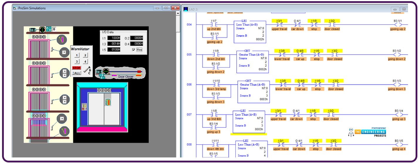
Figure one shows the details that might help me describe the project between our hands. We have an elevator car that travels up and down and can stop on one of four floors based on the passengers’ requests. We have 6 push buttons on the wall next to the elevator door that can send requests to call the elevator. In addition, there is a control panel inside the elevator cabinet in which there are push buttons to request stations to reach floors 1, 2, 3, or 4. So now we are requested to manage all the scenarios and all requests received from inside and outside the elevator considering the priority of these requests to save energy and time management for the elevator traveling route. In the next section, the detailed requirements are listed.

The project requirements

The elevator should save all requests from the time they are requested until they are processed and cleared from the to-do list. 

The elevator should prioritize the requests in their direction of movement. For example, while he goes down, the requests for places located below his position will be given priority to do first. Similarly, when he goes up, the requests above the position where he is will be given priority. In that we, the waiting time will be reduced, and the energy and overall travelling distance will also be minimized. Because we have a lot to present in this significant project, let’s move on directly to the design and the ladder logic program that handles these requirements.

The design and logic of Elevator System

As usual, we are going to apply the divide-and-conquer rule. So the project will be divided into subtasks, and each task will be managed by one subroutine all subroutines are called in the main routine in sequence. Figure 2 shows the program structure which is composed of 5 subroutines. In the first routine, all initializations are called to be executed. So what’s in these subroutines? That is what we are going to show you below. So please follow up, my friends.

Figure 1 shows the ladder logic code of the first subroutine that initializes the work to start with the first floor as the initial position and going up as the initial moving direction and activate the action of performing the subsequent request or waiting for an incoming one.

The next subroutine is the heart of the logic, as it saves the requests and energizes the light indicators of the requested doors. Figure 3 shows a portion of the routine’s ladder logic code. As you notice, my friends, the first line is to tell the compiler that this is the start of the subroutine. The rung number 1 check if the request push button of the first floor inside the elevator’s car has been pressed and the elevator is not on the first floor; it will light the button lamp to show there is one request in the queue until the time comes to perform that request then the light will be turned off as we will demonstrate to you, guys. The next rungs, rungs number 2, 3, and 4, do the same for the corresponding keys inside the elevator’s car. If a push button is pressed, and its requested floor is not the current floor where the elevator is, then the corresponding lamp indicator is lighted, showing the request is saved in the queue, and when it is processed, the lamp indicator will be turned off. Now, moving on in the code, rung number 5 handles the outdoor request from pressing the first floor up push button. It simply checks the floor location. If it is not on the first floor, it lights; the lamp indicator of that push button shows that the request is in progress and will be turned off once it is processed. The following rungs do similarly the same function. But notice we have one push button for floors 1 and 4 while there are 2 push buttons for floors 2 and 3. So there are two rungs for handling the up and down direction requests.

One remaining thing for this subroutine is that the last rung confirms that when no requests are there so, the light on the first floor is turned on, showing that the elevator is on the first floor. Now my friends, let’s move to the next subroutine.

The next subroutine is called “track the vertical travel.” As you see, guys, the code checks in rung number 1 if the elevator is on the first floor, then it lit the first-floor light indicator and unlatched or de-energized the previous floor light, which is on the second floor and stops and opens the door. Now, when it reaches the second floor, indicated by the I:5 encoder, it lit the second floor and de-energized the lights of the next floors up and down, which are the first and third floors. Also, it checks if the second floor is being requested or in the queue list, then it stops the elevator and opens the door for getting or charging people who requested the second floor.

Figure 7 shows the ladder logic code of the second and last part of this routine; rung number 3, for example, checks if the elevator has reached the third floor; in this case, it lit the third-floor lamp indicator and turned off the next floors’ lamp indicators, i.e. floor 2 when it moves up from floor 2 to floor 3, or floor 4 when it goes down from floor 4 to floor 3. Also, if it goes down and the GO-Down request of the third floor is pressed, meaning there is a request in the queue, then it stops the elevator and opens the door for charging or discharging people who target the third floor. But, if it is going down and the Go-down, it stops the elevator and opens the door for charging or discharging the people.  And the last rung, number 4, handles the 4th-floor requests. If it is on the 4th floor, it just lights the light indicator on the 4th  floor and turns the light on the 3rd floor.

Now, my friends, the next routine is called “stop and open,” that handles opening the door at each destination. Figure 8 shows the logic; in rung number 1, if the door is not open for 2 seconds, then it is open the door, gives some time and then performs the subsequent request. When the door is opened, the request for the first floor is cleared. When it reaches floor number 2, and the door opens, if it goes up, clear the floor lightly and push the button to request the second floor, similarly, for the third and fourth floors.

Figure 9 shows the ladder logic code of the routine that decides which door will be bypassed and closing the door and go. It is called “ Do next or wait.” You can see, guys, it easily compares the moving direction and the requests in the queue based on the light status of the push buttons of all floors. Then bypass and resume with the door closed or wait and open the door for charging or discharging people.

Figure 10 shows the routine for closing the door at destinations. The routine is called “close door and move.” It simply checks if the door is closed and going up is requested, then lunch the move up the direction. But, if it is requested to move down, then latch the motor moving down. If no requests are moving up or down, enable the between-floors status. Now, my friends, we have explored all subroutines, and the time to test our logic and ladder logic program and subroutines has come. So let’s see if it is correct or needs some amendments.

Testing the ladder logic code

Figure 11 shows the initial state of the program while the elevator stops at the first floor, and the light indicators show the light of the first floor is lit, as you can see, my friends. Now let us command the push buttons requesting many requests to test.

From the initial position where the elevator is on the first floor, figure 12 shows the elevator has been requested as follows: on the second floor, it is requested to move up. On the third floor, it is requested to move down. On the fourth floor, it is requested to move down.

According to the requests and the sequences, it starts the journey from the first floor and stops at the second floor, as shown in figure 12.

Continuing his journey, he bypasses the third floor because it needs to go down. Show it gives priority to the request on the 4th floor, which is in his moving direction, as shown in figure 13.

Now, after reaching the most up, it changes direction and goes down to reach the third floor, which is the last request, as shown in figure 14. Notice, my friends, every time it reaches one requested place, it clears the light of the belonging request.

What’s next???

Clearly, the test successfully showed one scenario with all the test cases of moving, stopping, and bypassing. Thank you, friends, for following up on these points, and I hope you have enjoyed the project we have done together in this tutorial. Also, I promise the next tutorial will come with a new project from real life and learn more and enjoy practicing ladder logic programing together. So stay safe and be ready for our next tutorial.

Four floors Elevator using ladder logic programming

Hello, my friends and welcome back with one new tutorial of our ladder logic programming series. Today I am bringing one exciting project which you can see everywhere, in your home, work, and public places, which is an elevator. We will design a solution using plc ladder logic programming, which drives the elevator. Our elevator is composed of 4 floors and has all capabilities of large-scale elevators. So let’s get started and save time and jump into our tutorial.

Elevator Project

As you can see, Everyone figure 1 depicts the complete scene of the project and tells that the elevator we will manage has four floors to visit. On the first floor, there is only one outer request to call the car from any floor above, i.e. from floor 2, floor 3, or floor 4. While on the second floor, there are two request buttons to get the car from up or down floors and the same for floor 3. But floor 4, the last floor, has one request button to bring the elevator from the below floors, i.e. floors 1, 2, or 3. Also, the figure shows the request buttons inside the elevator car. There are request buttons for each floor, one-stop button, and one call button for emergencies. Now let’s move on to the inputs and outputs we will use in our logic:

Project inputs and outputs (IOs)

Smartly, we wrote one rung ladder logic as shown in figure 2, which does nothing but show the IOs the project has and names each IO with the descriptive name. We typically do such a rung for listing all IOs in one place to see the status of all IOs with one look. So what IOs do we have in this project? Well! You can see the request push button on the first floor from right to left and connected to input I:1/6. Also, the lamp indicator shows that the request is in progress. That indicator is connected to output O:2/6. In the second column, you can notice my friend’s two request push buttons connected to digital inputs I:1/9 and I:1/7. Also, for each request push button, there is an indicator lamp. The indicators of up and down requests for the second floor are connected to digital outputs O:2/9 and O:2/7.Similarly, in the next column, two push buttons request the elevator car to come from up or down; the request push buttons of the third floor are connected to digital inputs I:1/10 and I:1/8. Also, indicator lamps of the demands of the third floor are connected to digital outputs O:2/10 and O:2/8. And floor four has only one request push button and one indicator lamp associated with I:1/11 and O:2/11, respectively. It is essential to let you know that there are two safety limit switches to govern the travel limit in up and down directions. Digital input I:3/0, the one represents the lower limit travel while I:1/4 holds the upper limit travel signal. Also, there are inputs for the indoor control panel, as shown in the figure below. For example, indoor floor requests are connected to digital input I:1/1, I:1/2, I:1/3, and I:1/4 for requesting the first, second, third, and fourth floors. In addition, there is one push button to stop and another to call.

Design of elevator

Once more, let me remind you, my friends, that the best way to make it easy is to divide and conquer, meaning we break down the whole mission into sub-tasks and complete them to integrate at the end of the day for having the entire task achieved. Now, what are the requirements? Good, you ask such a question. Well! Our clients provided us with the image shown in figure 1 that gave us some details, but we still need to list the requirements and validate them with the customer before going further. That is crucial, my friends, because going further without confirmation of the conditions might yield some conflict later at a point in time. We will have made many efforts to cost many working hours that we want to retain. So again, what are the requirements? We need to recognize the position where the elevator is at any moment. Also, we need to command the elevator to go up or down based on where it is and the requested position. So now let’s divide the project into two main tasks. Determining the elevator position is our first one, and performing the requests will be the second task. So now, let’s move forward to the logic and coding of our ladder logic program.

Elevator ladder logic task 1

As we have mentioned earlier, in task 1, we want to determine the position of the elevator to decide where to direct the elevator up or down when one request comes. For example, you assume the elevator is on the 3rd floor, and a request comes from the second floor to call the elevator car. So, in this case, the logic of the program should command the elevator to go down. But if it was located on the 1st floor, in that case, it should direct in the up direction. Before going further in the position determination, we will show you how to manage the elevator door. Because we can not command the elevator to move while the door is open, figure 3 shows the door control lines of code in ladder logic programming. In rung number 2, we design the logic so that if the car is not moving up or down for a while, the door will be commanded to open by using the latch and unlatch command. In rung number 4, the door will be closed when the elevator does not move up or down, and the door is not opened or closed.

For testing the opening and closing management of the elevator door, Figures 4 and 5 show the door while opening and closing actions.

Ladder logic of elevator position

Figure 5.1 shows the ladder logic code for determining the elevator position; it utilizes the encoder’s feedback or reading and compares it using the limit instruction given the limit of each floor. For example, if the value reported by the encoder is between 293 to 295, which is the limit position of the first floor so, save one into the variable N7:0 that holds the current floor where the elevator dwells. And similarly, decide on the second, third, and fourth floors based on each floor's limit and the encoder's reading.

Now my friends, let’s move on to describing the code of the program step by step. Figure 6 depicts the ladder logic of the request handling logic. As you can see, my friends, in rung number 4, the requests from the second floor are being handled. When a request to move upward comes from the second floor, we test the elevator’s current position. If it is less than the requested position, which is floor 2, then it would go up. But if the position of the elevator is the upper floor, i.e. the 3rd or the 4th floor, then it should go down as instructed thanks to rung number 5. So let’s test this logic and see if it fulfills the requirements.

In the next step, after knowing the direction in which the elevator should move,  we code the commands to drive the motor to move up or down, as in figure 6.1, using rungs 10 and 11.

Testing the second-floor requests

Figure 7 shows the first scenario when the elevator was stopped on the first floor and was requested from the second floor. It shows the elevator goes up to its new requested target.

Figure 8 shows the second scenario when the elevator was stopped on the 3rd floor and was requested from the second floor. It shows the elevator goes down to its new requested target.

Figure 9 shows another test scenario when the elevator is requested to move from the second to the third floor.  Success is the result shown in figure 9 as it shows the elevator is moving up from the source place to the destination, the third floor,

Figure 10 depicts another test scenario of a request initiated from the third floor when the elevator is requested to move from the fourth to the third floor.  Success is the result shown in figure 10 as it shows the elevator is moving down from the source place, the fourth floor, to the destination, the third floor,

Figure 11 demonstrates another test scenario of a request initiated from the 4th  floor when the elevator is requested to move from the third floor.  The elevator moves up from the source place, the 3rd  floor, to the destination, the fourth floor,

Figure 12 shows another test scenario of a request initiated from the first floor when the elevator is requested to move from the third floor.  The elevator moves down from the source place, the 3rd  floor, to the destination, the 1st  floor.

What’s next???

First of all, I hope you have enjoyed the elevator project; please go through the tutorial and try to code the ladder logic and test it yourself for the best gain you can get from the tutorial. We have presented in this tutorial only some of it; we have done much great work, but we still have much work to do to complete the elevator project. So next time, the remaining project logic will be demonstrated, and you will enjoy learning and practicing ladder logic programming. So please stay safe and be ready for our following tutorial.

Bottle Line Scraping Management system using PLC Ladder Logic

Hello everyone, and welcome back with a new tutorial in our ladder logic programming. Today we will continue the bottle line production line using ladder logic programming. Let me remind you, everyone; we have seen how to utilize the bit shift left instruction BSL to save the data that describes the state of a bottle, including the present state, size state, either large or small size and the excellent and broken state as well. And also we utilized these states to energize the large bottle and scrap solenoid to divert the bottles to the appropriate position and conveyor. At the end of the day, we have separated small, large, and scrap bottles. Today we are going to manage the scraping of the broken bottle.

Bottle line Scraping management 

In each bottle line process, we have a common and critical problem with removing and eliminating the scraping of broken bottles. Figure 1 shows that on the main conveyor, there are broken bottles. We need to prevent them from processing and take them out to be ground and removed. We have a conveyor on the second row on the left for this mission. For what? For collecting the output of the grinder in boxes, as you can see on the conveyor, take them out of the line. That outlines what we need to do, but how about the details? Follow up, and you will get to know.

Project Requirements

In this project, we need to pick the broken bottles, diver them to the grinder, and take the scrap through the conveyor out of the process. Many subtasks we need to do, like deciding on the broken bottles and classifying them into large and small for the size of the scrap boxes, given that the large bottles are 2/3 and the small bottles are 1/3. Also, one sub-task activates the scrap driver solenoid on time when there is a broken bottle. Also, the grinder needs to run all the time. And we are counting the broken and good bottles by classifying the size of the bottles. We have been requested to do this task to avoid the scenario of unmanaged scraping, as shown in figure 2.

The inputs and outputs associated with this process

Table 1 lists the IOs of the process, including the name, addresses, and descriptions. These are not all the IOs in the project. We will use these most important parts to develop the scrap management process.

-

Addresses

Description

Scraping gate

O:2/4

Solenoid to control the scraping gate

The Grinder

O:2/3

The grinder motor for grinding the broken bottles

Box sensor LS10

I:1/15

The limit switch to detect the boxes edges

Scrap conveyor

O:2/1

The conveyor motor of the scrap 

Selector switch A

I:1/2

To select and control the counters display (small bottle)  

Selector switch B

I:1/3

To select and control the counters display  (large bottle)

Selector switch C

I:1/4

To select and control the counters display  (scarp)

Screen BCD

O:4

The screen BCD output

Screen small bottles control

O:2/11

The output to control the small bottle display

Screen large bottles control

O:2/12

The output to control the large bottle display

Screen scrap bottles control

O:2/13

The output to control the scrap bottle display

Screen boxes control

O:2/14

The output to control the boxes display

Projects ladder logic program

Because the logic is extended, we will present it piece by piece. Figure 3 shows the first piece of the scraping removal process. Describe this to you, my friends; the first rung runs the large bottle size diverter solenoid by sensing a presence of a large size bottle thank to using the match bit of the 32 bits of the saved register B3:6 and B3:7. Similarly, rung 3 energizes the large bottle conveyor to give space for the next bottle and prevents the crash from happening. The third rung is not that different; it runs the broken bottle diverter thanks to the saved broken bottles in 32 bits of b3:8 and b3:9. Then counter of type count up is used to count the large, the small broken bottles, and the large broken bottles.

Figure 4 shows the second portion of the ladder logic program of the scrap management process; you can see, everyone, in rung number 9, the multiply instruction is used to calculate the 2/3 and the 1/3 portion of the large and small bottles. And at the end, we use add instructions to get the sum of the total scrap. For the logic sequence, let us jump just a moment to rung number 11, which checks the sum we have obtained in tinged nine that represents the whole amount of scrap, including the small and the large bottles—testing using the LIM instruction to see if it is between the limit of the capacity of the box. If it is within the boundary of total capacity, the box should move by commanding the scrap conveyor. Backing to rung number 10, it is when the box reaches the limit switch position that the counter is reset to start over the scraping cycles. Counter reset includes the large and small size bottle counters.

Testing the scrap process

After completing the requested logic, we will check it, as shown in figure 5. This screen capture of the run process is brilliant because it shows all the subtasks we need to do in this project. First, you guys can see one of the broken bottles goes to the grinder once it has reached the correct position.  Also, you can see the small bottles going on the main conveyor and the large bottles going over the large bottles conveyor. Also, the most important thing you can notice is the filled boxes on the scrap conveyor in the second row and on the left. You can see boxes are being filled and moved through the scrap conveyor. The boxes are not equally filled because the limit we set is composed of 2/3rd of the large bottles and 1/3rd of the small bottles when we need to know how many of each we might have each time. We can continue tuning the limit in the code until reaching the most utilization of the box size.

Figure 6 shows how using the scrap boxes happens by adapting the limits in the LIM instructions.

The last part we need to do to complete the scrap management is to display the counters on the displays we have. We need to display the small, large, and scrap counters on the screens on the bottom right part of the project screen. Figure 7 shows the piece of code of our ladder logic program that does that logic. It is just moving the counters’ accumulators to the BCd outputs based on the output control bits controlled by the selector switch's inputs. For example, to display the small bottles processed so far, we energize the output O:2/11 when the selector switch is at position A and then use that output to invoke the MOV instruction to move the values from the small bottles counter accumulator to the screen output O:4. Same scenario to manage all the screens for the large bottles, and scrap bottles counters.

Testing the displays

Figure 8 shows how successful the counter’s accumulators have been displayed on the BCD screens thanks to the last piece of code of the ladder logic program we discussed.

What’s next???

Thanks so much, my friends, for following up on the end of this tutorial, in which we have covered a good part of the bottle line project. That part was about getting rid of the scrap and classifying the bottle based on size, small and large. Also, we have shown how to display small, large, and scrap counters on the BCD screens. Next time we will complete a critical part of that project: filling and capping the bottles by completing the code that manages the capping station and filling station. So please be there, and I hope to see you soon with our incoming ladder logic programming series tutorial.

Bottle Line Filling and Capping system using PLC Ladder Logic

Hi, my friends, and welcome back to enjoying together learning and practicing PLC ladder logic programming with a new project from the actual industry. Today my friends, we will continue the bottle line project to complete the capping and filling of the bottling line. As usual, we will describe the requirements as the clients ask us to do. Then we list all the inputs and outputs we will use to make our design work. Afterward, we write the ladder logic program into two sub-tasks. We make one to perform the filling and the second for the capping process. So, without further delay, buddies, let’s jump into the work.

Filling and capping project

Let me introduce the project as two processes we have been requested to implement here. We are filling bottle process in which we need to control the filling station that has two supplying sources to fill the small bottles and the large-size bottles with two different liquids. Figure 1 shows the filling station that offers two sources of liquids: the orange-coloured liquid for the large-size bottles and the violet-coloured liquid to fill the small bottles. So we need to identify the type of bottle that comes to the filling station—then, based on knowing which bottle type, we need to open the valve of the appropriate filling tube. Remember to stop the main conveyor while the filing process is in progress. Once the filling has been done, we need to resume the movement of the main conveyor.

Moving on to the capping station, figure 2 shows the capping station that is nothing but a cylinder to let the cap released to the bottle that reaches the capping station. Now you can see my friends, inputs and outputs are listed and named on the filling and capping station. We need to list these inputs and outputs and see how we can employ them to complete our project. Please note, buddies, the recorded inputs and outputs in table 1 are not all project IOs. They are only the IOs belonging to the filling and capping process. So you can add these IOs to the list of IOs we have previously introduced in the last two tutorials.

Filling and capping stations IOs

Table 1 tabulates the list of IOs of the project, including names, addresses, and descriptions. As you can see, everyone, all information, including the item name, addresses, and description of the filling station, are in the table below and ready for your turn to use them in the logic of the program you will write.

Item name

Address

Description

LS1 filling 

I:1/9

This level switch tells if the bottle is filled or not.

Filling actuator solenoid SOL1

O:2/6

The filling valve actuator

valve1

O:2/7

Purple liquid tube valve actuator

Valve2

O:2/8

orange liquid tube valve actuator

LS 2

I:1/10

Sensor to detect the filling position of the orange-coloured liquid for the large-size bottles

LS 3

I:1/11

Sensor to detect the fill position of the purple for the small size position 


Similarly, table 2 lists the inputs and outputs that could be used throughout your program to achieve the requirements that your client has requested. Now, folks, our clock says the time to design and code the ladder logic program of the capping and filling system. so let’s go nailing the two processes.

IO name

Address

Description

LS3

I:1/12

The position sensor of the cylinder actuator of the capping station

Capping Actuator solenoid SOL2

O:2/9

The solenoid for actuating the cap pusher in the capping station 


Design of the filling system

Remember that we already have the status and all information about the incoming bottles saved in data files from the last two tutorials named bottle project. So you can stop by these previous two tutorials to feed your memory we the information you are going to use here. Now, we need to decide which bit to use to control the filling tube and valves and manage the filling station. Yes, by noticing the filling scenario depicted in figure 3, you can see, everyone, all that we need is the bit at the filling actuators and the bottle size. So let’s clarify by discussing the ladder logic code we wrote for the filling process.

Filling process ladder logic code

Figure 4 shows the few ranges that implement the task of controlling the bottle filling. In the first rung, we added all the conditions at which the main conveyor should stop as a normally closed contact to stop the conveyor from moving while capping, filling, and processing. In the following range, we use the existence bit to ensure there is a bottle to fill and not broken and one-shot instruction to fire the extend the cylinder of the filling actuator. And the following two lines, we activate the large-size bottle valve when the bottle we fill is large or start the one for filling the small-size bottles. And finally, we complete the process by returning the piston of the filling actuator once the bottle, either the small or the large, is filled.

Testing the filling process

As you can see, the filling ladder logic code that we wrote can manage the filling for both bottle sizes, the small with the violet-coloured liquid and the large with the orange-coloured liquid. By identifying the correct position of the bottle at the filling actuator and the right size, the code opens the correct valve to fill with the appropriate liquid for each bottle type. Now, it’s the turn to handle the capping station work. So let’s go doing it; it’s pretty easy!

Capping station design and ladder logic coding

Similarly, we need to identify the correct bit at the capping station and check that it exists, is filled, and is not broken. Thereby we can command the capping actuator to do capping the bottles. Figure 6 shows the simple ladder logic code that handles the capping process. SiIts checked that the bottle was there and not broken. Afterward, it uses one-shot instruction to fire the capper actuator. And the following range unlatches the capper actuators once it has reached its target, thanks to the extended limit switch. Now let’s check the correctness of the code we just wrote.

Figure 7 shows the results of successfully running the whole process filling and capping process. You can see my friends when bottles come to the filling actuator; they are filled with the appropriate liquid based on the bottle size. When they reach the exact position where the capper is mounted, the capper actuator is activated to process the capping successfully.

What’s next???

I’d love to say thank you, my friend, so much for following up with me and my tutorial up to that moment. I hope you have learnt something that increases your knowledge of ladder logic programming and that you have enjoyed practicing one project from the entire industry. We do nothing but bring what we have done in our practical life in industry in the form of tutorials and simulations to take you close to what is going on in the factory every single day for you become familiar with whatever you will see in your future work. For what is incoming? Without question, I will bring a new project from the factory and enjoy learning and practicing together. So stay safe and be ready to meet very soon. 

Dual Compressor Operations using PLC Ladder Logic Programming

Hello, my friends, again we are back and enjoying one of the new tutorials in our ladder logic programming series. The tutorial we are here to present comes with a new project: dual compressors management using PLC. In that very project, you are going to learn how to divide the process between two actuators aiming to prolong the lifetime of the equipment and fulfill the processing requirements. as we used to do every tutorial, will go through the project. Understand the requirements, and design for the solution. And then code the ladder logic program of the solution and for sure enjoying simulating the code to validate the functionality of the proposed code. So without any more delay, let’s get started on our project.

What’s dual compressors project

The picture of the project shown in figure 1, can tell everything about the project including the sensors and actuators. The project utilizes two compressors to fill the tank with gas. Sometimes one compressor is enough, and some time needs to have both compressors work together to compensate for the heavy-duty demand. So now, which compressor will be in charge based on the demand and for prolonging the equipment’s lifetime? These kinds of problems are our mission to figure out a workable ladder logic program to handle the whole process. The image shows all details you need guys to complete the project. Inputs and outputs, switches, push buttons, indicating lamps to tell process status, screens and BCD Displays.

Project inputs and outputs address and description

Table 1 shows the inputs and outputs of the process, telling the addresses and the description of each component. The first column list the inputs or the outputs of the process, column 2 lists the dedicated address of the Ios, and the description of these Ios is told by the 3rd column. 

Item 

Address

Description

Run

O:02/02

Lamp indicator to show the process is running

C1

O:02/03

The lamp indicator shows compressor C1 is ON

C2

O:02/04

The lamp indicator shows that compressor C2 is running 

A, B, C

I:1/4 I:01/05 I:01/06

3 position selector switch to select which amount to display

start

I:01/01

Start the push button to commence the process

Stop 

I:01/00

Stop pushing a button to halt the process momentarily

BCD display

O:4

A BCD to 7-segment display

PE1

I:01/02

Pressure switch 1

PE2

I:01/03

Pressure switch 2 

M1

O:2/00

The compressor motor number 1

M2

O:2/01

The compressor motor number 2

The PSI

N/A

Display the current pressure in PSI

Flow %

N/A

Setting the flow percentage by regulating the valve 

The project coding

As I want you to learn how to apply the divide and conquer technique of programming, I’d like us to divide the project into parts, small, simple tasks. By combining them all, we get the whole process done. So now let’s start by running a single compressor and stop it based on user requests having the process status shown by indicators and displays that we have and listed in table 1 above.  Figure 2 shows the code for running in single actuator mode. So one compressor will take charge and start by hitting the start push button while it is stopped either by hitting the stop push button or by reaching the high-level pressure indicated by sensor I:1/2. Also, you notice my friends, the lamp indicators for showing the process status, like Run status and which compressor is in charge now.

Switching between the two compressors 

Realizing the dual operation concept in which we should use both compressors equally one for each cycle, figure 3 shows the ladder logic code to do so. You can see the project is getting bigger by adding more tasks. but let’s go through the line we have written so far, as shown in the figure below. Firstly we have latched the run status by hitting the start push button in the first runge. And the coil of the first compressor activates the indicator lamp of the first compressor as in the 2nd range. Similarly, the second compressor relay coil energizes its indicating lamp. In the fourth and fifth rungs, the formula is based on which the program can decide which compressor to run. Each compressor depends on its pressure switch. Compressor 1 works as long as the pressure measured by PE1 is within its limit, and compressor 2 works as long as the pressure measured by PE2 is within its limit to run. However, you notice, guys, there is one bit which is B3:0/0, which we have used to decide which compressor to choose to run each cycle. That is why it is XIC for one and XIO for the other compressor guy. But wait, how will we know the cycle ends, and a new cycle is to begin? Well! It’s the sixth runge that reads the one shot of the I:1/2 to change the status of B3:0/1 each cycle and, in turn, change the compressor. And notice, guys, the most intelligent runge, the last rung that flips the flag B3:0/0, which is responsible for flipping the operation from one compressor to the other. Now, the time to test all that we have done of coding comes to see if it is correct or needs to amend for correction. So let’s go test our ladder logic code.

Testing the dual compressor operation

Figure 4 shows the first case when we hit the start push button, compressor C1 started working. And it keeps working as long as the pressure PE1 reads is less than 40 PSI, as you can see in the figure below. Compressor C1 is running and sufficient to fulfill the process requirements. Also, my friends, see the control panel showing the status of the running compressor is ON, highlighted in yellow, while the other compressor guy is off as indicators tell.

In another case, figure 5 shows when both compressors are off because the operator hit to stop the push button to halt the process. See the indicators of both compressors are off, and the run process is ON, waiting to hit start to resume the process.

Now, time to start a new cycle, remembering the last time compressor C1 was working. Notice, guys, our code’s success in switching to the other compressor, C2. The flip flag in the last range turns on to flip the compressors from one to the other smartly. Also, the indicator panel shows the compressor C2 lamp is highlighted while the other guy’s light is turned off.

One last thing to consider, my friends, is when we run at a heavy demand of using the tank. One compressor won’t be enough to fulfill the heavy-duty process in this condition. Therefore, we need to have one case to run compressor C1, the other to switch to compressor C2, and the third case at heavy-duty we need to run both compressors C1 and C2 together to fulfill the heavy demand. Notice my friends in rungs 003 and 004, the change we have made is just adding a parallel branch to override the flag switch to give a chance for both compressors to work regardless of the flag when heavy duty is on that detected by PE2 pressure switch when it lowers than 95 PSI.

Testing the heavy-duty case

Figure 8 shows the case of running under high demand and reaching toe heavy-duty operating conditions. See how successfully our ladder logic program can run both compressors to fulfill such heavy-duty conditions. Also, please notice that the indicator lamp of compressors C1 and C2 are on when the heavy-duty flange is on because the PE2 marked pressure under 95 PSI, the lowest pressure based on the setting on I:1/03.

At last, I would like to thank you, my friends, for patiently following me until the end of this tutorial. Hoping you have got some benefits and learnt some new practices with the project we went through in this tutorial. Please stay safe, and let’s meet soon with another tutorial to enjoy learning and practicing ladder logic programming.

Bottle Line Assembly using PLC Ladder Logic Programming

Hello friends, we are going to learn and practice together one project from the industry. It is the bottle line production in which many processes are happening, including but not limited to filling, capping, and conveying from the start point where the bottles get in the line to the end point where the bottle gets out from the line. In the process, many concerns and restrictions must be addressed, like the bottle size, length, broken status, pretty full or empty, etc. So we have a lot to learn, program, and test right here in this project. Let’s jump into work and enjoy completing such an exciting project without further delay.

Bottle Line Assembly: Introduction

Figure 1 images the project we are going to do. Yes, it’s a massive project, with too many things we see to control. However, it’s not hard to be done because we grew up to be experts in ladder logic programming. Furthermore, we will apply the critical secret to make the large project easy, like a piece of cake that divide and conquer methodology. That can be happened by breaking down the whole project into small pieces and integrating these implement small pieces to have the entire process happen at the end of the day. Moving to the project itself, we can say we have two lines in the above line to describe the image shown below. The bottles are going to meet from left to right. The first sensor of proximity type sensor to check the presence of a bottle, and the next sensor of type limit switch to check the bottle size. The following sensor of type proximity is to check the excellent and broken bottles. Moving forward to the right, you can see guys at the filling station that can fill the small and large bottles. Then you will know the capping station. Also, we have a couple of motors being utilized to drive that project; the main engine in the first line, which is mounted at the left underneath the conveyor, moves the bottle forward from entry to the end. The second motor is mounted at the left of the second conveyor at the left that is used to move the output of the grinder of the broken bottles. The grinder motor on the following line properly grinds the broken bottle. The other engine installed at the third conveyor at the right is used to drive the final product conveyor. Also, you can see dozens of inputs and outputs, including sensors, switches, motors, valves, solenoids, and indicator lamps. The following section will list and describe these inputs and outputs in detail.

The inputs and outputs of the project

One of the most common and regular tasks you guys should do is tabulate the inputs and outputs in the project you develop. Table 1 below lists all the IOs in the project showing the names, addresses, and descriptions. I hope I have caught all of the IOs I listed in the table below; you can see, everyone, how important to have one table that lists all the inputs and outputs you need to use throughout the implementation process. The first step to start is to listen and write down the requirement and the philosophy of the logic of the process you will implement by listening to your client who requested that work from you. Feel free to ask them to confirm and validate the requirements once you have all requirements and narratives of the logic written down. You can go to the next step, designing the logic and breaking it down into small, simple parts. From there, you can start writing the ladder logic of each part and later integrate these parts to have the whole project done.

Name

Address

Description

Start

I:1/1

Commence the process

stop

I:1/0

Stop the process

Selector switch

I:1/2

Mode A operation


I:1/3

Mode B operation


I:1/4

Mode C operation 

Enter

I:1/5

To enter the setting value

Small bottle BCD

O:2/11

The digital counter of the small bottles

Large bottle BCD

O:2/12

The digital counter of the large bottles

Scrap parts BCD

O:2/13

The digital counter of the scraps

Boxes BCD

O:2/14

The digital counter of the boxes

Scrap conveyor

O:2/1

The scrap conveyor driver

Divert conveyor

O:2/2

The divert conveyor driver

Ls10

I:1/15

Scrap Boxes limit switch 

Grinder

O:2/3

The grinder driver

Divert gate

O:2/5


Scrap gate

O:2/4


The Main conveyor

O:2/0


Ls1

I:1/6

Limit switch to see bottle presence

Ls2

I:1/7

Limit switch to see scraps

Ls3

I:1/9

Limit switch to determine bottle size

LS5

I:1/10

Large bottle fill

LS6

I:1/11

Small bottle fill

LS7

I:1/12

Capping limit switch

LS8

I:1/13

The limit switch to detect scraping ready position

LS9

I:1/14

The limit switch to detect readily divert

Fill tube 

O:2/6

The fill tube valve

Cap Ram

O:2/9

The cap Ram


Bottle Line Project: Requirements

Because we plan to divide the project into small, simple parts, we also will present the requirements in parts. 

Part 1: start and stop the process of saving the bottle states 

In the first part, we are required to start the process by energizing the main conveyor motor, hitting the start push button, and stopping the process whenever the operator presses the stop push button. In addition, we need to save the states of the processed bottles, including the present state by using the LS1 limit switch, the bottle state (broken or good) status by using the LS 2 limit switch, and the size state (large or small) giving a hint that we can use bit shift left instruction. This requirement looks simple but wait, it’s just the start and also optimistically all parts of the project can be that simple by dividing your project into parts remembering the divide and conquer rule. So let’s do the first part.

The logic of the first part of the project

Figure 3 shows the simple ladder logic code of that part. The first rung is commonly known to latch the run status and the main conveyor by hitting start. But stops when pressing stop. The third rung uses the presence limit switch to call three-bit shift left instructions. In the first, the value of the reading of LS1 for existing status is saved in the 32 bits of the addresses b3:4 and b3:5. Similarly, the second BSL is to save the broken and good states, which is the readings of the LS2 in the 32 bits of B3:6 and B3:7. And in likewise the third BSL instruction saves the readings of the LS3 which is the size state of the bottles in the 32 bits in B3:8 and B3:9. Let’s simulate and show you guys how that works and what is the benefit of using BSL instruction?

The simulation and testing of part 1

Figure 4 shows the output of the execution of the part 1 simulation. You can notice, my friends, that the data files of the 32 bits in B3:4-B3:5 reflect the status of a bottle to LS1, and they are always 1’s because all bottles, regardless of the status, size, and case of the bottles. They are always there and seen by the sensor. For sensor LS2, it is a different story, as shown by the B3:6 and B3:7; the broken bottles show 1’s while the good ones show 0’s. Same for the LS3 that tells the size, the saved data in B3:8 and B3:9 shows when it is a large bottle by 1’s and small bottles by having the value 0’s. So you notice, my friends, we have completed the requirements of the first part, which seems simple, but it is essential because we now have the status of the bottles’ states, including presence, size, and excellent or broken bottles. We can now use the saved data to process the following requirements. So let’s do another part of the project.

Project part 2: Ladder Logic Program

This part of the project requires you guys to divert the long or large bottle to the diverter place on the right. Now it is time to use the data you saved in the first part of the project. Because you have the size of all incoming bottles, you can test the appropriate bit and command the solenoid to extend to open the divert gate when the bit is high. But wait a minute, which bit of the saved 32 bits do we need to do the test and decide? That’s such a brilliant question. Well, we need to count up from the position of the sensor LS2 that tells the bottle size until the point where the diverter is installed. By counting, we can see 20 bottles between the two positions. So if the data is located in B3:6 and B3:7, the bit we are looking for to use in testing is B3:7/4. So let’s try to see if that is correct or if we need to amend and correct that initial thinking that we thought.

Project part 2 

Figure 5 shows the minor modification we have added to fulfill what is requested in part 2. You can see, everyone, we have just added only one rung, which is the third one that says when the bit b3:7/4 is on, that means there is a bottle of an extended size that needs to be diverted. Therefore, the diverter solenoid is energized for that purpose. Ohh! We forgot to consider that we need to move the diverter converter to avoid the possible crash when another bottle comes over the previously processed one.

So when do we need to command the diverter conveyor motor to run for moving the conveyor? The answer is shown in figure 6; as you can notice, for everyone in rung number 4, It is a good idea to use the last bit, which offers a large bottle to move the conveyor to empty a slote to the incoming bottle. Therefore, we added one more rung to command the diverter conveyor motor when the last large-size bottle is presented. So now Let’s see the result of running this logic.

Simulation of part 2

Figure 7 depicts the results of testing the logic we have written so far up to part 2 of this exciting project. You notice how successfully the long-size bottles are rowed side by side. Yes, you can see the broken bottles are also included, which could be better, and that is what we will do in the next part. So let’s continue completing our project.

Project part 3

Now everyone, let’s move to a little bit harder part in which you must manage the scrap by activating the solenoid of the scrap gate to open when there is a broken bottle. Also we need to count the processed bottles, including small and good, large and sound, and scrap bottles. I know this time we asked many things to do but believe me, as you divide your projects into parts, as we do, it will be easy tasks. So now let’s see how to do the requirements for this part. Figure 8 shows the ladder; logic rungs for part 3. You can see guys in rung number 4 that we energized the gate when the bit b3:8/8 is ON. Why the eighth bit? Because the number of bottles between the sensor LS2 that detects broken bottles and the gate mounting point is eight bottles. The other four counting rungs from 5 to 8 are for measuring the small valid bottles, the large size bottles, and scraping bottles correspondingly. And at last, we summed the small and large broken bottles to get the total scrapped bottles. So let’s do one test for the code so far.

Simulation of part 3

Figure 9 shows the broken bottle has been diverted through the scraping gate, the large size redirected to the diverting gate, and the small valid bottles go onto the upper conveyor.

What’s next???

As you have seen in this tutorial, many tasks exist. We already have done a lot but still, have much to do together in this project. So following the tutorial, we will complete the filling bottle station and the capping station to deliver a complete project and production line. So be there and see you in the following tutorial very soon.

Automatic Batch Mixing Tank with PLC Ladder Logic Programming

Hello friends, welcome back to our tutorials on PLC ladder logic programming. Today we will talk about batch process control and take one project from our factory to understand, implement, and simulate. So without any further delay, let’s jump into the tutorial by asking what is batch process is if it is different from other online processes. Well! The batch process is defined as a process that starts by operating continuously till the end of the cycle without any interaction with the users. For you guys, it’s cool to know that most of the processes you might meet in the industry of batch-type processing. Do you like me to give an example? Well! The Silo cement process is a batch process, and food and beverages manufacturing are also good examples of batch processes. So what do we have today of the batch process? It’s a batch-mixing process in which we mix liquids with a mixer. The process utilizes a couple of sensors and actuators to be performed, as we will see in the next pages. So let’s go further in our project.

Mixing batch process

Figure 1 shows a beautiful scene of the process that shows all components, including actuators, sensors, switches, and indicators. As you can see, friends, two pine lines supply the liquids to mix. For each line, a flowmeter switch tells the amount of liquid filled so far. It also shows one pump for each line to draw the liquid from the source to the mixing tank. Also, the liquids are mixed in the middle of the tank thanks to a mixer installed vertically in the middle of the tank. In addition, you guys notice the proximity switches installed on the top right of the tank to detect the level of the liquid .inside the tank to recognize two levels of the liquid. One is the low and the other for detecting the high liquid level inside the tank. Also, at the very bottom of the tank, you can see another pump installed underneath the tank at the center to drain the mixed liquid out from the tank. And also, the drainage pipe has a flowmeter switch to determine the amount taken out from the tank. On top of that, on the left, you see the control panel that helps operators start and stop. Set parameters of the process in addition to showing the process status throughout the process run, idle, stop status, the amount of liquid in the tank, and the amount of liquid drawn from each line. I know you are now gossiping ohh, that time we have a large project and too many things to control. No, no, brothers, it’s a simple process but let us go through the requirements and divide the work into parts and go do part by part together.

Mixing batch process operation

Every process has its logic or philosophy or the logical narrative that the client will tell or the customer. Your turn is to listen to him and ask for every details to make sure you have everything you need to start. Please validate your understanding and question your client about everything you need to start with a good understanding of the process and the requirements. The process between our hands to do today is nothing more than a batch process performed manually by the operator’s fingers. You will make it automated using PLC so that the operator will narrate to you what he does from the start to the end of the process cycle to complete the process. First, he starts by hitting the commencing button that starts the pumps P1 and P2 to draw liquid until the level of liquid in the tank reaches 90%, at which we should mark the tank as full and stop the pumps and the filling process. The next stage is to command the mixer to run for a while, which is decided by the client. In our project, we were told to run the mixer for 8 seconds. Afterward, the drainage pump runs to take out the mixed liques until the tanks are empty. At that time, we can repeat the process by hitting the start push button again for another cycle or continuously running cycle after cycle automatically. Also, you need to know the operator can stop the cycle at anytime. The indicator and BCD screen should tell the operator the current status and the amount of liquid input and output to and from the tank.

The process inputs and outputs

Table 1 lists all inputs and outputs of the mixing batch process. The first column shows the name of the Ios, the 2nd column presents the IO addresses, and the 3rd column informs a description of the IO.

Input/output

address

description

Input /output

address

Description

Flowmeter 1

I1/05

Flowmeter installed on pipe 1 to determine the amount input to the tank from that very liquid.

Pump 1

O:2/01

The pump that draws liquid from pimp line 1

Flowmeter 2

I1/06

Flowmeter installed on pipe 2 to determine the amount input to the tank from that very liquid.

Pump 2

O:2/02

The pump that draws liquid from pimp line 2

The Mixer 

O:2/00

The mixer contactor relay 

The high-level sensor

I:1/04

The level switch to detect the high level of the liquid

The low-level sensor

I:1/03

The level switch to detect the low level of the liquid

The input of liquid 1

I:1

The amount of liquid input through pipe 1 from the first liquid

The input of liquid 2

I:3

The amount of liquid input through pipe 2 from the second liquid

The output of liquid 1

O:2

The amount of liquid output through pipe 1 from the first liquid

The output of liquid 2

O:4

The amount of liquid output through pipe 2 from the first liquid

Thermostat

I:1/02

Temperature sensor 

Pump 3 

O:2/03

The pump to drainage the mixed liquid out from the tank

Flowmeter 3

I:1/07

The sensor detects the flow of the drained liquid

Heater 

O:2/04

Heater 

Run 

O:2/05

Run indicator

Idle

O:2/06

Idle indicator

Start

I:01/00

Start process switch

Stop

I:01:01

Stop process switch

full

O:02/07

The tank’s full status

Run

O:02/05

The process is in run status


 Batch Mixing Process with Ladder Logic

That can not be counted as a large-scale project. However, let’s deal with it as a large one. So, professionally will take it into parts to simplify our mission. The project will be divided into three small projects, So let us go through each part until we get the whole process done.

The filling process

In the filling part, we need to pump P1 by hitting the start push button until the level in the tank reaches full status when the liquid level becomes 90%. At then, pump P1 should be stopped. You see, guys, dividing the whole process into small, simple sub-processes make it easier to implement.

Implementation and testing

Figure 3 shows the ladder logic of the first part that controls the filling process. You see, guys, it simply latches the pump output O:2/1 by using the start push button and stops by either hitting the stop push button to stop the run or by reaching the full position by counting the generated pulses from input I:1/5 till it counts what is equivalent to 90% of the high level of the tank. So let us test that part and see if it is functioning well or if we need to amend the code we wrote.

Testing part 1 for the filling tank

Success is the result of testing part 1, as in figure 4. You see, guys, the tank kept filling by latching the pump P1. But when the counter accumulator reports 90% of the tank is full, the full flag stopped pump P1 as it is designed for that part. Now let’s move to the next part.

Emptying the tank

In this second part of the project, we are required to control the emptying process of the tank. The sequence is like when the full status of the tank level is reached, which is already achieved in part 2, the mixer should be activated for 8 seconds, and then the pump P2 will be energized to drain the tank till reaching to zero level of the tank at then the pump P2 will be stopped. So let us discuss the ladder code of that part. 

The ladder logic of the emptying process

Figure 2 shows the code we wrote to implement the draining process. We started displaying the code from rung three because rungs 1 and 2 are just like part 1 to fill the tank. In Runge 3,  we display the tank level by copying the counter accumulator value C5:1.ACC to the O:4 output of the BCD to 7 segment display. In Runge 4, we use timer T4:0 to count the 8 seconds during which the mixer will run, as in Runge 5. After the 8 seconds of mixing, pump P3 is energized to drain the mixed liquid as in runge 6. When you empty the tank, note down till reaching zero level as in Rung 7. At that time, pump P3 will have been stopped. I hope testing this stage goes okay, as we will check in the next section.

Testing the emptying process of the mixing batch process

As you see in figure 6, the emptying process is okay. The liquid is drained from the tank starting from the full position till reaching zero level position thanks to control of the drainage pump P3.

Figure 7 shows that the draining process continues till the liquid is drained from the tank.

The last part of having a continuous operation

After completing the whole batch process cycle, starting from filling the tank and ending with draining the liquid out from the tank, it is required to let the process run automatically, meaning the cycle repeats forever unless the operator requests a stop. Figure 8 shows the ladder logic code we added to automate the cycle. The amendment we have added in Rung 1 shows that to start the process by hitting the start push button; we added a flag B3:0/2 that indicates the end of the last cycle to start a new cycle automatically.  Also, we have added in rung 2 the code for the Idle process status indicator when there is no activity of either the mixer or pumps.

Testing the last stage

Figure 9 shows the idle status when there are no activities and the mixer and pumps are stopped.

I could not find a way to show you the continuity of the cycle, which is the target of the last part, because images can not do that. Instead, it should be through videos. So I hope you go through this tutorial and write the code or even your code and enjoy running the project on the simulator to see the cycle run autonomously. Thanks, my friends, for following me till that point on this tutorial, and I hope to meet again soon with a new exciting one.

Controlling 7-Segment Display with PLC Ladder Logic

Hi, my friends, and I hope you are doing great today! We have today one interesting topic that you have seen everywhere you go, but you might not notice it! That is what the so-called binary coded decimal (BCD) is. So what’s that? Well! When you are waiting for your turn at the front of a wicket in the bank. You see 7-segmented displays that show numbers in digits. So how do these counter displays work? The BCD is the idea behind how these displays work. Numbers can be represented in many formats. Some of these formats are readable for the public which is the decimal pr the digits 0, 1, 2, .., 9. On the other side, there is another number format which is not readable to general people. Still, it is essential for computation and computer processing like binary format and hexadecimal formats. Without going deeply into number format, we want to let you guys know that. The numbers are mostly displayed for people in digits or decimal format 0-9 but processed in binary by computer. So converting that binary format to decimal format is crucial in such an application. This tutorial shows you how plc can help perform as a BCD controller. 

BCD representation

As we have two formats to convert from to, figure 1 shows the digital format 0-9 that are displayed in the first column while the binary equivalent is represented by 4 bits A, B, C, and D. but we need to represent the 7 segment operation how it looks like and how it has been implemented in the past and in the present using the evolving development in computation and electronics. From there, we can jump to how the PLC can control the 7 segments and that kind of display.

The 7-segment display

Figure 2 images a 7-segment display that shows 7 LEDs a, b, c, d, e, e, and g. for displaying a digit from 0 to 9 we need to illuminate some of these lLEDs to shape the required digit.

For example, digit 1 can be formed by lit LEDs b and c while all other LEDs are off. Also, table 1 shows the states of the 7 LEDs for digits from 0 to 9.

Table 1: the equivalent states of the 7 segments for digits 0-9 

digit

a

b

c

D

e

F

g

0

1

1

1

1

1

1

0

1

0

1

1

0

0

0

0

2

1

1

0

1

1

0

1

3

1

1

1

1

0

0

1

4

0

1

1

0

0

1

1

5

1

0

1

1

0

1

1

6

1

0

1

1

1

1

1

7

1

1

1

0

0

0

0

8

1

1

1

1

1

1

1

9

1

1

1

0

0

1

1

Also, guys, Figure 4 Combines the digits, the equivalent binary inputs, and the outputs represented by the states of the 7 LEDs to form the number or the digit we need to display.

The logical circuit of the 7 segment 

The BCD to 7-segment decoder has been implemented by combining logic gates, as shown in figure 5.

This decoder is now available in the market as an integrated circuit IC as shown in figure 6. As you see, guys, the IC has the 4 binary inputs, and all the 7 LEDs, a, b, c, d, e, f, and g, come out as an output signal that will be connected to the 7-segment display to show the numbers or digits. So now it is the time for my friends to show how PLC can perform this piece of cake job by assigning 7 inputs from its input module to the 7 outputs that will be directed or connected to the 7-segment display. So let’s go doing this mission.

BCD to 7 segments using PLC

You can see, guys the project we are going to implement using ladder logic programming includes eight inputs and eight outputs. The requested digit can be formed by set the related inputs to high, and the outputs will be set accordingly. Then the outputs are connected to the 7 segments to display the requested digit.

The logic of the BCD to 7 segment project

First of all, guys, look at figure 8, which depicts how we design such a system. The inputs to the 7 segments IC will be the 4 binary bits A, B, C, and D, which are coming from the PLC outputs. These 4 bits will decide the states of the 7 outputs a, b, c, d, e, f, and g, which will be forwarded to the 7-segment display to display the target digit 0 to 9.

The logic is pretty simple my friends; it is straightforward because all that we need to do is to relay the inputs the user or the operator requested via the inputs switches of the PLC to the outputs of the PLC as shown in figure 9.

The ladder logic code of the project

Figure 10 shows the rungs of the ladder program of the BCD to 7-segment converter. As you see, guys, the code is very easy. It is nothing but assigning each input to its mate of the output for the eight bits that will be forwarded to the 7 segments to form the number or the requested digit.

Testing the BCD to 7-segment decoder by PLC

Figure 11 shows one of the tests to display digit 7. You can see, guys, that the output was 11100000, equivalent to the digit 7. That output will be forwarded as an input to the BCD to 7 segment IC. That results in setting the outputs a, b, c, d, e, f, and g and, in turn, displaying the digit 7 on the 7-segment screen.

Testing the hexadecimal format

The project can display the hexadecimal format also, as shown in Figure 12, which shows the Hexadecimal value FF that is equivalent to 11111111 in the binary format. So all the outputs are high, as shown in the results.

Finally, I would like to thank you all for following the tutorial until the end. I hope you enjoyed the idea and went step by step to code the project and practice simulating it as usual ti boost your capability of the PLC ladder logic programming.

Advance Counter Functions in PLC Ladder Logic

Hi, my friends. Welcome to share a new tutorial in our ladder logic programming series. Today we will discuss counters in ladder logic programming using an expert’s view. So let’s wear the glasses of an expert in ladder logic programming and look deeply into counters, the types of counters, their variables and bits. In addition, techniques of using counters to solve a different kinds of problems that need counting. And without questions like every time, we will enjoy practicing programming and simulating all about counters. So with no further delay, let’s jump into our tutorial and nail that counters.

Counters in real life

Tell me, guys, if you can imagine an industrial project or machine that does not need to count parts, products, or processing cycles. Actually, in most cases in industry and practical operations, you will find counters everywhere you visit production lines or operating machines. So now, what are the types of counters and what is inside or belongs to counters, their variables and bits? Also, what are the techniques for utilizing counters in ladder logic programming?

Counter Types

As regards functionality, counters can be divided into count up and count down, as shown in figure 1. Counter-up and down instruction blocks are shown in CTU and CTD. One is to count up, and the other is used to count down. They are different in functionality. However, they have the same variables, parameters, and data bits. So let’s discuss all this data belonging to counters.

Counter data bits

Figure 2 images the data of counters. On the left tree, you guys notice the counters in the data files and on the right, see many counters that you can use in your ladder logic program. Also, the main variables are the preset value and the accumulator value by which you tell the program the counter will count up or down to what value. Also, you should know the left side of the rung is the input to the counter to activate it and let it counts when the input is high. While the right side is the output data bit of the counter which is the enable EN bit that tells the counter block has run okay. And the done bit DN that informs the counter reached the desired preset value by turning into high when the accumulator variable ACCUM goes equal to the PRESET value.

How to use counters in PLC?

Figure 3 shows the best practice for utilizing counters and handling their logic. In the first rung, we used input I:1/0 to control the CTU counter set to count up to 10. So every time the input to the counter turns from low to high, the counter will count up by incrementing the ACCUM. Also, we have used the RES instruction to reset the counter at any time by having the input I:1/1. So by having the input I:1/1 turned to high, the counter’s accum will reset to zero. Now moving to the important part that provides the clue to process and handle counters. Starting from rung 3, the comparison instructions are used to check the ACCUM and control the outputs according to the logic we designed for. For example, in rung number 3, the EQU instruction compares the accumulator C5:1.ACC to zero to check if they are equal and if so, it energizes output O:20/0. In contrast, the NEQ compares instructions to check the inequality of the source C5:1.ACC and zero to decide the next state of output O:2/0. Furthermore, Runge 004 combines greater than GTR and less than instructions to check if the accumulator value is between two values and decide the state of the output on the right. Continuing further, the greater than or equal GTE and less than or equal LTE are used to check the accumulator as well but considering the boundary values.

Counter example with simulation

Figure 4 demonstrates an example of the counter in which input I:1/1 has been used to control the counter input, and input I:1/2 is used to reset the counter. Also, in the third runge, the done bit of the counter controls the state of output O:4/0.

Simulating counter example

Figure 5 shows the simulation of the counter’s example. It shows the counter counts up every transition from low to high of the input I:1/1. Also, it shows that the output’s state of O:4/0 has come to high when the counter’s accumulator has reached the value of the preset value.

Also, as you see, friends, when input I:1/2 has clicked, the counter accumulator has been reset to zero thanks to utilizing the reset instruction RES.

Example of using comparison instruction with counters

Figure 7 demonstrates how using the comparison instructions to handle counters by comparing the accumulator of the counters, checking its value and controlling outputs accordingly. For example, in rung 002, output O:4/0 will go high when the counter’s done bit goes high or when it counts to 10. Also, output O: 4/4 will be turned to high in rung 004 when the accumulator of the counter is something between 3 and 7 but not 3 and 7 themselves. To include boundaries 3 and 7, the comparison instruction less than or equal LTE and greater than or equal GTE are used as rung 005 to control O:4/7. Also in rung 005. The compare instruction EQ is used to decide the state of output Q:4/6. In the simulated running example, when the counter’s accumulator was equal to 3, outputs O:4/7 and O:4/6 turned to true based on the results of the comparison instructions.

Tracking the data table

Exploring the data files on the left part of the view, you can also see the values and states of the counter’s variables and data bits. The value PRE is 10; the accumulator variable ACC is 10. So, the done bit DN is true or 1. Also, the function of the counter with cunting up is shown as 1.

Small PLC project using counters

After showing how to use the comparison instructions and introducing the counter variables and data bits, it is time to do something with counters. And here it is in figure 9; you can see a funny example of singers. In that example, we use two counters, CTU and CTD, to count up and down. The program utilizes flag B3:0/1 to manage which counter will be activated. As you see in rung number 1, when b3:0/1 is false, the counter CTU will be active to count up. By the time the counter reaches 10, its done bit turns high to activate flag B3:0/1. Then, the counter CTD is active to count back down to zero. And finally, when the CTD counts down until reaching zero, the flag B3:0/1 has turned off using unlatch (U) instruction to repeat the process again and again. So let’s see some tests for the implemented code to check if it is correct or if something needs to be amended.

Figure 10 shows the counter CTU is counting up every chance the input I:0/1 turns from OFF to ON.

Figure 11 shows how the logic turns to activate CTD after counter CTU reaches its preset value by flipping flag B3:0/1.

Figure 12 shows that the process has returned to count up after the accumulator has reached zero.

Now, guys, we have nailed counters showing the variables and related data bits and techniques of utilizing the comparison instructions to handle the counters logically. Thanks, guys, for following me up here . I hope you have enjoyed learning and practicing the counters in ladder logic programming. I hope to meet again with an interesting tutorial of our series of ladder logic programming.

Syed Zain Nasir

I am Syed Zain Nasir, the founder of <a href=https://www.TheEngineeringProjects.com/>The Engineering Projects</a> (TEP). I am a programmer since 2009 before that I just search things, make small projects and now I am sharing my knowledge through this platform.I also work as a freelancer and did many projects related to programming and electrical circuitry. <a href=https://plus.google.com/+SyedZainNasir/>My Google Profile+</a>

Share
Published by
Syed Zain Nasir