Introduction to Arduino Pro Micro

Hi Folks! Hope you’re well today. Happy to see you around. In this post today, I’ll walk you through the Introduction to Arduino Pro Micro. Arduino Pro Micro is an Arduino compatible microcontroller board that is based on ATmega32u4. It operates at a frequency of 16MHz and 5V. It comes with 4 analog pins, 12 digital I/O pins, and 5 PWM pins. Moreover, it also supports serial communication UART with pins Rx and Tx. Arduino is an open-source platform provided by Arduino.cc that offers both hardware and software customization. Open-source means you can use, edit, or customize the board and software based on your requirements. Arduino boards are introduced in 2005 in Italy with the aim to provide a single platform where non-tech persons can get a hold of these boards and develop electronic devices that can interact with the environment using actuators and sensors. These boards are so easy to operate that even a common man with little knowledge about the boards can use them. These boards come in different sizes, memory space that you can incorporate in your electrical project. Not only can you program these boards, but you can also interface them with other shields and breadboard through digital I/O pins. Loading program from the personal computer is just one click away as some boards incorporate USB (universal serial bus) through which you can test and upload program directly from computers. This board is slightly different from the Arduino Micro board. The Arduino Pro Micro doesn’t include a reset button, 13 pin LED, and ICSP header and is smaller in size compared to the Arduino Micro board. I suggest you buckle up as in this tutorial I’ll detail the complete Introduction to Arduino Pro Micro covering pinout, pin description, features, communication and programming, and applications. Let’s jump right in.

Introduction to Arduino Pro Micro

  • Introduced by Sparkfun, Arduino Pro Micro is an Arduino compatible microcontroller board based on ATmega32u4.
  • This board operates at the frequency of 16 MHz which is required for the synchronization of the internal functions.
  • It comes with a built-in micro USB port that helps you test and program the Arduino board with a computer.
  • Though this tiny beast is small in size, it can perform functions like regular Arduino boards. This board comes with a flash memory of 32KB. And SRAM and EEPROM memories are 1KB and 2.5KB respectively.
  • The flash memory is the memory where the Arduino Program (sketch) is stored. While EEPROM memory is used to store long-term information and SRAM memory is used to produce and manipulate variables when it starts running.
  • In addition, this board is compatible with breadboards which makes it an ideal pick for a range of testing projects before you actually incorporate this device into your electrical project.
  • This board supports UART serial communication with two pins Rx and Tx. The former is the receive data line used to receive serial data while the latter is the transmission line used to transmit serial data.
  • The board incorporates resettable poly-fuse mainly employed to secure the USB port. It keeps the board from consuming too much power from the computer. When the current exceeds the given limit, the resistance of this polymeric material increases while it heats up. When the overcurrent is removed from the device, this fuse cools down and its resistance comes back to its original value.

Arduino Pro Micro Datasheet

Before you install this board into your electrical project, it’s wise to go through the datasheet of the board that contains the main characteristics of the board. Click the link below to download the datasheet of Arduino Pro Micro.

Arduino Pro Micro Features

The following are the main features of the Arduino Pro Micro board. CPU = 8bit Microcontroller = Atmega32u4 Digital I/O pins = 12 Oscillator = 16MHz USB = 1 ADC = 4x 10-bit ADC inputs PWM pins = 5 UART = 1 Reset button = no ICSP header = no Pin 13 LED = no Software Used = Arduino IDE Flash memory = 32KB EEPROM = 1KB SRAM  = 2.5KB Size = 34mm x 18mm

Arduino Pro Micro Pinout

The following figure shows the pinout diagram of Arduino Pro Micro.

Arduino Pro Micro Pin Description

Hope you’ve got the sneak peek of this Arduino board. In this section, we’ll detail the pin description of pins incorporated on the board.

Digital I/O Pins

There are 12 digital I/O pins available on the board that are either used as input or output based on the requirement. These pins are either OFF or ON. When they are ON they receive 5V and are considered as HIGH and when they are OFF they receive 0V and are considered LOW.

Analog Pins

This board incorporates 9 channels of 10-bit ADC. These are analog pins that receive any number of values in contrast to digital pins that get only two values i.e. HIGH and LOW.

PWM Pins

The Pro Micro board features 5 PWM channels which are used to get some of the analog output’s functions. When the PWM pins are triggered, the board creates analog results with digital means.

UART Pins

Moreover, it supports UART serial communication with two pins Rx and Tx. Both pins are used to transmit and receive serial data.

SPI Pins

This board comes with a serial peripheral interface (SPI) used to layout communication between the microcontroller and other peripheral devices such as and sensors shift registers. There are two pins for SPI communication i.e. MOSI (Master Output Slave Input) and MISO (Master Input Slave Output) – these pins are employed for sending and receiving the data by the microcontroller.

I2C Pins

  • Two pins are used for I2C communication which is a two-wire communication protocol. One is SDA and the other is SCL.
  • The former is a serial data line used to carry the data and the latter is a serial clock line used for the synchronization of all data transfer over the I2C bus.

Programming

  • The Arduino IDE (integrated development environment) software is used to program this Arduino board. This software is introduced by Arduino.cc which is used to program all kinds of Arduino boards.
  • This software is easy to use. As you install the software, you are given some basic LED blinking programs through which you can easily test the board on the go.
  • This tiny little beast contains a built-in Bootloader that is used to burn the program and it sets you free from the drill of compiling and burning the program from the external burner.
  • With a micro USB port, you don’t require a secondary processor as it appears to an attached computer as a keyboard and mouse. With this port, you can test and program the Arduino board directly from the computer.

Difference between Arduino Pro Micro and Arduino Micro

  • Through both boards incorporate Atmega32u4 microcontroller they differ in few features.
  • The Micro board comes with a reset button and ICSP header while the Pro micro board doesn’t incorporate those features.
  • Moreover, pro micro is smaller than micro board thus fewer pins are brought out to the Arduino terminal pins.
  • The missing pins include AREF, A4, A5, SS, 11, 12, and 13. This also projects that pin 13 doesn’t carry LED but it still supports Tx and Rx pins with LEDs for serial communication.
  • In addition, you cannot use the SPI interface in slave mode in the case of the Pro micro board as this board doesn’t bring out SS pin. And since the pro micro board cannot bring out AREF, the external ADC reference voltage ability is absent.
  • It is important to note that, though the board doesn’t carry ICSP connector, still it supports ICSP interface through which you can program the board.

Arduino Pro Micro Applications

The ability to easily groove in hard to reach places makes this board an ideal pick for a range of applications. This board can be used in the following projects.
  • Windows PC lock/unlock application
  • USB Trackpad
  • USB Joystick
  • Water Level Meter
  • Electric Bike
  • Creating a wireless keyboard
  • Automatic Pill Dispenser
That’s all for today. I hope you’ve got a clear idea about this Arduino Pro Micro board. If you have any questions, you can approach me in the section below. I’d love to help you the best way I can. Feel free to share your valuable feedback and suggestions around the content we share, so we keep producing quality content customized to your exact needs and requirements. Thank you for reading the article.

Introduction to Arduino USB Host Shields

Hello Everyone! Hope you’re well today. I welcome you on board. In this post today, I’ll walk you through the Introduction to Arduino USB Host Shields. With Arduino USB host shield you can interface the USB device to your Arduino board. This USB host shield is based on MAX3421E which is mainly known as the USB host controller that contains the analog circuitry and digital logic required to apply the USB full speed peripheral to USB specifications rev. 2.0. Moreover, this shield is compatible with TinkerKit which projects you can plug this TinkerKit module with the Arduino Boards.

Introduction to Arduino USB Host Shields

  • Arduino USB host shield is used to connect a USB device with the Arduino Board. Simply put, USB host shields provide the USB host capabilities to the Arduino boards.
  • With this USB host shield, you can connect any USB device with the Arduino boards.
  • What does this USB host mean? To understand this, you need to understand the USB protocol that comes with two types of devices. One is called the peripheral (client) and the other is called a host (server).
  • When the mouse or keyboard is attached to the computer through a USB port, your system acts as a host and the keyboard acts like a peripheral (client).
  • Successful communication is carried out using this USB protocol when one of the devices acts like a host which indicates you cannot attach two keyboards for the communication because both are peripheral devices.
  • The USB Host shield incorporates MAX3421E which is a separate chip that is mainly used to provide the USB host support to the Arduino board.
  • Once you connect this shield with the Arduino board, the board starts behaving like a host with you can attach other peripheral devices like a keyboard or mouse.
  • USB host shield is normally installed on the top of the Arduino boards.

Device Classes

The shield supports the following device classes.
  • Game controllers = Nintendo Wii, Sony PS3, Xbox360.
  • ADK-capable Android phones and tablets.
  • Bluetooth dongles.
  • USB to serial converters = FTDI, PL-2303, ACM, as well as certain cell phones and GPS receivers.
  • Mass storage devices: External hard drives, memory card readers, USB sticks.
  • Digital cameras: Powershot, Canon EOS, generic PTP, Nikon DSLRs and P&S
  • HID devices = keyboards, joysticks, mice, etc.

MAX3421E USB Peripheral/Host Controller with SPI Interface

  • Recall, MAX3421E chip known as the USB host controller that contains the analog circuitry and digital logic required to apply the USB full speed peripheral to USB specifications rev. 2.0.
  • This chip comes with a built-in transceiver that contains ±15kV ESD protection with programmable USB disconnect and connect.
  • SIE stands for (serial interface engine) which is mainly employed to control the low-level USB protocol details including bus retries and error checking.
  • The SPI interface can access the register set which is used to operate the chip and works at the frequency 26MHz.
The following figure shows the pinout diagram of the chip.
  • When MAX3421E operates as a host it provides a huge collection of USB peripherals to DSP, ASIC, and microprocessor.
  • The SPI interface operates at a voltage between 1.4V and 3.6V due to the internal level translators.
  • The MAX3421E comes in a 32-pin TQFN package (5mm x 5mm) and 32-pin TQFP package (5mm x 5mm) with operating temperature range from -40°C to +85°C

MAX3421E Datasheet

Before you apply any component to your electrical project, it’s wise to go through the datasheet of the component that contains the main characteristics of the device. Click the link below to download the datasheet of MAX3421E.

Applications

  • Embedded Systems
  • Microprocessors and DSPs
  • Medical Devices
  • Cameras
  • PDAs
  • Custom USB Devices
  • PLCs
  • MP3 Players
  • Set-Top Boxes
  • Instrumentation
  • Desktop Routers
That’s all for today. I hope you have enjoyed reading this article. If you’re unsure or have any questions you can approach me in the section below. You’re most welcome to share your valuable feedback and suggestions around the content we share so we keep producing quality content customized to your exact needs and requirements. Thank you for reading the article.

TDA1554 Audio Amplifier Datasheet, Pinout, Features & Applications

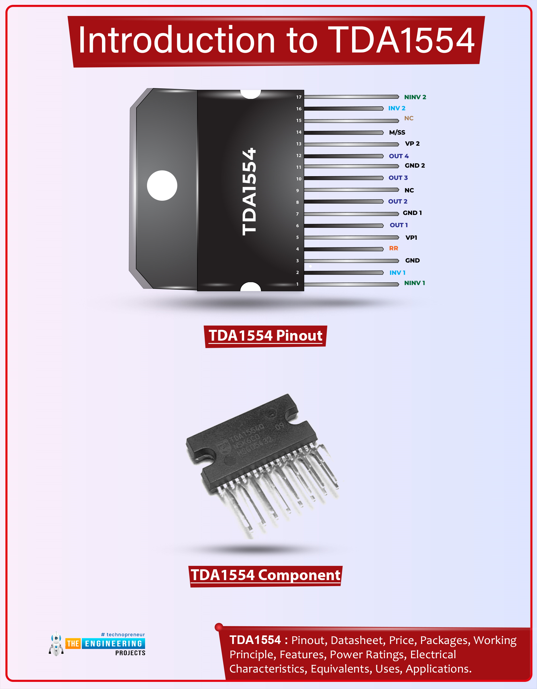
Hi Guys! Hope you’re well today. I welcome you on board. In this post today, I’ll walk you through the Introduction to TDA1554.

The TDA1554Q is an integrated class-B output amplifier mainly used for car radio applications. This device features 4 x 11 W single-ended or 2 x 22 W bridge amplifiers. It comes in a 17-lead single-in-line (SIL) plastic power package.

I suggest you buckle up and read this entire post till the end as I’ll discuss the complete Introduction to TDA1554 covering datasheet, pinout, features, and applications. Let’s get started.

Introduction to TDA1554

  • TDA1554 is a 4*11W single-ended or 2*22W power amplifier IC which means the internal circuitry features a 4*11W single-ended or 2*22W bridge amplifier.
  • It is an integrated class-B output amplifier that comes in a 17-lead single-in-line (SIL) plastic power package mainly used for car radio applications.

  • Out of four amplifiers incorporated in the device, two are non-inverting and two are inverting amplifiers.
  • Moreover, each amplifier comes with a gain of 20dB (26dB in BTL).
  • These amplifiers carry low thermal resistance and are thermally protected.
  • This device generates high output power and fixed gain.
  • Plus, a mute or standby switch is incorporated with the device helping you mute the amplifiers anytime you want.
  • This device can handle high energy on outputs and low voltage offsets at outputs and comes with good ripple rejection.

TDA1554 Datasheet

Before you apply this device to your electrical project, it’s better to scan through the datasheet of the component that features the main characteristics of the component. You can download the datasheet of TDA1554 by clicking the link below.

TDA1554 Pinout

The following figure shows the pinout diagram of TDA1554. The following table represents the pin configuration of each pin incorporated on TDA1554.
Pin Description of TDA1554
Pin No. Pin Description Pin Name
1 Non-inverting input 1 NINV1
2 Inverting input 1 INV1
3 Ground (signal) GND
4 Supply voltage ripple rejection RR
5 Positive Input Voltage 1 VP1
6 Output 1 OUT1
7 Power Ground 1 GND1
8 Output 2 OUT2
9 Not connected NC
10 Output 3 OUT3
11 Power Ground 2 GND2
12 Output 4 OUT4
13 Positive Input voltage 2 VP2
14 Mute/Stand-by switch M/SS
15 Not connected NC
16 Inverting input 2 INV2
17 Non-inverting input 2 NINV2

TDA1554 Features

  • Needs a few external components
  • Mute/standby switch
  • Remarkable ripple rejection
  • High output power and fixed gain
  • Flexibility in use - Quad single-ended or stereo BTL
  • Can handle high energy on outputs (VP = 0 V)
  • DC and AC short-circuit-safe to ground and VP
  • Low offset voltage at outputs (important for BTL)
  • Identical inputs (inverting and non-inverting)
  • Protected with Electrostatic Discharge, Load Dump, and Reverse Polarity
  • Low thermal resistance
  • Thermal protection

TDA1554 Power Ratings

  • Output Current = 4A
  • DC output offset voltage = 100mV
  • Supply Voltage Range = 6V to 18V
  • Input Impedance range = 50k? to75k?
  • Total Quiescent Current = 160mA
  • Stand-by Current = 10uA
  • Supply Voltage Rejection Ratio = 48dB

TDA1554 Applications

This component is mainly designed for car radio applications.

That’s for today. I hope you’ve enjoyed reading this article. If you have any questions, you can approach me in the section below. I’d love to help you according to the best of my expertise. Feel free to share your valuable feedback and suggestions around the content we share so we keep producing quality content tailored to your exact needs and requirements. Thank you for reading the article.

Syed Zain Nasir

I am Syed Zain Nasir, the founder of <a href=https://www.TheEngineeringProjects.com/>The Engineering Projects</a> (TEP). I am a programmer since 2009 before that I just search things, make small projects and now I am sharing my knowledge through this platform.I also work as a freelancer and did many projects related to programming and electrical circuitry. <a href=https://plus.google.com/+SyedZainNasir/>My Google Profile+</a>

Share
Published by
Syed Zain Nasir