Sending Email with ESP32 using SMTP Protocol

Hello readers, I hope you all are doing great. In this tutorial, we will learn how to send an email using ESP32 module. We will also learn to send text files, images or some sensor readings using the SMTP server using the ESP32 module.

In IoT (Internet of things), there are various applications where we need to send emails carrying information like sending some sensor readings, altering emails, images, text files and much more.

Where To Buy?
No.ComponentsDistributorLink To Buy
1ESP32AmazonBuy Now

What is SMTP?

SMTP or simple mail transfer protocol is an internet standard for sending and receiving electronic mail (or email) where an SMTP server receives emails from the email client.

SMTP is also used for setting communication between servers.

Various email providers like Gmail, Hotmail, Yahoo, etc. have unique SMTP addresses and port numbers.

How does SMTP work?

SMTP protocol which is also known as a push protocol is used to send emails and IMAP that is Internet Message Access Protocol (or post office protocol or POP) is used to receive emails at the receiver end.

SMTP protocol operates at the application layer of TCP/IP protocol.

When a client wants to send emails, a TCP connection will be open for the SMTP server and emails will be sent across the connection.

SMTP commands:

  • HELO – This command is sent only once per session and is used to identify the qualified domain names and the client to the server.
  • MAIL – used to initiate a message
  • RCPT – Identifies the address
  • DATA – share the data line by line

SMTP parameters for different email providers

SMTP parameters for Gmail

Gmail is the email service provided by Google and Gmail SMTP server is free to access and anyone can access this service, who has a Gmail account.

  • SMTP server: smtp.gmail.com
  • SMTP Port: 465
  • SMTP sender’s address: Gmail address
  • SMTP sender's password: Gmail Password

SMTP parameters for Yahoo

  • SMTP server: smtp.mail.yahoo.com
  • SMTP Port: 465 (with SSL)
  • Another Port number: 587 (with TLS)
  • SMTP sender’s address: email address
  • SMTP sender’s password: password

SMTP parameters for Hotmail

  • SMTP server: smtp-mail.outlook.com
  • SMTP port: 587
  • SMTP sender’s address: Hotmail email address
  • SMTP sender’s password: Hotmail password
  • SMTP TLS/SSL required : YES

SMTP parameters for Outlook

  • SMTP server: smtp-mail.office.com
  • SMTP server port for incoming mail: 993
  • SMTP server port for outgoing mail: 587
  • SMTP sender’s address: Outlook email address
  • SMTP sender’s password: Outlook password
  • SMTP TLS/SSL required : YES

Sending emails over SMTP using ESP32 in Arduino IDE

  • In this tutorial, we will demonstrate sending raw text messages and HTML messages, images, text files, etc. to the client over the SMTP server.

Components required to send and receive emails using ESP32 over SMTP server are:

  • Recipient’s email address.
  • Sender’s email address.
  • Content to be shared over SMTP server.
  • ESP mail client library.
  • ESP32 module.

ESP mail client Library

To send emails with ESP32 we need to install this ESP Mail Client library. This library, make ESP32 able to send emails over an SMTP server.

Step to install ESP Mail Client Library:

  • To download the ESP Mail Client Library click on the link given below: https://github.com/mobizt/ESP-Mail-Client
  • Open the Arduino IDE.
  • Go to Sketch >> Include Library >> Add .ZIP Library.
  • Select the downloaded ZIP file. Click on

Your Arduino IDE is ready to send email using ESP32.

Create a new Gmail account (Sender)

It is recommended to create a new email account for sending emails using ESP32 or ESP8266 modules.

If you are using your main (personal) email account (for sending emails) with ESP and by mistake, something goes wrong in the ESP code or programming part, your email service provider can ban or disable your main (personal) email account.

In this tutorial, we are using a Gmail account.

Follow the link to create a new Gmail account: https://accounts.google.com


Access to Less Secure apps

To get access to this new Gmail account, you need to enable Allow less secure apps and this will make you able to send emails. The link is: https://myaccount.google.com/lesssecureapps?pli=1

Arduino IDE Code, for sharing raw text and HTML text with ESP32 and SMTP server:
  • As we mentioned earlier, we are using Arduino IDE as a compiler and upload into the ESP32 module. To know more about Arduino IDE and how to use it, follow our previous tutorial Introduction to ESP32 Programming Series.
  • We have already discussed installing the ESP Mail Client Library to make ESP32 able to send emails over the SMTP server.
  • This library includes multiple examples on SMTP like sending text messages, images, HTML code, text files etc. We have attached an image below for your reference.
  • You can use those examples to send emails.

Fig SMTP example code

  • Note: You can not use the exact code. Hence, you need to make some changes like replacing SSID and password with your network credentials, email address of sender and receiver, SMTP setting parameters for respective email service providers etc, which need to be done before uploading the code. We will also describe these things during code description.

#include <WiFi.h>

#include <ESP_Mail_Client.h>

#define WIFI_SSID "SSID"

#define WIFI_PASSWORD "PASSWORD"

#define SMTP_HOST "smtp.gmail.com"

#define SMTP_PORT 465

/* The sign in credentials */

#define AUTHOR_EMAIL "email address"

#define AUTHOR_PASSWORD "email password"

/* Recipient's email*/

#define RECIPIENT_EMAIL "email address_Rx"

/* The SMTP Session object used for Email sending */

SMTPSession smtp;

/* Callback function to get the Email sending status */

void smtpCallback(SMTP_Status status);

void setup(){ Serial.begin(115200);

Serial.println();

Serial.print("Connecting to AP");

WiFi.begin(WIFI_SSID, WIFI_PASSWORD);

while (WiFi.status() != WL_CONNECTED){

Serial.print(".");

delay(200);

}

Serial.println("");

Serial.println("WiFi connected.");

Serial.println("IP address: ");

Serial.println(WiFi.localIP());

Serial.println();

/** Enable the debug via Serial port

none debug or 0 basic debug or 1

*/

smtp.debug(1);

/* Set the callback function to get the sending results */

smtp.callback(smtpCallback);

/* Declare the session config data */

ESP_Mail_Session session;

/* Set the session config */

session.server.host_name = SMTP_HOST; session.server.port = SMTP_PORT; session.login.email = AUTHOR_EMAIL; session.login.password = AUTHOR_PASSWORD;

session.login.user_domain = "";

/* Declare the message class */

SMTP_Message message; message.sender.name = "ESP32"; message.sender.email = AUTHOR_EMAIL; message.subject = "ESP32 Test Email";

message.addRecipient("Sara", RECIPIENT_EMAIL);

/*Send HTML message*/

String htmlMsg = "<div style=\"color:#2f4468;\"><h1>Hello CLient!</h1><p>- Sent from ESP board</p></div>"; message.html.content = htmlMsg.c_str(); message.html.content = htmlMsg.c_str(); message.text.charSet = "us-ascii";

message.html.transfer_encoding = Content_Transfer_Encoding::enc_7bit;

//Send raw text message

/* String textMsg = "Hello Client! - you have a message from ESP32 board"; message.text.content = textMsg.c_str(); message.text.charSet = "us-ascii";

message.text.transfer_encoding = Content_Transfer_Encoding::enc_7bit;*/

message.priority = esp_mail_smtp_priority::esp_mail_smtp_priority_low;

message.response.notify = esp_mail_smtp_notify_success | esp_mail_smtp_notify_failure | esp_mail_smtp_notify_delay;

/* Set the custom message header */

//message.addHeader("Message-ID: <abcde.fghij@gmail.com>");

/* Connect to server with the session config */ if (!smtp.connect(&session))

return;

/* Start sending Email and close the session */ if (!MailClient.sendMail(&smtp, &message))

Serial.println("Error sending Email, " + smtp.errorReason());

}

void loop(){

}

/* Callback function to get the Email sending status */

void smtpCallback(SMTP_Status status){

/* Print the current status */

Serial.println(status.info());

/* Print the sending result */ if (status.success()){

Serial.println("----------------");

ESP_MAIL_PRINTF("Message sent success: %d\n", status.completedCount());

ESP_MAIL_PRINTF("Message sent failled: %d\n", status.failedCount());

Serial.println("----------------\n"); struct tm dt;

for (size_t i = 0; i < smtp.sendingResult.size(); i++){

/* Get the result item */

SMTP_Result result = smtp.sendingResult.getItem(i);

time_t ts = (time_t)result.timestamp; localtime_r(&ts, &dt);

ESP_MAIL_PRINTF("Message No: %d\n", i + 1);

ESP_MAIL_PRINTF("Status: %s\n", result.completed ? "success" : "failed"); ESP_MAIL_PRINTF("Date/Time: %d/%d/%d %d:%d:%d\n", dt.tm_year + 1900,

dt.tm_mon + 1, dt.tm_mday, dt.tm_hour, dt.tm_min, dt.tm_sec); ESP_MAIL_PRINTF("Recipient: %s\n", result.recipients); ESP_MAIL_PRINTF("Subject: %s\n", result.subject);

}

Serial.println("----------------\n");

}

}

Code Description

  • The first task is adding the required header files or libraries.
  • Wifi.h is used to enable the Wi-Fi module and hence wireless network connectivity.
  • Another library is ESP_Mail_Client.h to enable email service over SMTP (simple mail transfer protocol).
  • Enter the network credentials in place of SSID and PASSWORD.
  • Insert SMTP parameter of the respective email service provider.
  • The parameters used below are for Gmail.
  • Enter the sender’s email address and password details.
  • Insert recipient’s email address.
  • SMTPSession object is used for sending emails.
  • This smtpCallback() function is used to get the email sending status.
  • This function also includes printing the results like success and failure of email sent.

Setup()

  • Initialize the serial monitor at a 115200 baud rate for debugging purposes.
  • WiFi.begin() function is used to initialize the Wi-Fi module with Wi-Fi credentials used as arguments.
  • The While loop will continuously run until the ESP32 is connected to the Wi-Fi network.

  • If the device is connected to a local Wi-Fi network then print the details on the serial monitor.
  • WiFi.localIP() function is used to fetch the IP address.
  • Print the IP address on the serial monitor using Serial.println() function.

  • Serial.debug() is used to enable the debug via Serial port where ‘0’ and ‘1’ are used as arguments where;
    • - none debug
    • - basic debug
  • Inside ESP_Mail_FS.h header file, ESP_MAIL_DEFAULT_DEBUG_PORT can be used to change the Debug port.
  • Set the smtp.callback() function to get sending results.

  • Next step is setting the message header.
  • Message header will be set inside the setup() function which includes, sender’s name, subject, sender’s email address, receiver’s email address and name.

Sending raw text message

Write the message content (raw text) in the textMsg variable which you want to share over email.

Sending HTML text

To send HTML text write the respective content in the htmlMsg variable.

  • Connect to server with session configuration using smtp.connect() function.
  • Next thing to do is, send an email to the client for that MailClient.sendMail() function is used and if mail transmission is failed then that will be printed on the serial monitor along with the reason.
  • Loop() function will remain empty.

Testing

  • Upload the Arduino IDE code in the ESP32 module.
  • Make sure the Wi-Fi network is ON to which your ESP32’s Wi-Fi module is supposed to connect.
  • Open Serial monitor with 115200 baud rate.
  • Also, make sure that you have turned ON the permission for less secure apps.

Otherwise, you won’t be able to send emails and an error will be printed on the serial monitor.

  • Press the EN button from the ESP32 development board.

  • Check receiver email inbox.

Arduino IDE code, for sending images and text files using ESP32 and SMTP server:

In this example code, we will demonstrate how to share text files and images through emails using ESP32 over the SMTP server.

But, before sharing attachments (text files or images) you need to save those files on the ESP32 filesystem (SPIFFS).

Uploading files to ESP32 Filesystem (SPIFFS)

SPIFFS stands for Serial Peripheral Interface Flash File System, which is built into the ESP32 module. This is a lightweight filesystem designed for microcontrollers with flash chips connected via SPI bus, such as the ESP32 flash memory. In this flash memory, we can write, delete, read, and close files.

  • Text files and images will be saved on ESP32 filesystem (SPIFFS) using ESP32 filesystem uploader plugin for Arduino IDE.

Installing Arduino ESP32 Filesystem Uploader:

Fig.

  • Restart the Arduino IDE.

Check if the plugin is successfully uploaded or not:

  • Open Arduino IDE. Select ESP32 development board.
  • Go to
  • Check whether this ESP32 Sketch Data Upload option is available or not. If it is available that means plugin is uploaded successfully and it is ready to upload files.

Fig.

Finally, uploading files using SPIFFS or filesystem upload:

  • In Arduino IDE, create a new Arduino sketch.
  • Save the project.
  • Go to Sketch >> Show Sketch Folder. As shown in the image below:

Fig.

  • Create a new folder named as

Fig.

  • Inside that data folder add the respective text files or images you want to share over email as shown in the image below:

Fig.

  • If you are using the example code from ESP mail-client library then the images should be named as png and text files as text_file.text.
  • After saving files inside data folder, open the Arduino IDE then go to Tools >> ESP32 Sketch Data Upload to upload the SPIFFS Image.

Fig.

A message “SPIFFS Image Uploaded” will be displayed at the bottom of Arduino IDE, once the SPIFFS image is uploaded successfully.

Fig.

Arduino IDE Code

Code is already available in ESP Mail Client Library. As shown below:

Fig.

  • You can not use the exact code.
  • Some changes like Wi-Fi credentials, email address of sender and receiver, SMTP setting parameters for respective email service providers etc, need to be done before uploading the code.

// To use send Email for Gmail to port 465 (SSL), less secure app option should be enabled. https://myaccount.google.com/lesssecureapps?pli=1

// The file systems for flash and sd memory can be changed in ESP_Mail_FS.h.

#include <Arduino.h>

#include <WiFi.h>

#include <ESP_Mail_Client.h>

#define WIFI_SSID "SSID"

#define WIFI_PASSWORD "PASSWORD"

// server address for Gmail account

#define SMTP_HOST "smtp.gmail.com"

/** The smtp port e.g.

25 or esp_mail_smtp_port_25 465 or esp_mail_smtp_port_465 587 or esp_mail_smtp_port_587

*/

#define SMTP_PORT 465

/* The log in credentials */

#define AUTHOR_EMAIL "Sender's email address"

#define AUTHOR_PASSWORD "password"

/* Recipient's email*/

#define RECIPIENT_EMAIL "receiver's email address"

/* The SMTP Session object used for Email sending */

SMTPSession smtp;

/* Callback function to get the Email sending status */

void smtpCallback(SMTP_Status status);

void setup(){

Serial.begin(115200);

Serial.println();

Serial.print("Connecting to AP");

WiFi.begin(WIFI_SSID, WIFI_PASSWORD);

while (WiFi.status() != WL_CONNECTED){

Serial.print(".");

delay(200);

}

Serial.println("");

Serial.println("WiFi connected.");

Serial.println("IP address: ");

Serial.println(WiFi.localIP());

Serial.println();

if (!SPIFFS.begin(true)) {

Serial.println("An error has occurred while mounting SPIFFS");

}

else{

Serial.println("SPIFFS mounted successfully");

}

/** Enable the debug via Serial port

  • none debug or 0
  • basic debug or 1

*/

smtp.debug(1);

/* Set the callback function to get the sending results */

smtp.callback(smtpCallback);

/* Declare the session config data */

ESP_Mail_Session session;

/* Set the session config */ session.server.host_name = SMTP_HOST; session.server.port = SMTP_PORT; session.login.email = AUTHOR_EMAIL; session.login.password = AUTHOR_PASSWORD;

session.login.user_domain = "mydomain.net";

/* Declare the message class */

SMTP_Message message;

/* Enable the chunked data transfer with pipelining for large message if server supported

*/

message.enable.chunking = true;

/* Set the message headers */ message.sender.name = "ESP Mail";

message.sender.email = AUTHOR_EMAIL;

message.subject = "Test sending Email with attachments and inline images from SD card and Flash";

message.addRecipient("Sara", RECIPIENT_EMAIL);

/** Two alternative content versions are sending in this example e.g. plain text and html */

String htmlMsg = "This message contains attachments: image and text file."; message.html.content = htmlMsg.c_str(); message.html.charSet = "utf-8";

message.html.transfer_encoding = Content_Transfer_Encoding::enc_qp;

message.priority = esp_mail_smtp_priority::esp_mail_smtp_priority_normal; message.response.notify = esp_mail_smtp_notify_success | esp_mail_smtp_notify_failure | esp_mail_smtp_notify_delay;

/* The attachment data item */

SMTP_Attachment att;

/** Set the attachment info e.g.

  • file name, MIME type, file path, file storage type,
  • transfer encoding and content encoding

*/

att.descr.filename = "image.png"; att.descr.mime = "image/png"; //binary data

att.file.path = "/image.png";

att.file.storage_type = esp_mail_file_storage_type_flash;

att.descr.transfer_encoding = Content_Transfer_Encoding::enc_base64;

/* Add attachment to the message */

message.addAttachment(att);

message.resetAttachItem(att);

att.descr.filename = "text_file.txt"; att.descr.mime = "text/plain"; att.file.path = "/text_file.txt";

att.file.storage_type = esp_mail_file_storage_type_flash;

att.descr.transfer_encoding = Content_Transfer_Encoding::enc_base64;

/* Add attachment to the message */

message.addAttachment(att);

/* Connect to server with the session config */ if (!smtp.connect(&session))

return;

/* Start sending the Email and close the session */ if (!MailClient.sendMail(&smtp, &message, true))

Serial.println("Error sending Email, " + smtp.errorReason());

}

void loop()

{

}

/* Callback function to get the Email sending status */

void smtpCallback(SMTP_Status status){

/* Print the current status */

Serial.println(status.info());

/* Print the sending result */ if (status.success()){

Serial.println("----------------");

ESP_MAIL_PRINTF("Message sent success: %d\n", status.completedCount());

ESP_MAIL_PRINTF("Message sent failled: %d\n", status.failedCount());

Serial.println("----------------\n"); struct tm dt;

for (size_t i = 0; i < smtp.sendingResult.size(); i++){

/* Get the result item */

SMTP_Result result = smtp.sendingResult.getItem(i); time_t ts = (time_t)result.timestamp;

localtime_r(&ts, &dt);

ESP_MAIL_PRINTF("Message No: %d\n", i + 1);

ESP_MAIL_PRINTF("Status: %s\n", result.completed ? "success" : "failed"); ESP_MAIL_PRINTF("Date/Time: %d/%d/%d %d:%d:%d\n", dt.tm_year + 1900,

dt.tm_mon + 1, dt.tm_mday, dt.tm_hour, dt.tm_min, dt.tm_sec);

ESP_MAIL_PRINTF("Recipient: %s\n", result.recipients);

ESP_MAIL_PRINTF("Subject: %s\n", result.subject);

}

Serial.println("----------------\n");

}

}

Code Description:

Most part of the code is similar to the previous one (that is sending raw text and HTML text), including libraries, network credentials, enabling Wi-Fi and the serial monitor, setting the email parameters of the respective email service provided. So we not explaining the complete code but, we will explain the programming part which is different than the previous one.

Setup()

  • We are initializing the SPIFFS, inside the setup() function to sore files which are to be shared over the SMTP server.
  • begin() function is used to for initializing SPIFFS.

Fig.

  • If the server supports, enable chunked data transfer with pipelining for large messages.

Fig.

  • Next, you need to create data attachments.

Fig.

  • The next thing is sending the image, for that you need to add the attachment details: filename, path, mime type, type of storage, encoding technique.
 

Fig.

  • After adding the details of the image, add the attachment to the message.

Fig.

  • To send a text file you also need to add similar details: name of the file, path, storage type, mime type and encoding technique.

Fig.

  • Add this attachment too to the message.

Testing

  • Upload the code into the ESP32 board.
  • Make sure you have selected the correct ESP32 development board and COM port.
  • Also, make sure that you have turned on the access for less secure apps for the sender’s email account as discussed earlier. Otherwise, the ESP32 will face an authentication error.
  • Turn ON the Wi-Fi with which your device is supposed to connect with.
  • Once the device is connected with the access point, it will automatically send the attachment to the receiver's email account.

Fig.

Fig.

Fig. Email Received

This concludes the tutorial; I hope you found this helpful and also hope to see you again with a new tutorial on ESP32.

How to use Counters in Ladder Logic Programming?

Hello friends! We hope you are very well! Today we are here for complementing our knowledge with one of the most important topics in PLC programming and practice its implementation in PLC ladder logic programming. Our topic today is about counters which help us to know the production size at any time, the repetition of specific tasks and events. Many real-life situation problems need counter like garage capacity should be tracked by using counters to report how many cars are inside and if there is room for incoming cars or it's full. Another critical problem is to count the repetitive tasks and events in manufacturing. Furthermore, counting products and pieces for taking an action like performing maintenance, stop operation, turn over to next production stage... et cetera.

Counter in conventional control

Counters are used in conventional or relay logic control. they mainly receive pulses and count these pulses and when it reaches a preset value the output coil of the counter is energized. They mostly include an LCD showing the counting as shown in figure 1.

Figure 1: Omron counter [1]

The main idea of most counters is counting input pulses by using logic circuits i.e. flip-flop and determining the output based on which an output relay is energized. There are two main types of the counter as regards structure: synchronous counters when all flip-flops and asynchronous counters when each flip-flop is connected to its separate clock. In addition, counters can be classified based on functionality into UP, DOWN, and UP-DOWN counters. If you are not familiar with logic circuit components like flip-flops so do not worry as it's not our concern here. We just want to let you know how physical counters in the traditional controller are complicated and take a lot of space as we need hundreds of flip-flops and other circuit components to have a counter which counts for a limited number. Figure 2 shows the logic circuit of the counter that can count from 0 to 9. It utilizes 4 flip-flops as shown. The type of this counter is an asynchronous counter as each flip-flop takes its clock from the output of the previous flip-flop. Furthermore, table 1 lists the truth table of the counter. It shows how the counter determines the count based on the output Q0, Q1, Q3, and Q4. For example, when all outputs are zeroes, that means the counter reads zero. When Q0 is high, Q1 is low, Q2 is low, and Q3 is high, that means the counter reads 9. But in PLC, it's the easier story, it’s software counters with flexible functionality and usability as well as we will see in the next section. So let's enjoy learning and practicing counters in ladder logic programming.

Figure 2: Asynchronous 0-9 counter

Table 1: the truth table of 0-9 counter

Pulse to be counted Q3 Q2 Q1 Q0
0 0 0 0 0
1 0 0 0 1
2 0 0 1 0
3 0 0 1 1
4 0 1 0 0
5 0 1 0 1
6 0 1 1 0
7 0 1 1 1
8 1 0 0 0
9 1 0 0 1
 

Counter in PLC

Simply, Counter in plc is an instruction to count up or down to preset value and energize an output at reaching that preset value. There are three types of counters in PLC which are:

Count up type

In this counter, each time a trigger input signal has been received at (CU), the counter counts up until reaching the preset value (PV) to energize output as shown in figure 3. The counter has three inputs: the trigger command, the reload command, and the preset value to set to what number the maximum counter is going to count up. Furthermore, it has two outputs: the counter output which is turned to true when the counter reaches the PV values, and the current value (CV) which tells the current value at any time to whom the counter reaches.

Figure 3: The counter Up instruction block [2]

Count down type

In this counter, each time a trigger input signal has been received at (CD), the counter counts down until it reaches zero at then the counter output is energized. As shown in figure 4, the counter has three inputs: the trigger command for counting down (CD), the reload command to reload to the PV value, and the preset value to set to what number the initial value from whom the counter starts the count down. Furthermore, it has two outputs: the counter output which is turned to true when the counter reaches the PV values, and the current value (CV) which tells the current value at any time to whom the counter reaches.

Figure 4: The counter down instruction block[2]

Up-Down counters

In this counter, the two functions of the count up and count down can be combined in one block. each rising edge of a trigger input signal has been received at (CD), the counter counts down. And each time it receives a command trigger signal at (CU), it counts up and so on till it reaches the PV values. At then the counter output is energized. As shown in figure 5, the counter has five inputs: the trigger command for counting down (CD), the trigger command for count up (CU), the reload command to reload to the PV value, the reset command to reset to zero, and the preset value to set to what number the initial value from whom the counter starts counting up or down. Furthermore, it has three outputs: the counter down output (QD) which is turned to true when the counter reaches zero, the counter up output (QU) which goes to true when the counter reaches the PV value, and the current value (CV) which tells the current value at any time to whom the counter reaches.

Figure 5: The counter Up-down instruction block[2]

Ladder program examples for counters

Now after we have introduced to counters in PLC as regard to their types, functionalities, inputs, and outputs, let’s get to have the fun of practicing our lab work for counters with our simulator.

Count up example

Figure 6 shows the ladder simple program example for a counter of type Up counter. In this example, the counter counts the input objects by a sensor that triggers the counter to increment. The ladder program is shown on the left side window while the simulator window appears on the right part. You can notice on the simulator window, we track all inputs and outputs as well. In the beginning, the current value (CV) is zero and the preset value is set to 10 meaning the counter will energize its output when it counts up to 10. Let’s press the input trigger and see what is going on. My friends, try to think before you go forward to see the simulator output as I am ganging will be the same as what you imagine!

Figure 6: Ladder example of a counter UP type

As you imagine exactly, figure 7 shows the counter is incrementing each time the input trigger signal is rising. Until it reach to or above 10 which is the PV value at then the counter output turns on as shown in figure 8.

Figure 7: The counter incrementing with triggering signal input

Figure 8: the counter output turns ON by reaching to or above the PV value

On the other hand, the reset signal can be used for resetting the counter to the zero to start over counting as shown in Figure 9.

Figure 9: the counter CV reset to zero by hitting the reset.

Count down example

This counter is used to count down from the PV value to zero. Figure 10 shows a very simple ladder program for the count down the program on the left part and its simulation appears on the right as well. The simulation windows show the PV value is set to 10 and the current value (CV) is initially starting from the PV value. Therefore, it starts with a value of 10. So let’s try to hit the input CD signal and see what the simulator shows.


Figure 10: Ladder example of count down counter

Figure 11 shows the counter is decrementing the CV by hitting the input CD. And continue decrementing until reaching zero. So what is going to happen then? Think!

Figure 11: the counter is decrementing by hitting the input CD

Exactly! And well though, as figure 12 shows, once the counter reaches zero, the output changes to true.

Figure 11: the counter output set to TRUE when reaching zero

Again, the reset button can be utilized to reset the counter to its initial state as shown in figure 12. You can notice that the CV reset to 10 which is the initial value and equal to the preset value (PV).

Figure 12: Reset button reinitiate the counter to the PV value

Count up-down example

Now we are going to combine all features in the UP and down counters in one counter which is called the UP-Down counter. Figure 13 shows a simple ladder example for that counter. The ladder code is shown on the left and the simulator window is on the right. The simulation window shows all inputs and outputs of the UP-DOWN counter.

Figure 13: A ladder example of UP-Down counter

Testing the up-down counter ladder program

We have two functions to test with this type of counter which is up counting and down counting. Figure 14 shows the initial state of the ladder program, it shows we start testing when the current value (CV) shows 2. So what do you expect when hitting the count up and the count down? Thinking and validate with the simulator results below.

Figure 14: initial state at the running of the up-down example

By hitting the count-up function, the counter acts like a UP counter and the current value is incremented as in figure 15.

Figure 15: count up function incremented the CV

On the other hand, by hitting the count down function, the counter acts as a down counter and the current value is decremented as in figure 16. And by pressing reset, the counter CV value will be reset to zero, while it reloaded to the PV value by pressing the load counter button. In addition, the output QU will be energized when the counter reaches or is higher than the PV value which is 10 in this example while the output QD will be true when the counter reaches zero. To sum up, this up-down counter can act as both types of counters UP and Down. I know someone is going to ask why we have such a counter when we already have one of each counter type? Well! That’s a really good question. And the answer is that, yes we can implement any problem relating to performing counting by using these two counters. However, some problems need to perform both functions UP and Down counting at the same time. For example, the Garage problem has cars getting in and out all the time and when cars get in we need to count up the cars and when cars get out we need to count down to report the number of cars in the garage at any time. So in such a problem, having one counter do the whole job is better than having two punters for reducing the conflictions and increasing the flexibility of calculations.

Figure 16: count down function decremented the CV

Next topic

I would like to thank you so much for following up with us up to this point of learning and practice. Despite briefly introducing the logic gates, we will elaborate in the next station on the logic gates and their functions and usage in ladder logic programming. So you be ready for more learning and practice the ladder logic and logic gates in deep detail.

How to Use Timers in Ladder Logic Programming?

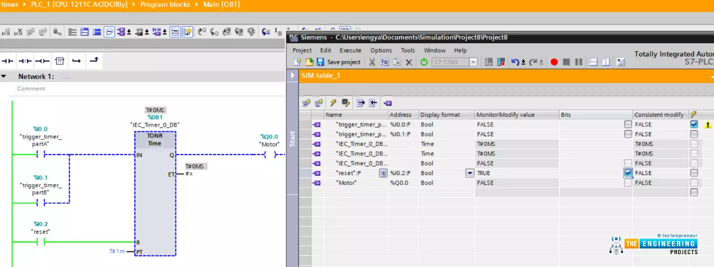
Hello friends! I hope you are doing very well, today we have a very crucial topic which is “timers”. Yes! Exactly like what comes to your mind. For running equipment i.e. motor at a specific time and/or for some amount of time we need timers. Timers are used even before PLC in classic or relay logic conventional control. However, there is a big difference between capabilities and limitations between using physical timers in classic or old fashion relay logic and using software timers in PLC. By completing this article you will be able to know what are timers and their types and applications. In addition, we are going to show off how to use timers in ladder logic programming with examples.

What are timers used for in industrial applications?

Well! This is a very good question to start and its answer can be taken as a motive to learn timers comprehensively. Timers are used to turn on actuators i.e. motors for a specific amount of time or turn off them after a specific amount of time. They are used for scheduling tasks on and off based on the process sequences.

How do timers work?

There are many types of timers based on the functions. However, all timers are working in the same principle that they are preset to a specific amount of time. Then when their coils are energized, the timers’ contacts are changing over to the opposite of their initial states i.e. from ON to OFF or from OFF to ON based on the delay time and the timer type. Therefore, we can imagine the main components of timers are the coil and contacts as shown in figure 1 [1]. It shows a relay timer for Telemecanique type showing the setting for the time delays, coil, and the contacts.

Figure 1: physical relay timer

Advantages of Timers in PLC over relay timers

The relay timers are limited in time setting i.e. for 24 hours and a specific amount of physical NO and NC contacts. While timers in PLC are logical software components with the unlimited setting of time which makes them very flexible with logic requirements. In addition, using physical relay timers costs us more space and wiring. While we can use soft timers in ladder logic with no limitations. Types of timers as we are going to describe in detail later, are limited to basic functions in the relay timers while all types of timers can be implemented in PLC using ladder logic programming.

Timers types

All timers have a coil and contacts and the latter will be changed over their states by energizing their coil based on the preset time and the type of timer. In the following subsection the most common timer types are introduced:

ON-DELAY timer

This type of timer is used to postpone the start of running. Figure 2 depicts the timing diagram of the On-Delay timer. As shown in this timer delayed the output from the input by the preset delay time. The figure shows that, after the input gets started, the time counts up until the preset amount of time elapsed, then the output starts as long as the input is ON. However, in the second pulse of the input, we can notice the output was not started because there was no chance to reach the amount of delay time that is preset in designing the timer.

Figure 2: The timing diagram of the On delay timer [2]

OFF-DELAY timer

In this type of timer, we aim at delaying the shutdown of the output. Figure 3 depicts the timing diagram of the OFF delay timer in which, the output starts at the time input starts and the output lasts after a specific time delay after the input gets off. You can notice that, in the second pulse of the input, the output did not shut down after the second pulse of the input due to the incoming of another input pulse before the delay time reached the preset value.

Figure 3: The timing diagram of the Off delay timer [2]

Pulse timer

This timer type energizes the output in each rising edge of the input for a fixed amount of time. Figure 4 shows the timing diagram of a pulse-type timer. It shows the output comes active each time it finds a rising edge of the input and keeps active for a fixed amount of time which is preset for the timer.

Figure 4: Timing diagram of, the pulse timer [2]


Accumulative timer

In an on-delay timer, if the input does not stay on for the preset time delay period there would not be a chance for the output to be energized. So there should be another modified timer to accumulate the period each time the input is ON and activate the output when reaching the preset value. This timer is called an accumulative timer and its timing diagram is depicted in figure 5. In this example, assume the preset values of 12 s, the first input pulse shown in blue resumes for 4 seconds and it goes on for another 8 seconds. The time is accumulated from the first and the second pulse until reached the preset value which is 12 seconds. The output gets ON as long as the preset time has reached and the input is ON.

Figure 5: on-delay accumulative timer

Timers in PLC and ladder logic program

Timers of different types can be used in PLC with great flexibility. Now let’s learn and practice timers with our simulator. But before we get to start we just need to introduce ourselves to the timer blocks in the ladder logic program.

Generate ON delay timer instruction

Figure 6 shows the instruction for generating an ON Delay timer. As you can see the instruction has two inputs and two outputs. The first input “IN” is the input contact of type Boolean. This input contact triggers the timer and initiates it to start counting the time. The second operand is the “PT” by which we set the required time delay. Moving to the outputs, the first output is “Q” this is the main output of the timer and it turns to true when the timer reaches the preset time delay. The second output is the “ET” which reports the time elapsed so far since the timer started to count time. The “PT” and “ET” are of time data type format and can be in milliseconds, seconds, minutes, hours, days et cetera.

Figure 6: Generate ON delay instruction

ON-Delay timer example ladder program

Figure 7 shows a very simple example program that uses an ON Delay timer for delaying the running of a motor. The ladder code is shown on the right part of figure 7. It shows that one input contact connected to address “I0.0” and its tag named “trigger_timer” is connected to the timer input. And the preset value is set to be one minute “T#1m” which means one minute. Notice the format is very simple. You type T denoting the time format and then “#” followed by the amount of time and at last the unit of time which could be “MS” for milliseconds, “S” for seconds, “m” for minutes, “d” for days … et cetera. Moving to the outputs, the timer output “Q” is connected to the motor meaning that the motor will be running after the timer counts complete one minute. The other output is “ET” which tells the time elapsed so far since the timer set to start counting time. Let’s go to the simulator window on the left side. We added all inputs and outputs to control the inputs and show the output as well. You can notice that, by setting the input “trigger_timer” to true, the timer starts counting the time as you can read in the “ET” variable that shows the time spent so far “T#29S_335MS” meaning 29 seconds and 335 milliseconds have been elapsed since input set to true. Since the PT time is not reached, the output is still false as shown in blue color.

Figure 7: ON-Delay timer sample program with a simulator

Figure 8 shows the moment when the timer reached the PT value which is one minute in our example. You can notice on the left window, the ET value becomes one minute which is equal to the PT value. Therefore, the timer output turned to true and the motor is switched on consequently. To sum up, this example shows how the output has become ON after one minute delay of the input.

Figure 8: ON-Delay timer energized the output after one minute delay

OFF delay timer example ladder program

After we have shown how we can delay the start of a motor by using the On Delay timer. Here we are going to show how to delay the shutdown. Figure 9 shows an example of a very simple ladder program that uses an OFF delay timer to delay the shutdown of an output. As you can see on the left the input is ON and the output starts running with the input at the same time. Let's try to set the input OFF as in figure 10, you can notice the output is still ON and the time counter is incrementing until it reaches the PT value which is set to one minute in our example. Figure 11 reports the moment at which the time counter reached the PT value which is one minute. At that moment the output or the motor is shut down. In a conclusion, the Off delay timer is our tool to delay the shutdown of output or terminate a process.

Figure 9: OFF delay timer example

Figure 10: The input is off while input is still run

Figure 11: the output shutdown delayed one minute

Pulse timer example

In this example, we are going to start and stop the motor in a pulsative operation mode thanks to the pulse timer type. That means the input to the timer will start the output to run for a specific amount of time that is present in the PT value regardless of receiving any other input pulses. In figure 12, the pulse timer example is shown. The very simple ladder logic program is displayed on the left window and the simulation is shown on the left window. You can notice that, once the timer received a high state of the input, it energized the output and started counting the time. However, when the input went OFF the output keep running ON for the designated while represented in PT value which is one minute for this example as shown in figure 13. Let’s test the condition of having another input signal as shown in figure 14. When the input goes again high which the last pulse does not complete, the output continues running and the timer does not reset its timing count. However, when the pulse time is reached as in figure 15, the output is shut down and the timer now is ready to start another pulse by noticing a rising edge of the input.

Figure 12: pulse timer example

Figure 13: the output continue running for its pulse period

Figure 14: another pulse does not reset the timer until complete one pulse period

Figure 15: output shutdown after completing pulse period

Accumulative timer ladder example

In this ladder example, we are going to show you how to continue accumulating the time until reaching the PS value at which the timer energizes its output as shown in figure 16. The example shows a very simple ladder code that has two inputs connected in parallel to OR logic. So any of these two inputs will trigger the counter to count up the time. On the left window, all inputs and outputs including timer operand and outputs are listed in simulating table to show the values while the program is executing.

Figure 16: an accumulative timer ladder example program

Let us start triggering the timer by one of the inputs as shown in figure 17. As you can notice the timer starts counting the time as shown in the ET value on the left window showing the simulation. What if we set the inputs OFF? In the ON Delay timer, the time will be reset. But in this timer, it does not and instead, it waits for another input signal to accumulatively increment the time till reaching the PT value as shown in figure 18. Let’s verify the concept by setting one of the inputs ON as shown in figure 19, the timer accumulates the timing counter until it reached the PT value which is set to one minute in this example. At that moment the output is energized as shown in figure 20. And finally, figure 21 shows how the timer is reset by switching on a reset button. One good practical example for using this type of timer is the maintenance schedule. For example, we can schedule the maintenance to be conducted after one year or after a specific amount of time or number of operating hours. So the timer will keep accumulating the time of operation regardless of the downtime and raise a flag to notify it is the time for performing maintenance.

Figure 17: starting the timer by enabling one of the inputs

Figure 18: setting the inputs off does not reset the timer

Figure 19: timer accumulates the time

Figure 20: the output goes ON after reaching the PT value

Figure 21: timer reset its timing count

What next

I would like to thank you so much for following up with our tutorial that far. So far you are familiar with timers types and how to utilize the suitable one for your task based on the logic you want to perform. Next tutorial we are going to go through counters showing their types and functionalities and for what reasons we need counters how we can use them appropriately.

Latching in Ladder Logic Programming

Hi friends! I hope you are doing well! Today we are going to learn and practice a new topic which is a very crucial technique in plc programming. the topic is called “latching”. We mean by Latching to keep the output running starting from the instance of giving a kick-off command until we hit a command to stop running of the motor. Imagine my friends, operator wants to start a motor by hitting a start push button and want the motor to keep running and leave and go for doing another task or job. And then it keeps running until the operator wants to stop it. The problem here is that, once the operator releases his hand away from the push button, the motor automatically stopped and that is not like what the operator wants to do with the motor. To clear the problem that we are going to solve, and for which we need to use the latching technique to connect a load, Figure 1 has been created for you to show the situation to make a direct connection to a motor by using a simple push-button. In this circuit, the operator needs to keep pressing the push button as long as he needs the motor to keep working. Otherwise, the motor will stop once he releases the push button. So would please think with to figure out what is the solution for that?

Fig. 1: Connecting motor to power by push button directly

Let’s try to connect the motor through a relay as it is typically in the industry. Maybe that helps us to control the way to energize the relay coil and use its contacts to start and stop the motor, Figure 2 shows how we can employ a relay to connect the motor to the power source. However, again In fig. 2, the operator still has to keep pressing the button as long as he wants the motor to keep running. This is not the best practice in real life, the operator has many jobs to do. So, he wants to give the command to commence running the motor and leave it running to perform some other tasks and then has the motor stops after the job has been done. In this case, latching is the best practice to connect the motor or any load we want it to run for a while or until complete some functions.

Fig. 2: relaying motor to DC power by hitting start push button

How does latching work?

Now, I hope you can feel the problem between our hands and sense the meaning of the word “latching”. Again, in a real-life situation, motors or any actuators can be run via relay, by energizing the relay’s coil, the contacts of the relay switches over from off to on and then connects the motor to let it starts spinning. So for running the motor, the rely on coil should be energized. However, the latching technique makes that requirements go away, instead of that, the contact that has been used for connecting the motor to power, is used to be another pathway to connect the rely on the coil to power without needing to keep pressing the start push button. WoW! What amazing solution is that! to just hit a button and then forget about it and use the contact to make like a closed-loop to have the coil connected to power forever and let the motor work forever. Ohhh!! Forever!!! How do we run the motor without stopping? Yes, you are correct. It should be a way to break that loop when we want to do stop it. we need a way to just stop the latching, to break its loop, to enable the operator to stop the motor when they need to do.

Steps to perform latching

Let’s now show you guys how we can establish and construct a complete latching circuit step by step. In the following subsections, three steps by which will be demonstrating how to complete a typical latching circuit including only push-button and relay.

Latching Step one

First of all, in a very simple circuitry which is shown in Fig. 3, the DC power lines positive and negative are connected with a push-button and relay to run a load. The positive wire in red is connected to the push button and then to the coil terminal A1 and A2, and then to the ground black wire. So now, it’s clear that when the push button is pressed it turned on and connects the circuit of the relay coil all the way to be energized. As a result, the contact of the relay is connected and now it is ready to connect the external circuit to run an actuator i.e. motor. But when the push button is released, the coil will be de-energized and the relay coil turns back to the open state and the motor is going to stop. So moving to the next step of building a latching circuit in which we aim at creating another pathway to supply the relay coil with power to forget about the push button and have it continue to run even after releasing the push button.

Fig. 3: the typical push-button and relay circuit

Latching step two

Now Fig. 4 shows the main wiring schematic of a basic latching circuit by which we indeed realize the concept and functionality of the latching technique. in the circuit, you can notice my friends that, the contact upper point and the relay upper point are connected in such a way that, it creates another pathway for energizing the relay coil without any needs to press or even touch the push-button B1. Again, when the push button B1 is pressed, the relay coil will be energized. As a result, the relay contact will be close contacted and in turn bridges point A1 to the positive red wire. Now, when the push button is released, the relay coil still has another pathway to connect to the positive wire so the relay coil will keep energized. I know now what comes out to your mind? if this configuration and schematic can put the relay coil in the loop and energize all the time by the first kick-off by hitting the start button thanks to the latching technique. The question now is, how about stopping the motor?. How to break this loop? Yes, that’s the only thing is remaining to complete a typical latching circuit.

Fig. 4: the second step of latching

Latching step three

We can name this step by ending latching. As shown in fig. 5, a normally close (NC) push-button B2 is added in the way from contact to the positive, red, power wire. Firstly, when the push button B1 is pressed, the relay coil is energized. And the contact of the coil is connected to the positive red wire as the push-button B2 is in a closed state by default. So now, it will be latching as long as the connection to the positive wire does not break. So by hitting push-button B2, it will turn out to open state and the connection to the positive wire is broken. Therefore, the relay coil will be de-energized and the latching gets to stop.

Fig. 5: Ending latching step 3

Latching in ladder logic programming

I know guys you all are waiting to come to this point to go to our lab and simulator and practice our tutorial. So now after we discussed the concept and basics of what latching is and how does it work? We now are all set to start our simulator and practice latching techniques in ladder logic programming as we used to do every tutorial.

Ladder logic without latching

Now we need to connect a simple start push button “input A” to the motor at “output” Q0.0 straight forward as in fig. 6. You can see, by pressing the input push button switch, the output motor starts spinning. But how about after releasing our hands off the start button?

Fig. 6: Before latching

Well done! Yes, exactly like what you expected, as shown in fig. 7, when the start pushbutton has been released, the motor stops immediately.

Fig. 7: the motor stops when we released the start button

Now by adding another pathway to run the motor as shown in Fig. 8, a contact from relay “output” has been used in parallel to form “OR” logic with the start push button. So, in the first place, when the start button is pressed, the output goes high and the closed contact now adds another pathway in “OR” logic.

Fig. 8: the latching effect in ladder logic example

Figure 9 shows how the closed contact that has been taken from the relay plays the role of the alternative path to connect the output to the power. So when the input start push button has been released, the closed contact of the output relay makes the connection and the output continue running. However, there is now one problem that, how to break that connection to stop the output?

Fig. 9: the latching effect after releasing the start button

The solution for having a way to shut down or break the latching connection is that, adding a normally closed (NC) push button “input B” in series as shown in fig. 10. This way enables to break the latching connection and shut down the output.

Fig. 10: adding a stop push button to end latching

So by hitting input B, the connection of latching is broken and the output stops running. But breaking the connection will make an issue if the input B is a switch like an emergency switch. The problem is that it should be returned to its normally closed state to enable the cycle to start by hitting input A or the start push button.

Fig. 11: the usage of adding stop button to end latching

By having the stop button return to the normally closed condition, the cycle can be restarted by pressing the start push button and enabling the latching once again.

Fig. 12: restarting the process by resetting the stop push button

Latching using set and reset

There is another way to perform latching of the output. The set instruction can be used to set the output to run until a reset command is met to reset the output. This is a piece of cake to latch an output by employing set and reset instructions. Let’s practice this way in the simulator. Figure 13 shows a simple ladder logic program that uses set and reset instructions to perform latching of the output. Input push-button input A is used to set the output while input push-button input B is used to reset the latch of the output.

Fig. 13: latching using set and reset technique

By hitting the input at I0.0 which is input A, the output is set to true. The question is what happens when input A becomes false?

Fig. 14: set to enable latching the output

Figure 15 answers our wondering that, even after input becomes false the output keeps energized thanks to using a set instruction. So when will see the output turns out to be false?

Fig. 15: the output keep set true even after input becomes false

After setting the output to true, it won’t become false until a reset command is used like in the example shown in fig. 16. The output is reset by input B and becomes a false state.

Fig. 16: reset to end the latching

What’s next?

I really would like to thank you guys so much to follow our tutorial till this point and I hope you have become well known for latching concepts, and how to use and utilize them to solve a real problem in real industrial life. Now let’s continue our series, learn and enjoy practicing ladder logic programming series. Our next station will be the comparator operators including equal, not equal, greater than, equal, less than, et cetera. And how to master using this operator to compare different data types and control the logic of a ladder logic program based on the results of these comparator operators.

Syed Zain Nasir

I am Syed Zain Nasir, the founder of <a href=https://www.TheEngineeringProjects.com/>The Engineering Projects</a> (TEP). I am a programmer since 2009 before that I just search things, make small projects and now I am sharing my knowledge through this platform.I also work as a freelancer and did many projects related to programming and electrical circuitry. <a href=https://plus.google.com/+SyedZainNasir/>My Google Profile+</a>

Share
Published by
Syed Zain Nasir