Exploring 15 Techniques for Custom CNC Machining in Engineering

Step into the world of precision engineering—where custom CNC machined parts transform raw materials into the sinews and bones of your next big project. Like a tailor crafting a bespoke suit, CNC machining offers an unparalleled fit for your specific requirements.

The prospect of holding your idea in your hands, not just on paper, is the realm where imagination meets implementation. But what options lie at your fingertips? Let's explore the paths to turning those digital blueprints into tangible assets.

Materializing Visions: The Alloy of Choice

Before the whirring of machines begins, your quest starts with choosing the right material—a decision as critical as selecting the foundation for a skyscraper. Each material whispers its own strengths and secrets, waiting to align with your project's demands.

Aluminum

For starters, aluminum stands out as a front-runner in popularity due to its lightweight yet robust nature —an ally for components in aerospace or portable devices. Imagine the sleek body of a drone or the frame of a prototype sports car; they likely share an aluminum heartbeat.

Stainless Steel

Stainless steel steps forward for projects where endurance and rust resistance are paramount. Think of medical devices that can withstand repetitive sterilization or marine parts whispering secrets to ocean waves without fear of corrosion.

Image Source: Pixabay

Titanium

Delving deeper into specialties, titanium emerges when the strength-to-weight ratio is not just a preference but a necessity—ideal for high-performance sectors such as motorsports or prosthetics.

Brass

Brass occupies a niche where electrical conductivity must dance elegantly with malleability—perhaps in custom electronic connectors or intricate musical instruments.

Each material imparts its essence to your project, shaping not just function but also future possibilities. Which one will be the bedrock for your engineering aspirations?

Carving Precision: The Toolpath Less Traveled

The next step on our journey approaches like the unveiling of a trail in dense fog—selecting the appropriate CNC machining process that will breathe life into your vision. Each method manifests its prowess through sparks and shavings, ready to tackle complexity with finesse.

Better yet, since there are a variety of machines from Revelation Machinery on offer, with second-hand units representing better value than new equivalents, you can pick one of the following without breaking the bank or limiting yourself in terms of functionality and features.

Milling

3-axis milling is like the steadfast hiker; it's reliable and perfect for parts with fairly simple geometries. If your project involves creating a prototype bracket or a basic gear, this could be your marching tune. But when contours call for more intricate choreography, 5-axis milling pirouettes onto the stage. It invites you to envision turbine blades sculpted with aerodynamic grace or an ergonomic joystick that fits into hands as naturally as pebbles on a beach.

Image Source: Pixabay

Turning

Turning—the spinning dance between material and tool—offers cylindrical mastery manifested in objects rotating around their own axis. This is where items such as shafts for motors or precision rollers for conveyor systems are born from rotation's embrace.

EDM Options

But what if your piece hides complex internal features, akin to secret passages within a castle? Enter EDM—Electrical Discharge Machining —a process where electrical sparks rather than physical cutting tools unlock hidden gems. Ideal perhaps for making intricate molds used in injection molding machines that will churn out hundreds of thousands of perfectly replicated plastic knights.

As if wielding a magic wand, wire EDM carves with finesse where traditional tools cannot tread, slicing through hardened steel as easily as a hot knife through butter. Consider the labyrinthine path of a lightweight gear or the delicate framework of an instrument sensor—wire EDM is your guide through these intricate landscapes.

Then there’s the level-headed sibling in this family, plunge/sinker EDM—an ace up your sleeve when three-dimensional complexity calls. It's perfect for forming punch and die combinations used in manufacturing presses that shape sheet metal into automotive body panels or appliance housings with clockwork precision.

Decision Time

The truth nestled within these processes promises tailored solutions to even the most enigmatic engineering puzzles. Your custom CNC machined part will emerge from its fiery birthright not just created, but crafted with intent. In this emporium of efficiency and accuracy, which CNC sorcery will you enlist to transform your concept into creation?

Finishing Touches: The Symphony of Surfaces

Now that the form has been forged, it's time for the maestro—finishing—to step up and conduct a symphony of surfaces. This is where rough edges soften and exteriors gleam, ready for their grand debut.

Anodizing

Anodizing tiptoes onto stage left, offering its protective embrace to aluminum parts. It’s a finish that doesn't just add a splash of color but also bolsters resistance to wear and corrosion. Picture an aerospace fitting beaming with radiant blue or a fire engine red bicycle frame standing resilient against scratches and weathering.

Powder Coating

Powder coating strides in with its own brand of rugged beauty—a finish that cloaks objects in a uniform, durable skin impervious to the elements. Outdoor machinery basks in its shielding layer, flaunting colors that withstand sun, rain, and the passage of seasons.

Image Source: Pixabay

Precision Grinding

For components that need to glide together as smoothly as ballroom dancers, you’ll want to consider precision grinding. Imagine automotive pistons or mechanical bearing races—their surfaces milled down to microscopic levels for tolerances tighter than a drum skin.

Bead Blasting

Perhaps your masterpiece calls for an understated elegance; then bead blasting might brush across the scene. It leaves behind a matte texture that diffuses light and speaks to sophistication. Its application speaks volumes on products where glare is the enemy and understated aesthetics are paramount—like the dashboard of a luxury car or the casing of high-end audio equipment, where touch and sight merge into user experience.

Electroplating

Let's not forget electroplating—the alchemist's choice that transmutes base metals into gold, well, in appearance at least. Here we witness components such as plumbing fixtures or electronic connectors being vested in extra layers for improved conductivity and aesthetic appeal, shimmering with purpose and resilience.

Passivation

If subtlety is your aim, then passivation is your unassuming guardian. Stainless steel medical instruments or food processing parts bask in this chemical bath, emerging more stoic against rust and degradation—an invisible shield for an unspoken duty.

Etching

As the encore approaches with laser etching taking center stage, customization reaches another level. It allows you to adorn surfaces with serial numbers, logos, or intricate patterns—turning each part into a storyteller of its own journey from concept to finality.

The Last Word

All this info should set you up to make smart decisions ahead of creating custom CNC machined parts for any engineering project you have in the pipeline. And it’s worth restating that as well as choosing carefully, buying used machinery is another way to get great results that will make your budget manageable.

3 Options for Creating Custom CNC Machined Parts for Your Next Engineering Project

By using CNC-machined parts for your next engineering project, you can ensure precision, quality, and speed. So, let us take a look at three options for creating custom parts. 

What Is CNC Machining? 

Before we look at the three options available to you, it is worth briefly explaining what CNC machining is. CNC machining is short for Computer Numerical Control. It is a modern manufacturing method that involves the use of computer-controlled machinery to make custom parts.

The process begins with creating a CAD design of the part you want to make. The design is then translated into g-code and fed into the item of CNC machinery.

The machine then simply gets to work at creating your design with the utmost precision and consistency. The types of CNC machines range widely – from milling machines and lathes to routers and grinders. Each type has its unique advantages depending on your specific production needs.

CNC machining comes with numerous benefits. These include improved efficiency, enhanced safety, consistent quality, and significant time savings.

Additionally, this manufacturing method allows for a wide range of materials to be used. Metals like steel and aluminum are common. But plastics like nylon or ABS as well as wood can be processed.

Now, here are your three options for creating the custom CNC machined parts you need for your next engineering project

1. Purchase New CNC Machinery 

Firstly, you have the option to purchase new CNC machinery. If the scale of your project is substantial or if you foresee continuous use, investing in new machinery could well be the best economical choice in the long run.

New CNC machines represent the crux of modern manufacturing technology. They usually have more current features and capabilities compared to older models – including newer software, which offers advanced programming and control options that result in more accuracy and speed.

Remember, when it comes to large-scale repetitive tasks or projects demanding high precision and consistency, nothing beats the efficiency of these machines, so it could definitely be worth investing in the purchase of one or more CNC machines.

Furthermore, owning CNC machinery means you have unrestricted access anytime according to your production schedule’s needs.

Additionally, most new models come complete with warranties that offer maintenance services and part replacement plans from manufacturers. However, a critical factor here is the cost consideration, as top-tier CNC machinery can carry hefty price tags up front.

That being said, many businesses find that prices eventually pay off through improvements in production efficiency, product uniformity, and reductions in material waste.

Overall, acquiring new CNC machinery is not just an asset purchase but an investment towards improved operational efficiency and product quality for your upcoming projects. 

2. Purchase Used CNC Machinery 

A cheaper option is to buy used CNC machinery for your engineering project. This alternative can be particularly attractive if you are working with a limited budget or if the project is not continuous or large-scale.

Used CNC machines often come at a much lower price point in comparison to new ones. Depending on factors such as age, condition, and functional capacity, you might discover good deals that cater perfectly to your needs without straining your budget.

While they may lack some of the advanced functions found in the newest models, well-maintained used machines can still provide commendable performance in precision and repetitive tasks.

However, take note that maintenance consideration is key. Since warranties may not be available for older models, setting aside a budget for potential repairs is prudent. 

3. Use an Online CNC Machining Service

Lastly, you may want to consider using an online CNC machining service for manufacturing the custom machined parts you need for your next engineering project. This option can be the most suitable if you do not have the needed expertise in-house or you lack sufficient workspace. You can also avoid the hefty upfront costs of purchasing machinery.

Online CNC services open up a world of opportunities. They allow access to professional and experienced machinists who operate state-of-the-art machines that cater to virtually any custom specifications. This ensures high-quality parts with excellent precision.

Plus, using such services lifts off the time and effort normally needed for maintaining machines and training personnel. All you need is your digital design file. The service provider will take care of turning your design into a physical part or component. 

Types of CNC Machined Parts You Could Make for Your Next Engineering Project 

For your upcoming engineering project, the possibilities of CNC machined parts you could produce are vast. Whether your project demands small individual components or larger assemblies, CNC machining can cater to them all with unyielding precision.

You can easily manufacture custom components that are specifically tailored to your project’s needs. Here are just some of the common types of CNC machined parts used in engineering projects. 

Gears 

One common part that you can create using CNC machining is gears. Various types such as helical, bevel, or worm gears can be accurately machined. Gears are fundamental in various machinery configurations where power transmission is required. 

Flanges 

CNC machines are also perfect for creating flanges, which are flat rims that enhance strength or provide a method for attachment. As standard components in piping systems, flanges serve to connect pipes or aid in maintenance access points. 

Enclosures 

You can fabricate enclosures too – they serve as protective cases for delicate electrical or mechanical devices. Accurate machining ensures that interior elements fit perfectly while external dimensions comply with assembly requirements. 

Machined Plates 

Machined plates are another type of part you could manufacture with CNC machinery. They are used in numerous applications, ranging from mounting brackets to structural support elements. 

Shafts 

CNC machining is quite useful when making shafts from materials of your choice. Shafts serve as a mechanical component used in power transmission. The exact sizing and surface finish are critical for these elements, which CNC machining can accurately achieve. 

The above list is far from exhaustive. The versatility of CNC machining allows you to create almost any part that your specific engineering project might necessitate.

So, explore the options of buying new CNC machines or used CNC machines in comparison to outsourcing the manufacturing to determine which method to use for creating custom parts for your next project. You may also be interested in learning how industrial robots are revolutionizing engineering projects.

What are the business applications of 3D Printing?

Although 3D printing feels like a relatively new development, there are lots of promising projects underway. A scheme to build 46 eco-homes has been approved in the UK’s first 3D printed development , for example, and the same is happening in Australia to provide housing for remote indigenous communities in rural areas

But how can 3D printing be applied in business? Here’s a breakdown on how it can be used and the opportunities it creates.

What is 3D printing?

3D printing refers to technology that can form materials using computer designs. The earliest signs of 3D printing came about in 1981. Dr. Hideo Kodama created a rapid prototyping machine that built solid parts using a resin and a layer-by-layer system.

Using a bottom-up technique, the material is layered until a tangible item is created. We are still in very early days when it comes to 3D printing, but engineers are optimistic about how it can be applied on a large scale across industries. There’s great potential for using 3D printing in manufacturing and home building. 

How does 3D printing work?

3D printing begins with a design stage. This is the 3D modelling stage where you can uncover the best path to follow to get the most out of the design, such as the materials used. You will also be able to use this information to determine the cost and speed of your project, adjusting where necessary.

3D printing equipment is powered by a system of control cables such as those from RS to facilitate autonomous 3D printing applications. Data connections are also used to transmit the design to printing equipment.

Applications

3D printing is commonly used for prototyping ahead of launching major manufacturing projects. It allows product designers to get a life-size glimpse at the proposed product, enabling them to identify any faults or improvements before going ahead with more expensive resources and materials. While 3D printing can be done to a large scale, it can be done to a much smaller scale too to create smaller, cost-effective prototype models.

Design processes

The attention that is given to the design process and modelling stage means companies can analyse the production method used to create the desired output. Sometimes there will be limitations such as the fact that 3D printing can only work when adding layers on top of one another, which means features like overhangs can’t be catered towards in a simple manner. Regardless, 3D printing can still cater to things that traditional manufacturing can’t.

Manufacturing

3D printing can be used to minimise demand on time and manpower. It can be used to tackle more intricate tasks at a larger scale. Aerospace was one of the first industries to utilise this, as well as biomedical and mechanical engineering. In some cases, conventional manufacturing simply can’t replicate the detail at such a large scale.

PLC Troubleshooting and Online Debugging

Hi Everyone! How are you doing, my friends? Today I bring a crucial topic for PLC programmers, technicians and engineers. We have been working together for a long time using ladder logic programming. We have completed together dozens of projects from real life and industry. One day I was thinking about what we have done in this series of ladder logic programming, and I came across that I missed talking about one essential topic ever. You know what? It’s the PLC troubleshooting and online debugging! After writing a ladder logic program for the project, you can imagine it should operate from the download moment 24/7. As usual, any system goes faulty one day. So we need to go through this matter, showing you how to find our PLC faults, troubleshoot, and go online with the PLC to figure out the cause of the problem. Is it in the program logic? Or inputs and outputs? The hardware has an issue, i.e. battery has died, and the program has gone. For those of you who do not know the meaning of the expression going online with the CPU, do not worry, my friends, as we will show you the operation of the PLC.

What’s after the first program download?

That is such an excellent question to open our tutorial by saying that dealing with PLC has mainly three modes of operations: program mode, in which we are allowed to download from PC to PLC, remote mode, in which we are permitted to download and upload to and from PLC, and the run mode that allows us to go online for monitoring and troubleshooting. So Folks, assume we have just completed the programming of the project. Then we tested the logic and downloaded the program to PLC. So what if a fault occurred, as shown in figure 1, and the operator called you for support? That’s what we are going to discuss in this tutorial trying to transfer our experience to you, helping you to get familiar with troubleshooting PLC, and doing live debugging to your program while it is running on the PLC and all IOs connected to the actual device, including sensors and actuators. So let’s get to the tutorial.

Connecting to PLC

First, you bring the PLC programming cable and plug it from PC into PLC. The type of PLC cable depends on the plc type and model. That information you can find in the PLC manual or google it easily. After plugging the PLC cable from PLC into PC, you open the RSLINX software and create a connection using the appropriate driver. The next step is selecting the CPU to see many options to go with one of them. For example, you will see the “download” option used to move the program from PC to PLC; there is also an “upload” option used to get a copy from PLC to PC. And “GO-ONLINE,” which you use to debug the program while running on the PLC. You also need to know, my friends there are many operating modes of the PLC. The program mode allows you to change and modify the program, but the program is not running in that mode of operation. The run mode of operation is also one option to let the program run, and there is no way to do modifications in that mode. The last mode of operation is the remote mode which allows you to make changes and clear the faults, and the program runs simultaneously.     

Faulty PLC

Once you have tried to connect to the CPU, you will see what Figure 2 depicts below. You can notice, everyone, the status in is red “faulted,” and that fault will not allow the program to run. Now you need to do two things. The first is to go into the vault to see what it is and the cause of the fault to find a way to fix it. Second, after setting the fault, you will need to clear the fault. And ultimately, you will change to run mode.

So now, my friends, how to see the fault description to know the reason behind it? It is straightforward, as you can see in figure 3. You go to the fault and right-click to see a popup menu appear. The popup menu has a couple of options like go to error or clear the fault and other options like go online, download, and upload. Now, why not choose to clearing the fault? That might work if the reason behind the fault has gone. But it won’t as long as the fault is still there. If you try, it wbe incorrectrect once you try to move to remote or run mode. By the way, you can clear the error in the program mode only.

Exploring the Fault

Figure 4 shows how to go to the fault to get to know some information about the fault, like which routine in which the fault took place, the precise description and reason for the fault, and the status bits to show you the statuses of PLC. Figure 4 shows the window of the status bits. One tab is the “errors” tab which shows the details about the fault. Now you can see that guy clearly says there is an issue in the expansion module, so you can check the modules and fix the problem, and then you can go ahead clearing the error, as we will show you in the next section.

Clearing the Fault

Now everyone, after checking the fault reason and getting rid of that issue, it is time to clear the fault and return the CPU to regular operation by switching it back to run mode. Remember, if the fault causes are not eradicated correctly, the fault will return once you try to switch to remote or ryn mode. Figure 5 shows how to clear the fault by right click on the fault highlighted in red and choosing “clear fault.” Now let’s see what happens.

Figure 6 shows a message confirming to clear the fault because going with that will remove the saved information about the fault.

Figure 7 shows that the fault has been successfully cleared, and the program switched to remote program mode meaning the CPU is removed from the fault, but the program still is not running and need to switch to run mode. Remember, my friends, up to this point, we were curious if the fault reason had cured correctly until the CPU switched successfully to run mode.

Figure 8 shows the CPU has switched to run mode in green! That means the errors have cleared, and the causes have gone. Now we need to move on to showing you how to do debugging by going online with your program that is running on the PLC. So let’s see that together, folks.

Connecting and going online

Figure 9 shows the direct step to connect to the PLC by clicking the comms menu and selecting your PLC guy.

Figure 10 shows the connection has been established, and the remote running green appears on the top left, as you can see, my friends.

Figure 11 shows how to go online by clicking on the menu at the top left corner, as shown below, and you will see a popup menu that comes out showing their options: Download, Upload, and GO Online options. Choose the last to complete the online going procedure. So now you are connected and online with the PLC, meaning you can monitor all the parameters and values and see the IO’s statuses.

What’s next???

Thanks, my friends, for following up with me in this tutorial I see it’s essential for you all to practice because I can not imagine a PLc programmer who does not know such practice. Next time will bring a new project from the factory to continue learning and practice together the PLC ladder logic programming. So please stay safe and be ready to meet soon with a new tutorial. 

4-Floor Elevator Project with PLC Ladder Logic (Part 2)

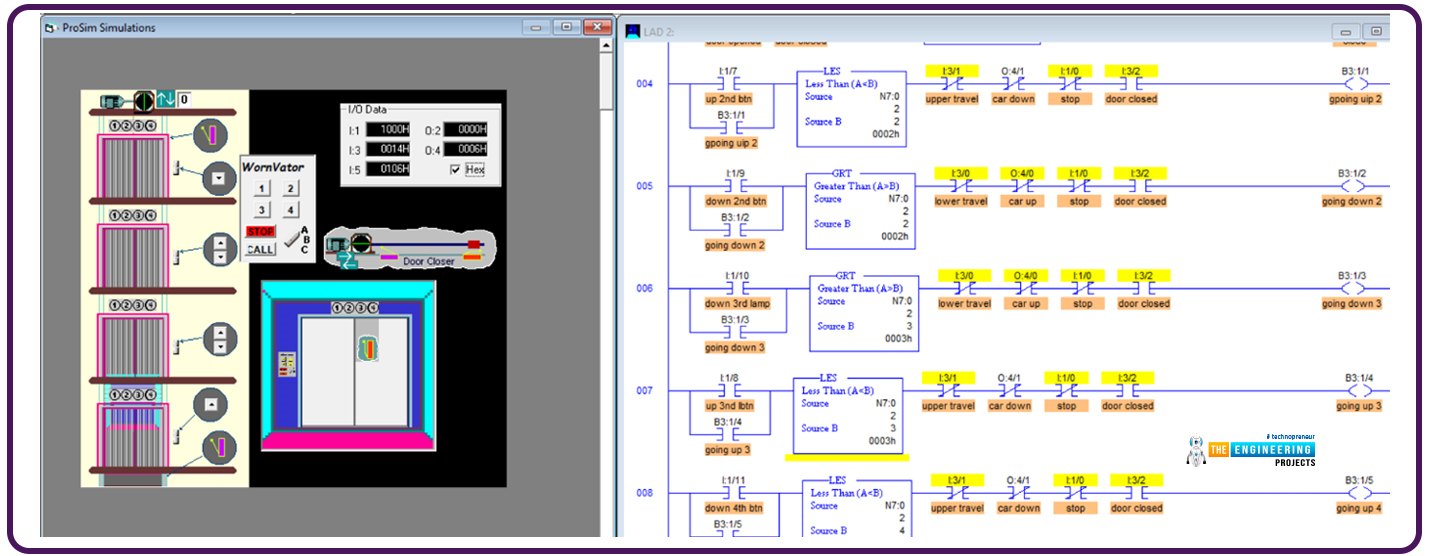
Hi, my friends and welcome back. I am happy to meet you again with a new tutorial of our PLC ladder logic programming series tutorials. Today we will complete what we started the last tutorial on the Elevator control project. We have a bunch of duties to complete together today. So let’s save time and jump into work immediately.

Project description:

Figure one shows the details that might help me describe the project between our hands. We have an elevator car that travels up and down and can stop on one of four floors based on the passengers’ requests. We have 6 push buttons on the wall next to the elevator door that can send requests to call the elevator. In addition, there is a control panel inside the elevator cabinet in which there are push buttons to request stations to reach floors 1, 2, 3, or 4. So now we are requested to manage all the scenarios and all requests received from inside and outside the elevator considering the priority of these requests to save energy and time management for the elevator traveling route. In the next section, the detailed requirements are listed.

The project requirements

The elevator should save all requests from the time they are requested until they are processed and cleared from the to-do list. 

The elevator should prioritize the requests in their direction of movement. For example, while he goes down, the requests for places located below his position will be given priority to do first. Similarly, when he goes up, the requests above the position where he is will be given priority. In that we, the waiting time will be reduced, and the energy and overall travelling distance will also be minimized. Because we have a lot to present in this significant project, let’s move on directly to the design and the ladder logic program that handles these requirements.

The design and logic of Elevator System

As usual, we are going to apply the divide-and-conquer rule. So the project will be divided into subtasks, and each task will be managed by one subroutine all subroutines are called in the main routine in sequence. Figure 2 shows the program structure which is composed of 5 subroutines. In the first routine, all initializations are called to be executed. So what’s in these subroutines? That is what we are going to show you below. So please follow up, my friends.

Figure 1 shows the ladder logic code of the first subroutine that initializes the work to start with the first floor as the initial position and going up as the initial moving direction and activate the action of performing the subsequent request or waiting for an incoming one.

The next subroutine is the heart of the logic, as it saves the requests and energizes the light indicators of the requested doors. Figure 3 shows a portion of the routine’s ladder logic code. As you notice, my friends, the first line is to tell the compiler that this is the start of the subroutine. The rung number 1 check if the request push button of the first floor inside the elevator’s car has been pressed and the elevator is not on the first floor; it will light the button lamp to show there is one request in the queue until the time comes to perform that request then the light will be turned off as we will demonstrate to you, guys. The next rungs, rungs number 2, 3, and 4, do the same for the corresponding keys inside the elevator’s car. If a push button is pressed, and its requested floor is not the current floor where the elevator is, then the corresponding lamp indicator is lighted, showing the request is saved in the queue, and when it is processed, the lamp indicator will be turned off. Now, moving on in the code, rung number 5 handles the outdoor request from pressing the first floor up push button. It simply checks the floor location. If it is not on the first floor, it lights; the lamp indicator of that push button shows that the request is in progress and will be turned off once it is processed. The following rungs do similarly the same function. But notice we have one push button for floors 1 and 4 while there are 2 push buttons for floors 2 and 3. So there are two rungs for handling the up and down direction requests.

One remaining thing for this subroutine is that the last rung confirms that when no requests are there so, the light on the first floor is turned on, showing that the elevator is on the first floor. Now my friends, let’s move to the next subroutine.

The next subroutine is called “track the vertical travel.” As you see, guys, the code checks in rung number 1 if the elevator is on the first floor, then it lit the first-floor light indicator and unlatched or de-energized the previous floor light, which is on the second floor and stops and opens the door. Now, when it reaches the second floor, indicated by the I:5 encoder, it lit the second floor and de-energized the lights of the next floors up and down, which are the first and third floors. Also, it checks if the second floor is being requested or in the queue list, then it stops the elevator and opens the door for getting or charging people who requested the second floor.

Figure 7 shows the ladder logic code of the second and last part of this routine; rung number 3, for example, checks if the elevator has reached the third floor; in this case, it lit the third-floor lamp indicator and turned off the next floors’ lamp indicators, i.e. floor 2 when it moves up from floor 2 to floor 3, or floor 4 when it goes down from floor 4 to floor 3. Also, if it goes down and the GO-Down request of the third floor is pressed, meaning there is a request in the queue, then it stops the elevator and opens the door for charging or discharging people who target the third floor. But, if it is going down and the Go-down, it stops the elevator and opens the door for charging or discharging the people.  And the last rung, number 4, handles the 4th-floor requests. If it is on the 4th floor, it just lights the light indicator on the 4th  floor and turns the light on the 3rd floor.

Now, my friends, the next routine is called “stop and open,” that handles opening the door at each destination. Figure 8 shows the logic; in rung number 1, if the door is not open for 2 seconds, then it is open the door, gives some time and then performs the subsequent request. When the door is opened, the request for the first floor is cleared. When it reaches floor number 2, and the door opens, if it goes up, clear the floor lightly and push the button to request the second floor, similarly, for the third and fourth floors.

Figure 9 shows the ladder logic code of the routine that decides which door will be bypassed and closing the door and go. It is called “ Do next or wait.” You can see, guys, it easily compares the moving direction and the requests in the queue based on the light status of the push buttons of all floors. Then bypass and resume with the door closed or wait and open the door for charging or discharging people.

Figure 10 shows the routine for closing the door at destinations. The routine is called “close door and move.” It simply checks if the door is closed and going up is requested, then lunch the move up the direction. But, if it is requested to move down, then latch the motor moving down. If no requests are moving up or down, enable the between-floors status. Now, my friends, we have explored all subroutines, and the time to test our logic and ladder logic program and subroutines has come. So let’s see if it is correct or needs some amendments.

Testing the ladder logic code

Figure 11 shows the initial state of the program while the elevator stops at the first floor, and the light indicators show the light of the first floor is lit, as you can see, my friends. Now let us command the push buttons requesting many requests to test.

From the initial position where the elevator is on the first floor, figure 12 shows the elevator has been requested as follows: on the second floor, it is requested to move up. On the third floor, it is requested to move down. On the fourth floor, it is requested to move down.

According to the requests and the sequences, it starts the journey from the first floor and stops at the second floor, as shown in figure 12.

Continuing his journey, he bypasses the third floor because it needs to go down. Show it gives priority to the request on the 4th floor, which is in his moving direction, as shown in figure 13.

Now, after reaching the most up, it changes direction and goes down to reach the third floor, which is the last request, as shown in figure 14. Notice, my friends, every time it reaches one requested place, it clears the light of the belonging request.

What’s next???

Clearly, the test successfully showed one scenario with all the test cases of moving, stopping, and bypassing. Thank you, friends, for following up on these points, and I hope you have enjoyed the project we have done together in this tutorial. Also, I promise the next tutorial will come with a new project from real life and learn more and enjoy practicing ladder logic programing together. So stay safe and be ready for our next tutorial.

Four floors Elevator using ladder logic programming

Hello, my friends and welcome back with one new tutorial of our ladder logic programming series. Today I am bringing one exciting project which you can see everywhere, in your home, work, and public places, which is an elevator. We will design a solution using plc ladder logic programming, which drives the elevator. Our elevator is composed of 4 floors and has all capabilities of large-scale elevators. So let’s get started and save time and jump into our tutorial.

Elevator Project

As you can see, Everyone figure 1 depicts the complete scene of the project and tells that the elevator we will manage has four floors to visit. On the first floor, there is only one outer request to call the car from any floor above, i.e. from floor 2, floor 3, or floor 4. While on the second floor, there are two request buttons to get the car from up or down floors and the same for floor 3. But floor 4, the last floor, has one request button to bring the elevator from the below floors, i.e. floors 1, 2, or 3. Also, the figure shows the request buttons inside the elevator car. There are request buttons for each floor, one-stop button, and one call button for emergencies. Now let’s move on to the inputs and outputs we will use in our logic:

Project inputs and outputs (IOs)

Smartly, we wrote one rung ladder logic as shown in figure 2, which does nothing but show the IOs the project has and names each IO with the descriptive name. We typically do such a rung for listing all IOs in one place to see the status of all IOs with one look. So what IOs do we have in this project? Well! You can see the request push button on the first floor from right to left and connected to input I:1/6. Also, the lamp indicator shows that the request is in progress. That indicator is connected to output O:2/6. In the second column, you can notice my friend’s two request push buttons connected to digital inputs I:1/9 and I:1/7. Also, for each request push button, there is an indicator lamp. The indicators of up and down requests for the second floor are connected to digital outputs O:2/9 and O:2/7.Similarly, in the next column, two push buttons request the elevator car to come from up or down; the request push buttons of the third floor are connected to digital inputs I:1/10 and I:1/8. Also, indicator lamps of the demands of the third floor are connected to digital outputs O:2/10 and O:2/8. And floor four has only one request push button and one indicator lamp associated with I:1/11 and O:2/11, respectively. It is essential to let you know that there are two safety limit switches to govern the travel limit in up and down directions. Digital input I:3/0, the one represents the lower limit travel while I:1/4 holds the upper limit travel signal. Also, there are inputs for the indoor control panel, as shown in the figure below. For example, indoor floor requests are connected to digital input I:1/1, I:1/2, I:1/3, and I:1/4 for requesting the first, second, third, and fourth floors. In addition, there is one push button to stop and another to call.

Design of elevator

Once more, let me remind you, my friends, that the best way to make it easy is to divide and conquer, meaning we break down the whole mission into sub-tasks and complete them to integrate at the end of the day for having the entire task achieved. Now, what are the requirements? Good, you ask such a question. Well! Our clients provided us with the image shown in figure 1 that gave us some details, but we still need to list the requirements and validate them with the customer before going further. That is crucial, my friends, because going further without confirmation of the conditions might yield some conflict later at a point in time. We will have made many efforts to cost many working hours that we want to retain. So again, what are the requirements? We need to recognize the position where the elevator is at any moment. Also, we need to command the elevator to go up or down based on where it is and the requested position. So now let’s divide the project into two main tasks. Determining the elevator position is our first one, and performing the requests will be the second task. So now, let’s move forward to the logic and coding of our ladder logic program.

Elevator ladder logic task 1

As we have mentioned earlier, in task 1, we want to determine the position of the elevator to decide where to direct the elevator up or down when one request comes. For example, you assume the elevator is on the 3rd floor, and a request comes from the second floor to call the elevator car. So, in this case, the logic of the program should command the elevator to go down. But if it was located on the 1st floor, in that case, it should direct in the up direction. Before going further in the position determination, we will show you how to manage the elevator door. Because we can not command the elevator to move while the door is open, figure 3 shows the door control lines of code in ladder logic programming. In rung number 2, we design the logic so that if the car is not moving up or down for a while, the door will be commanded to open by using the latch and unlatch command. In rung number 4, the door will be closed when the elevator does not move up or down, and the door is not opened or closed.

For testing the opening and closing management of the elevator door, Figures 4 and 5 show the door while opening and closing actions.

Ladder logic of elevator position

Figure 5.1 shows the ladder logic code for determining the elevator position; it utilizes the encoder’s feedback or reading and compares it using the limit instruction given the limit of each floor. For example, if the value reported by the encoder is between 293 to 295, which is the limit position of the first floor so, save one into the variable N7:0 that holds the current floor where the elevator dwells. And similarly, decide on the second, third, and fourth floors based on each floor's limit and the encoder's reading.

Now my friends, let’s move on to describing the code of the program step by step. Figure 6 depicts the ladder logic of the request handling logic. As you can see, my friends, in rung number 4, the requests from the second floor are being handled. When a request to move upward comes from the second floor, we test the elevator’s current position. If it is less than the requested position, which is floor 2, then it would go up. But if the position of the elevator is the upper floor, i.e. the 3rd or the 4th floor, then it should go down as instructed thanks to rung number 5. So let’s test this logic and see if it fulfills the requirements.

In the next step, after knowing the direction in which the elevator should move,  we code the commands to drive the motor to move up or down, as in figure 6.1, using rungs 10 and 11.

Testing the second-floor requests

Figure 7 shows the first scenario when the elevator was stopped on the first floor and was requested from the second floor. It shows the elevator goes up to its new requested target.

Figure 8 shows the second scenario when the elevator was stopped on the 3rd floor and was requested from the second floor. It shows the elevator goes down to its new requested target.

Figure 9 shows another test scenario when the elevator is requested to move from the second to the third floor.  Success is the result shown in figure 9 as it shows the elevator is moving up from the source place to the destination, the third floor,

Figure 10 depicts another test scenario of a request initiated from the third floor when the elevator is requested to move from the fourth to the third floor.  Success is the result shown in figure 10 as it shows the elevator is moving down from the source place, the fourth floor, to the destination, the third floor,

Figure 11 demonstrates another test scenario of a request initiated from the 4th  floor when the elevator is requested to move from the third floor.  The elevator moves up from the source place, the 3rd  floor, to the destination, the fourth floor,

Figure 12 shows another test scenario of a request initiated from the first floor when the elevator is requested to move from the third floor.  The elevator moves down from the source place, the 3rd  floor, to the destination, the 1st  floor.

What’s next???

First of all, I hope you have enjoyed the elevator project; please go through the tutorial and try to code the ladder logic and test it yourself for the best gain you can get from the tutorial. We have presented in this tutorial only some of it; we have done much great work, but we still have much work to do to complete the elevator project. So next time, the remaining project logic will be demonstrated, and you will enjoy learning and practicing ladder logic programming. So please stay safe and be ready for our following tutorial.

Large Format 3D Printing: A Revolution for Engineers

The world of large format 3D printing is dominated by a few key players who have emerged as the pioneers in this rapidly growing industry. Below are some of the biggest large format 3D printing companies and how they stand to benefit from this revolution:

  1. Stratasys: Stratasys is a leading provider of large format 3D printing solutions, offering a range of industrial-grade printers that are capable of producing high-quality prototypes and end-use parts. With its powerful proprietary Fused Deposition Modeling (FDM) technology, Stratasys is well positioned to capitalize on the growing demand for large format 3D Printing solutions.

  2. HP: HP is one of the largest and most well-known technology companies in the world, and it has recently entered the large format 3D printing market with its HP Jet Fusion technology. With its proven track record in the technology industry, HP has the resources and expertise to quickly establish itself as a leader in the large format 3D printing market.

  3. Massivit3D: Massivit3D is a leading provider of large format 3D printing solutions for the Engineering, Visual Communications, Entertainment, Academia, Interior Design, and Architectural markets. Leveraging its proprietary Gel Dispensing Printing (GDP) technology, the company’s solutions enable rapid and cost-effective production of scale 1 models and parts.

  4. Carbon: Carbon is a leading provider of large format 3D printing solutions that use Digital Light Synthesis (DLS) technology to produce high-quality, end-use parts. With its cutting-edge technology and strong focus on customer satisfaction, Carbon is well positioned to continue to grow and expand its presence in the large format 3D printing market.

These companies stand to benefit greatly from the continued growth of the large format 3D printing market as more and more engineers, manufacturers, and other businesses adopt this innovative technology. By providing high-quality, cost-effective solutions for large format 3D Printing, these companies are helping to drive the growth of the industry and revolutionize the way products are designed and manufactured.

Engineers Stand To Benefit Massively


Large format 3D printing has revolutionized the engineering world by allowing engineers to quickly and easily create prototypes, designs, and finished products. By streamlining the manufacturing process, engineers can now focus on developing the best designs and products possible, instead of being bogged down by the time-consuming task of building prototypes by hand.

One of the biggest advantages of large format 3D printing is the ability to produce parts and prototypes at a much faster rate than traditional manufacturing methods. This means that engineers can test and refine their designs in a fraction of the time it would take using traditional methods. In addition, large format 3D printing can be performed on a much larger scale, making it easier to produce large or complex parts and prototypes that would be difficult or impossible to produce using traditional methods.

Another advantage of large format 3D printing is its ability to produce high-quality, precise parts and prototypes. This is because 3D printing uses computer-aided design (CAD) software to create detailed, accurate models. This precision and accuracy is essential for engineers, who need to ensure that their designs are functional and fit for purpose.

In addition, large format 3D printing is incredibly versatile and flexible. Engineers can print parts in a variety of materials, including plastic, metal, and composites, to produce prototypes that are representative of the final product. This means that they can test their designs in real-world conditions, which is essential for ensuring that their designs are robust and reliable.

Finally, large format 3D printing is also cost-effective. Traditional manufacturing methods can be expensive, especially when it comes to producing large or complex parts. With 3D printing, engineers can produce prototypes and parts at a much lower cost, which means they can focus their resources on developing the best possible designs and products.

But, the above are just advantages to the world of engineering on a macro-level. How does large format 3D printing help engineers specifically? Here are just several concise examples:

  • Design Verification: Large format 3D printing allows engineers to produce prototypes of their designs in a matter of hours. This enables engineers to quickly verify the design’s form, fit, and function, leading to faster product development cycles.

  • Reduced Costs: By producing prototypes in-house, engineers can significantly reduce the costs associated with traditional prototype development processes such as tooling, shipping, and storage.

  • Improved Accuracy: Large format 3D printing provides engineers with highly accurate and precise parts. This level of precision can lead to better-performing and longer-lasting products, as well as reduced production time and costs.

  • Material Options: Large format 3D printing technology offers a wide range of material options, including plastics, metals, ceramics, and composites. This diversity of materials enables engineers to choose the best material for their specific applications, leading to improved performance and durability.

  • Customization: Large format 3D printing allows engineers to produce highly customized and complex parts, which are not possible to produce through traditional manufacturing processes. This level of customization can lead to improved product performance and increased customer satisfaction.

  • Increased Productivity: Large format 3D printing can significantly increase the productivity of engineers, as it enables them to quickly produce and test prototypes, reducing the overall time required to bring a product to market.

  • Sustainability: Large format 3D printing is a more sustainable manufacturing method compared to traditional methods as it reduces waste and energy consumption. Additionally, it enables engineers to produce only the parts they need, reducing the overall carbon footprint associated with the production process.

In conclusion, large format 3D printing is a powerful tool that can help engineers streamline their work. By allowing them to quickly and easily produce high-quality, precise parts and prototypes, engineers can focus on developing the best designs and products possible. Whether it's reducing time-to-market, improving product quality, or reducing costs, large format 3D printing is a valuable tool that should be considered by all engineers looking to improve their workflow.

Advance Counter Functions in PLC Ladder Logic

Hi, my friends. Welcome to share a new tutorial in our ladder logic programming series. Today we will discuss counters in ladder logic programming using an expert’s view. So let’s wear the glasses of an expert in ladder logic programming and look deeply into counters, the types of counters, their variables and bits. In addition, techniques of using counters to solve a different kinds of problems that need counting. And without questions like every time, we will enjoy practicing programming and simulating all about counters. So with no further delay, let’s jump into our tutorial and nail that counters.

Counters in real life

Tell me, guys, if you can imagine an industrial project or machine that does not need to count parts, products, or processing cycles. Actually, in most cases in industry and practical operations, you will find counters everywhere you visit production lines or operating machines. So now, what are the types of counters and what is inside or belongs to counters, their variables and bits? Also, what are the techniques for utilizing counters in ladder logic programming?

Counter Types

As regards functionality, counters can be divided into count up and count down, as shown in figure 1. Counter-up and down instruction blocks are shown in CTU and CTD. One is to count up, and the other is used to count down. They are different in functionality. However, they have the same variables, parameters, and data bits. So let’s discuss all this data belonging to counters.

Counter data bits

Figure 2 images the data of counters. On the left tree, you guys notice the counters in the data files and on the right, see many counters that you can use in your ladder logic program. Also, the main variables are the preset value and the accumulator value by which you tell the program the counter will count up or down to what value. Also, you should know the left side of the rung is the input to the counter to activate it and let it counts when the input is high. While the right side is the output data bit of the counter which is the enable EN bit that tells the counter block has run okay. And the done bit DN that informs the counter reached the desired preset value by turning into high when the accumulator variable ACCUM goes equal to the PRESET value.

How to use counters in PLC?

Figure 3 shows the best practice for utilizing counters and handling their logic. In the first rung, we used input I:1/0 to control the CTU counter set to count up to 10. So every time the input to the counter turns from low to high, the counter will count up by incrementing the ACCUM. Also, we have used the RES instruction to reset the counter at any time by having the input I:1/1. So by having the input I:1/1 turned to high, the counter’s accum will reset to zero. Now moving to the important part that provides the clue to process and handle counters. Starting from rung 3, the comparison instructions are used to check the ACCUM and control the outputs according to the logic we designed for. For example, in rung number 3, the EQU instruction compares the accumulator C5:1.ACC to zero to check if they are equal and if so, it energizes output O:20/0. In contrast, the NEQ compares instructions to check the inequality of the source C5:1.ACC and zero to decide the next state of output O:2/0. Furthermore, Runge 004 combines greater than GTR and less than instructions to check if the accumulator value is between two values and decide the state of the output on the right. Continuing further, the greater than or equal GTE and less than or equal LTE are used to check the accumulator as well but considering the boundary values.

Counter example with simulation

Figure 4 demonstrates an example of the counter in which input I:1/1 has been used to control the counter input, and input I:1/2 is used to reset the counter. Also, in the third runge, the done bit of the counter controls the state of output O:4/0.

Simulating counter example

Figure 5 shows the simulation of the counter’s example. It shows the counter counts up every transition from low to high of the input I:1/1. Also, it shows that the output’s state of O:4/0 has come to high when the counter’s accumulator has reached the value of the preset value.

Also, as you see, friends, when input I:1/2 has clicked, the counter accumulator has been reset to zero thanks to utilizing the reset instruction RES.

Example of using comparison instruction with counters

Figure 7 demonstrates how using the comparison instructions to handle counters by comparing the accumulator of the counters, checking its value and controlling outputs accordingly. For example, in rung 002, output O:4/0 will go high when the counter’s done bit goes high or when it counts to 10. Also, output O: 4/4 will be turned to high in rung 004 when the accumulator of the counter is something between 3 and 7 but not 3 and 7 themselves. To include boundaries 3 and 7, the comparison instruction less than or equal LTE and greater than or equal GTE are used as rung 005 to control O:4/7. Also in rung 005. The compare instruction EQ is used to decide the state of output Q:4/6. In the simulated running example, when the counter’s accumulator was equal to 3, outputs O:4/7 and O:4/6 turned to true based on the results of the comparison instructions.

Tracking the data table

Exploring the data files on the left part of the view, you can also see the values and states of the counter’s variables and data bits. The value PRE is 10; the accumulator variable ACC is 10. So, the done bit DN is true or 1. Also, the function of the counter with cunting up is shown as 1.

Small PLC project using counters

After showing how to use the comparison instructions and introducing the counter variables and data bits, it is time to do something with counters. And here it is in figure 9; you can see a funny example of singers. In that example, we use two counters, CTU and CTD, to count up and down. The program utilizes flag B3:0/1 to manage which counter will be activated. As you see in rung number 1, when b3:0/1 is false, the counter CTU will be active to count up. By the time the counter reaches 10, its done bit turns high to activate flag B3:0/1. Then, the counter CTD is active to count back down to zero. And finally, when the CTD counts down until reaching zero, the flag B3:0/1 has turned off using unlatch (U) instruction to repeat the process again and again. So let’s see some tests for the implemented code to check if it is correct or if something needs to be amended.

Figure 10 shows the counter CTU is counting up every chance the input I:0/1 turns from OFF to ON.

Figure 11 shows how the logic turns to activate CTD after counter CTU reaches its preset value by flipping flag B3:0/1.

Figure 12 shows that the process has returned to count up after the accumulator has reached zero.

Now, guys, we have nailed counters showing the variables and related data bits and techniques of utilizing the comparison instructions to handle the counters logically. Thanks, guys, for following me up here . I hope you have enjoyed learning and practicing the counters in ladder logic programming. I hope to meet again with an interesting tutorial of our series of ladder logic programming.

Advance Timer Functions in PLC Ladder Logic Programming

Believing in the essence of timers in ladder logic programming, we come today with a new tutorial in which we are going to show you all about timers, the types of timers, what’s inside timers’ block of parameters, variables, and bits. In addition, techniques for using timers will be explored, and for sure, we are going to practice what we learn using the simulator. So let’s get started with our tutorial.

Timers in ladder logic programming

Guys, this is not the first time we’ve talked about timers. However, this time we are going to look into timers deeply and use the glasses of practical approach. So figure 1 shows the most important types of timers in ladder logic from left to right: the on-delay, off-delay, and retentive timers. There are differences in functionality. However, they all have the same parameters, variables, and bits. For example, the on-delay timer (TON) works by starting counting by getting the high logic state of its input. And bit goes ON when and only when the counter reaches the preset value. While the off-delay timer (OFF-DELAY) employs starting with the high logic of its Done bit once it has a high logic of its input. And when its high input stat is gone and turns to low. It starts counting until reaching the preset value, and then the done bit goes off. On the other hand, the retentive timer keeps accumulating the time while the input is energized until it reaches the preset value, at then the Done bit goes on. You can see, my friends, how are different in functionality to help you get a way for every problem related to timers. Despite that variety in behavior, they have the same data, as you can see in each timer block. So now, what are these data, and how can we utilize them in ladder logic programming? that is what we are going to learn together in this tutorial.

Timer data in PLC

Well! Timer data can be demonstrated in figure 2. You can see guys in the tree view windows below; the data section shows the timers data in which there are dozens of timers you can use through long your program. But what does the data include? Well! The data has timer bits and variables, as shown on the right side of the window. The most important variables are the preset variable (PRE), in which we set the value of the time at which we require the timer to act ON. The other variable is the accumulator variable ACC that we use to know what the counted time is so far. The logic says the timer keeps increments accumulator until reaching the preset value. Okay, then what happens when the accumulator reaches the preset value? Exactly, the timer needs to indicate that he reaches the target.  There are so-called timer bits like the timing bit TT that reports the timer is timing, and the DONE bit that tells the accumulator has reached the preset value. And also the EN bit that shows the completion of execution of the timing instruction.

Most Common PLC Timer Types

Well, timers can be categorized based on their functionality and the way they work. For instance, the ON-DELAY timer starts timing when it gets a trigger signal which is the high state of its input. By reaching the preset value, the output will have been energized as long as the input is high. Please, guys, see the timing diagram in Figure 3 which depicts the timing diagram of the input and output of the ON-DELAY timer. It shows the timer contact goes on after counting the preset time value since it receives a high logic on its input coil.

The second but same important kind of timer is the OFF-DELAY timer. This timer starts energizing its contact or output from the moment it receives high logic input. Then after that input goes low, the output remains high in the logic state for as long as the preset value has been specified. Please, my friends, find the operation cleared in figure 4 below, which demonstrates the operation by the language of the time. In this example, the timer coil has been energized, and its contact goes high. And when the coil de-energized, the contact remained high for 5 seconds which is the preset amount of time of the timer.

The third timer we are going to show today is the retentive timer. So what does that timer do? Well, that timer accumulates the time whenever its coil is ON. The timing diagram is shown below in figure 5.  More details about the timing diagram of retentive timers, what figure 5 demonstrates. You can notice, my friends, as long as the input is high, the timer accumulator keeps accumulating the time until one reset signal appears, then it resets the time. But it returns back, accumulating the time whenever the input is true.

Now we will show some examples to let you understand how to employ the timer variables and bits as well. Figure 6 shows the timer block of an OFF-DELAY timer. You can see, guys, the timer’s name is T4:1, the time base is set to 00.1, and the preset value is set to 100, meaning it is designed to time for 10 seconds that can be determined by multiplying the time base to the preset value. Also, you can see that the first rung used input I:1/0 to enable the timer by energizing its coil. Rungs 1 to 3 show how you guys might use the timer bits. For example, in rung number 1, the enable bit of the timer is used to energize output O:2/0. Similarly, the timing bit TT of the timer is utilized to turn on output O:2/1 in rung 002. While the done bit DN energizes output O:2/2 as in rung 003.

Simulating one example

Here it is the simulation of one example to show how the timers bits and variables can set and used. In figure 7, the timer of type on-delay T4:4 is used and set to time for 10 seconds by setting the preset to 100 and the time base to one-tenth 0.1. the timer’s bits are used as you can see my friends to activate different outputs.

Example showing timers types

Another example demonstrated in figure 8 to show the on-delay and off-delay timers working together to fulfill the requested logic.

Retentive Timer example in Ladder Logic

Figure 10 shows an example to demonstrate the utilization of a retentive timer type. You can see the timer block of the retentive timer RTO and how it is accumulating the time whenever the input is high without resetting when the input is turned off.

Timers programming techniques

Going to one of the most important parts of our tutorial is how professionally you guys can use the timers to solve whatever problem you have. The techniques to use timers that come with experience. For example, figure 11 shows the cascading timing technique in which you can use multiple timers based on each other in a cascading way. You see, guys, how timer T4:2 depends on the Done bit of timer T4:1 in cascading approach. Why do we need to use two timers in such a way when we can use only one with a preset value equal to the sum of the two timers? That’s smart to be asked. But the answer also is intelligent, which tells us we might need to do some action in between. For example, when timer number one has done timing, we might energize one output, and after the second, we perform another action depending on the first timer.

Reset the timers in Ladder Logic

Figure 12 shows the technique to reset the timer by having one normal close contact in the way of its input to control energizing the timer coil. In that very example demonstrated by figure 12, the timer Done bit itself is used to reset the timer, meaning that when the time contact acted ON, it is the time to reset the timer and like that, we can guarantee the timer keeps repeating the process forever.

And at that point, I would like to thank all my friends for following me till the end of that tutorial, and I hope you have learnt some knowledge and enjoyed practicing one of the most important topics in ladder logic programming, Timers. For recapping have nailed the timers by demonstrating the variables and bits of the timers and the types and techniques of using the timers to flexibly and professionally can deal with different situations and solve any problems related to using the time.

CNC milling: things you need to know

Milling is a machining process that can create detailed or complex shapes from metal, plastic, or other materials. The CNC milling process involves using a computer to control the motion of a rotary cutter that removes material from a workpiece. This article will discuss things you need to know about the CNC milling process.


What is CNC milling, and what are its uses?

CNC milling is a machining process that uses computer numerical control (CNC) to cut materials precisely. It can produce complex shapes with high accuracy and repeatability from metal, plastic, or other materials. It is used for many applications, including prototyping, manufacturing parts, making moulds and dies, creating fixtures for production lines, producing 3D sculptures and more.

What are the advantages of CNC milling? 

The most significant benefit of CNC milling is its ability to produce exact parts with tight tolerances. Other advantages include speed and consistency in production and flexibility in design since it can be automated easily compared to manual operations. Additionally, because it supports multiple types of machines with different tooling, it is a versatile solution for many manufacturing needs.

What are the different types of CNC mills available on the market?

There are many different types of CNC mills available today, including vertical and horizontal mills. Vertical mills are designed for operations that require cutting or drilling straight down into material and have a spindle axis perpendicular to the table. Horizontal mills are designed for operations in which the workpiece is fed parallel to its length along an x-y axis.

What materials can be milled by CNC machines? 

CNC machines can mill nearly any material, from aluminium alloys to plastics, composites, and even hardwoods. It is essential to consider the specific properties of your material when selecting the best tooling for your application. Generally speaking, more complex materials such as steel require more specialized tools, while softer materials can be machined using standard-issue tooling.


What are the different CNC milling techniques? 

CNC milling is often carried out in multiple passes, depending on the complexity of the design and material being milled. The most common techniques used in CNC milling include rough cutting, finishing, slotting, drilling, and engraving. Each technique has its tools that must be chosen based on the workpiece material and desired finish.

How does one find a reliable CNC milling service? 

When looking for a CNC milling service provider, one must consider their experience with CNC machines and the type of parts they specialize in creating. Additionally, it is vital to look for certified CNC milling service providers with an established quality management system. Doing your due diligence on a CNC milling service provider will help you find the best fit for your application.

What safety considerations should be taken when using CNC machines? 

Safety should always be the top priority when operating a CNC machine. Proper training and use of personal protective equipment, along with regular CNC machine maintenance, are necessary to ensure safe operation. It is also essential to be aware of any hazardous materials or processes used during CNC machining so that proper precautions can be taken.

What are CNC software programs available?

CNC machinists typically use CNC software programs to design and create their components. Popular CNC software programs include CAMWorks, Mastercam, Fusion 360, and Autodesk Inventor. Each CNC program has its own tools and capabilities that allow CNC machinists to create the exact parts they need for a given application.

How to choose the suitable CNC mill for your needs

When selecting the suitable CNC mill for your needs, it is essential to consider how precise and repeatable the parts will need to be. You must also consider what type of material will be machined and any special features that would benefit your application. It is vital to work with a CNC milling service provider with experience in the type of part you are trying to manufacture so that they can advise on the best CNC machine for your needs.

Tips for getting started with CNC milling

When getting started with CNC milling, it is essential to clearly understand the project goals and machining requirements. You should also be familiar with CNC machine operations, such as setting up tools and measuring material properties. It is also essential to have a plan for managing data so that any changes made during CNC machining can be tracked. Finally, it is beneficial to practice CNC milling on scrap materials before attempting to machine a final product.

Conclusion

CNC milling is a versatile machining method that can be used to create a variety of components from soft and hard materials. It is vital to research CNC machines, CNC software programs, and CNC milling service providers to find the best fit for your application. Additionally, safety considerations, as well as tips for getting started, should also be taken into consideration when beginning CNC machining projects. With the proper knowledge and equipment, CNC milling can open up many possibilities regarding part design and production capabilities.

Syed Zain Nasir

I am Syed Zain Nasir, the founder of <a href=https://www.TheEngineeringProjects.com/>The Engineering Projects</a> (TEP). I am a programmer since 2009 before that I just search things, make small projects and now I am sharing my knowledge through this platform.I also work as a freelancer and did many projects related to programming and electrical circuitry. <a href=https://plus.google.com/+SyedZainNasir/>My Google Profile+</a>

Share
Published by
Syed Zain Nasir