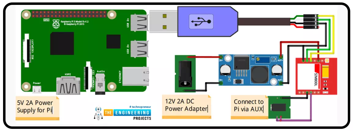
A low-literate audience can nevertheless have their voices heard and their questions answered by using an IVR system, as has been proven time and time again. However, achieving such aims in a development setting calls for a cheap system that welcomes input from various parties. RASP-IVR is an inexpensive IVR system that operates on a PI 4 and a local Global System for Mobile Communications modem. RASP-IVR was designed as an open-source, community-driven solution. It's unusual to find a customer-focused company that still uses human operators rather than an interactive voice response system. Credit card companies typically have IVR systems that can be used to make payments or file fraud reports. Airlines use elaborate IVR systems to schedule flights and check their current status. To facili ...
Introduction
Welcome to the following tutorial in our raspberry pi four programming tutorial. In the previous tutorial, we learned how to build a raspberry pi four website monitoring tool. We say how beautiful soap is applied in browser automation tasks such as tracking website activities. But in this guide will discover how to utilize our Raspberry Pi 4 as a wifi repeater. If you want a lag-free wireless network, a wifi Wireless Adapter is exactly what you need. You may want to set up a wifi repeater if your signal is weak in certain rooms of your home or if you have entirely lost service in one or more rooms that are too small to accommodate your current network setup. If you want to increase the range of the wifi connection without breaking the bank or wasting a lot of energy, consider ...
Introduction
Welcome to the next tutorial in our raspberry pi programming. In the previous tutorial, we learned how we could run Xbox cloud on our pi 4. We found that we can run any game easily without lag or having raspberry pi shut down, proving that pi 4 is quite a powerful minicomputer. However, this tutorial will demonstrate how to use Python on raspberry to monitor websites. This Python program will execute on Pi 4 and watch over a website, alerting you whenever it changes or goes down. This is accomplished by keeping a straightforward webpage duplicate locally and monitoring for updates. This webpage monitor is straightforward, so it should work well on pi Zero. Throughout this tutorial, we will demonstrate how to develop your custom code to monitor a webpage. With this information ...
Introduction
Greetings, and welcome to the next section of our Raspberry Pi 4 tutorials. In the last section, we discovered how to set up and run our self-host bitwarden on our Raspberry Pi. We learned how to set up admin panels and perform a wide range of actions, such as limiting the creation of new accounts and users for security purposes. However, in this guide, we will discover how to configure a PS3 or PS4 joystick with our raspberry pi and set up and run Xbox cloud gaming on our Pi 4.
Components
Raspberry pi 4
SD card
Power supply
Ethernet cable or wifi
Xbox controller
Xbox game pass ultimate subscription
USB keyboard
USB mouse
HDMI cable
Through a service called Xbox Cloud Gaming, users may play a wide variety of games witho ...
Following this, we will configure bitwarden and host it on our Raspberry Pi 4. The last tutorial discussed utilizing a Raspberry Pi to install and run zeroTire on pi 4. By the end of the project, you will have learned how to set up a Raspberry Pi 4 with the necessary software for password management, including bitwarden, docker containers, and portainer, and how to configure their respective user interfaces.
Why Would You Do This?
An effective password manager is a must-have. For the past decade-plus, I've relied on a password manager. The catch is that not all security-focused apps are created equal. Initially, I relied on password managers in my browser, but I soon switched to KeePass. It was an intelligent move ten years ago. The export f ...
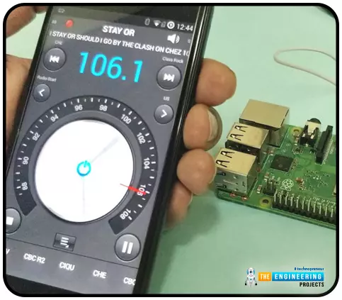
Throughout our lives, we've relied on Radio and tv stations to keep us engaged. While we're on the subject of contradictions, it's also fair to say that these Stations can become tedious at times due to the RJ rambling on about nothing or annoying advertisements, and this may have left you wondering why you can't own a Radio station to broadcast your data over short distances.
Almost any electronics technician uses coils and other hardware to make an FM transmitter, although the tuning process is time-consuming and difficult. Setting up your FM station and going live in your neighborhood shouldn't take more than 30 minutes using an RPi. If you use the right antenna, you must be able to transmit to your school or community within 50 meters. Wow, th ...
Thank you for joining us for yet another session of this series on Raspberry Pi programming. In the previous tutorial, we built a motion sensor-based security system with an alarm. Additionally, we discovered how to use Twilio to notify the administrator whenever an alarm is triggered. However, in this tutorial, we'll learn how to build a stop motion film system using raspberry pi 4.
What you will make
With a Raspberry Pi, Py, and a pi-camera module to capture images, you can create a stop-motion animated video. In addition, we'll learn about the various kinds of stop motion systems and their advantages and disadvantages.
The possibilities are endless when it comes to using LEGO to create animations!
...
Our next step in the Raspberry Pi training program is to get zero tiers up and run on a Raspberry Pi 4. How to utilize a Raspberry Pi to measure internet speed and store the results in Grafana or Onedrive was the topic of the last piece. During the project, you will discover how to install ZeroTier on a Raspberry Pi and get it up and running. We will also learn how to set up a firewall to secure our network.
Components
Raspberry pi 4
Power supply
Ethernet or wifi
What is zeroTier
ZeroTier is a software that provides a streamlined web-based interface for constructing virtual networks connecting various gadgets. Somewhat akin to configuring a virtual private network on a Raspberry Pi, these networks exist only in cyberspace. The process o ...
Following up on our Raspberry Pi programming course is the next lesson. In the previous post, we learned how to construct an FM radio using a Raspberry Pi. Analog FM broadcasting's circuit construction was also studied in detail. How to use a Raspberry Pi as an internet speed meter and save the data in Grafana or Google Drive is the subject of this article.
You can use this article if you want to keep track of how your downloads, uploads, and ping speeds change over time, and it's easy to use. In addition, you can use this to determine when your internet is at its busiest or if your internet speed has deteriorated. We'll demonstrate how to use Ookla's Internet speed test command-line interface in conjunction with Python code to create an internet speed meter.
...
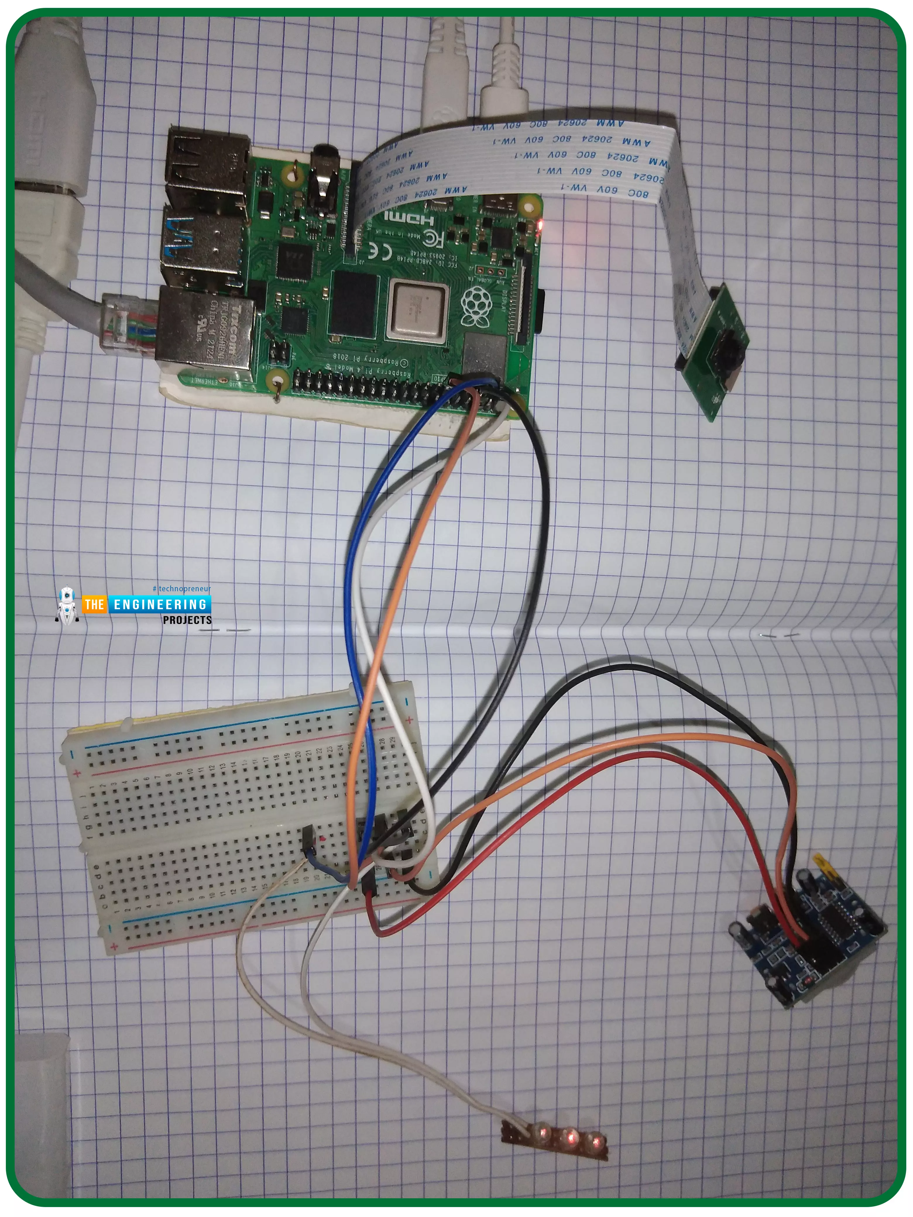
Thank you for joining us for yet another session of this series on Raspberry Pi programming. In the preceding tutorial, we constructed a personal Twitter bot using Tweepy, a Py framework for querying the Twitter application programming interface. We also constructed a Response to robot mentions that would post a response to everybody's tweet mentioning it with a certain keyword. However, in this tutorial, we will implement a security system using a motion sensor with an alarm. This is what it looks like:
PIR Motion Sensors can be implemented with RPi by understanding how it is connected to a Raspberry Pi. Whenever the motion sensor detects human movement, an alarm is triggered in this project and the LEDs blink. You may create a simple motion-det ...