 BETA
52 kHz buck regulator
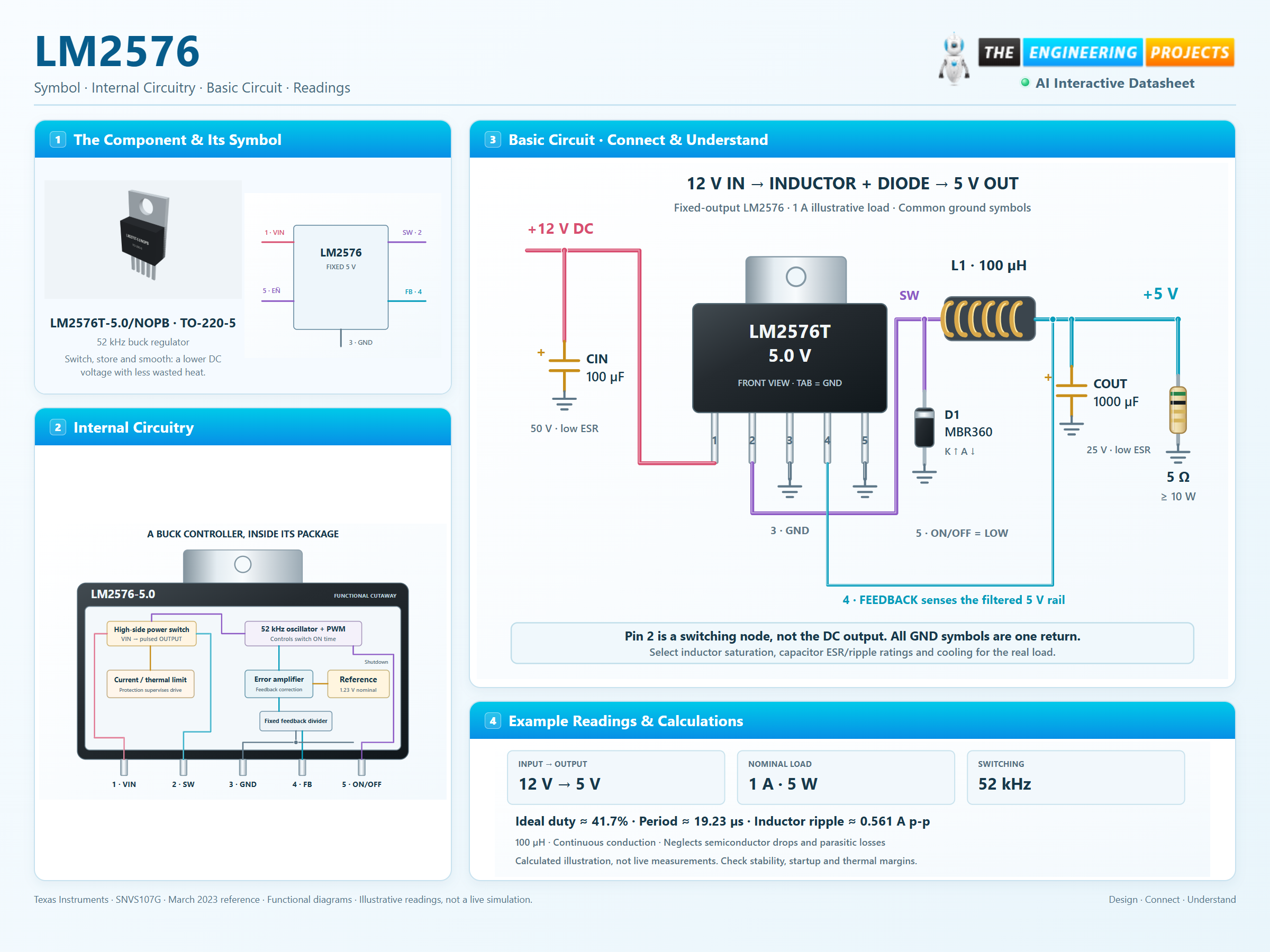
LM2576 Working Principle
Learn how LM2576 works with an illustrated explanation and practical readings.
Package view
LM2576 at a glance
Follow the labeled connections and functional stages
How it works
3 stages · Explore one step at a time
Switch ON: charge the inductor
The internal transistor connects VIN to pin 2. Inductor current rises while energy flows toward the load.
Switch OFF: keep current flowing
The catch diode conducts from ground into the switch node. Inductor current continues toward the load and falls gradually.
Close the control loop
Feedback senses the filtered output. The controller adjusts pulse width, while current limiting and thermal shutdown handle abnormal conditions.
Step 1 of 3