Real View
Build a negative rail—and keep the polarity clear.
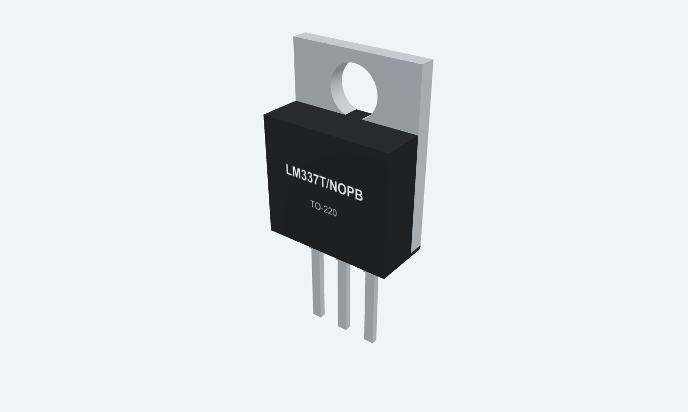
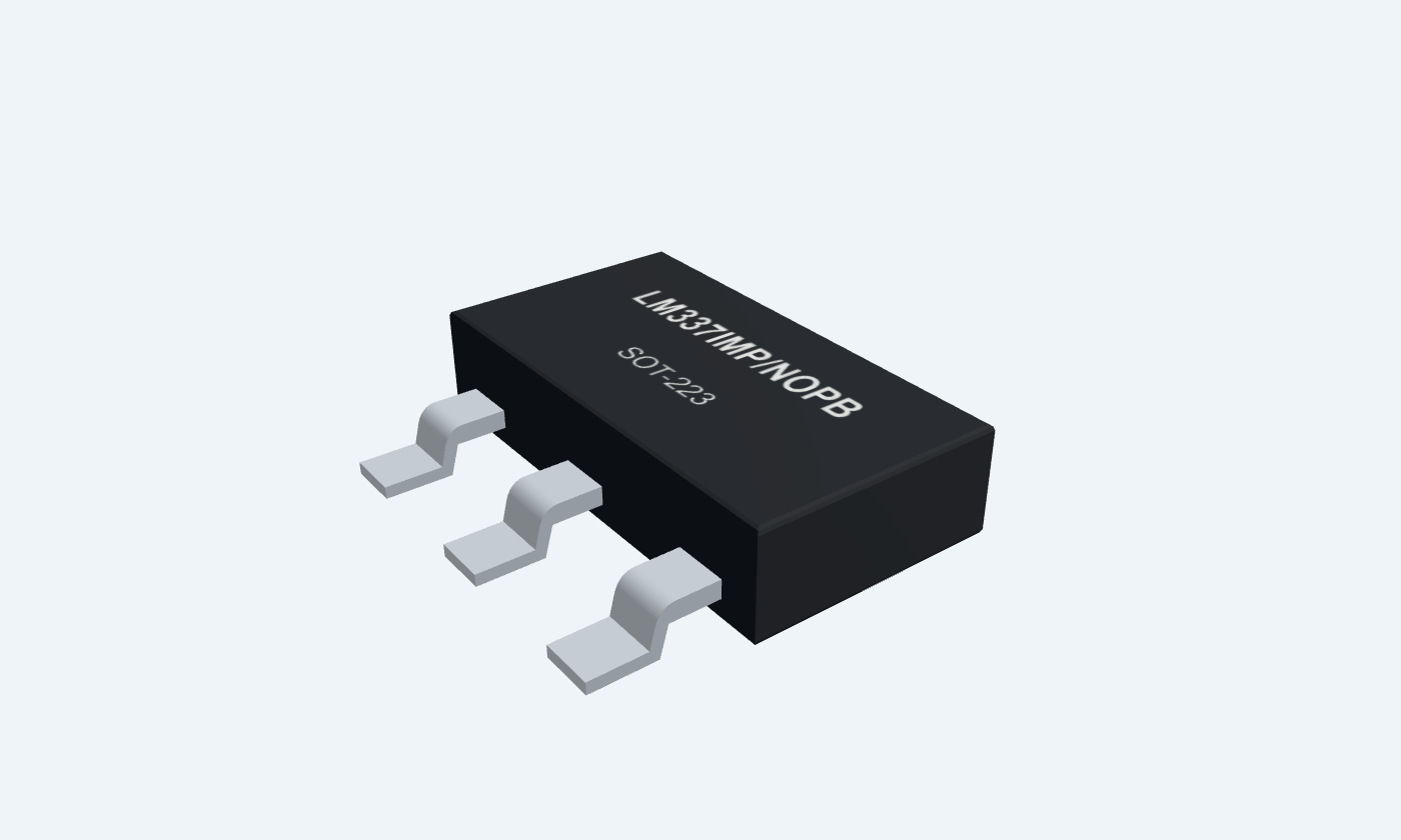
LM337 is an adjustable negative linear regulator in the 1.5 A class. It maintains approximately −1.25 V from OUTPUT to ADJ; two resistors establish the output relative to the common return. Its nominal adjustment span is −1.25 to −37 V with sufficient headroom, load and cooling. The front-view TO-220 pins are ADJ, IN and OUT. The metal tab is connected to the negative input. In SOT-223, the broad input tab is also numbered 4, so all four physical contacts are mapped here. This reference follows TI LM337-N, with LM337T/NOPB and LM337IMP/NOPB package views. A −9 V-to−5 V example shows the divider, required output capacitor and reversed capacitor polarity. The SMD order has an extended temperature range, but the common electrical table below retains the datasheet’s stated 0–125°C LM337-N conditions.
Select a pin to explore its connection
Click a lead or use the arrow keys. Front view · marking toward you · ADJ1, IN2, OUT3
The regulator holds OUTPUT approximately 1.25 V below ADJ.
Connect R1 from OUT to ADJ and R2 from ADJ to the common return.
ADJ is not ground. Adjustment current flows into this terminal.
Accepts a negative supply more negative than the required output. The TO-220 tab and SOT-223 tab 4 are also IN.
Connect −9 V in the example; keep the live input tab isolated from grounded metal.
This pin assignment differs from positive LM317/LM350 regulators.
Supplies the load at a controlled negative voltage relative to the common return.
Connect R1, the load and the required output capacitor here.
Polarized output capacitors have their positive end at the common return, not at OUT.
The broad SOT-223 contact is internally connected to input lead 2.
Connect to the negative input copper and provide an adequate thermal path.
This is a separate physical contact on the same IN node; it is not ground.
OUT sits about 1.25 V below ADJ. The divider lifts ADJ below the common return, setting a negative output. Keep the package pinout and capacitor polarity explicit.
LM337T/NOPB · TO-220
| Property | Details |
|---|---|
| Manufacturer | Texas Instruments |
| Part number | LM337T/NOPB |
| Package | TO-220 |
| Connections | 3 pins |
| Mounting | Through-hole |
| Lead pitch | 2.54 mm |
| Package code | NDE |
| Thermal reference | 0–125°C operating junction; tab = IN |
TI LM337-N electrical column
Scroll sideways to see all columns.
| Parameter | Value | Conditions / notes |
|---|---|---|
| Nominal output adjustment | −1.25 to −37 V | With adequate differential voltage, loading and cooling |
| TO-220 order range | 0–125°C junction | LM337T/NOPB |
| SOT-223 order range | −40–125°C junction | LM337IMP/NOPB; do not extend the 0–125°C electrical table implicitly |
| Reference at 25°C | −1.213 / −1.25 / −1.287 V | Manufacturer MIN / TYP / MAX signed entries |
| Reference over stated LM337-N range | −1.20 / −1.25 / −1.30 V | 0–125°C; stated differential and load conditions |
| Adjustment-pin current | 65 µA typical; 100 µA maximum | Flows into ADJ |
| Adjustment current change | 2 µA typical; 5 µA maximum | 10 mA–IMAX; 3–40 V differential; 25°C |
No specifications match. Try a parameter name or a unit.
Electrical test baseline: 5 V input-output differential and 0.5 A load for TO-220/SOT-223, unless specified. Observe the source power conditions.
Constant-junction pulse measurements
Scroll sideways to see all columns.
| Parameter | Value | Conditions / notes |
|---|---|---|
| Line regulation at 25°C | 0.01%/V typical; 0.04%/V maximum | 3–40 V differential; 10 mA load |
| Line regulation over stated range | 0.02%/V typical; 0.07%/V maximum | 3–40 V differential |
| Load regulation at 25°C | 0.3% typical; 1% maximum | 10 mA–IMAX |
| Load regulation over stated range | 0.3% typical; 1.5% maximum | Constant-junction test conditions |
| Thermal regulation | 0.003%/W typical; 0.04%/W maximum | 10 ms pulse; 25°C |
| Ripple rejection without CADJ | 60 dB typical | −10 V output; 120 Hz |
| Ripple rejection with 10 µF CADJ | 66 dB minimum; 77 dB typical | −10 V output; 120 Hz |
| Output noise | 0.003% of output typical | RMS; 10 Hz–10 kHz; 25°C |
No specifications match. Try a parameter name or a unit.
Typical values are not guaranteed extremes.
Current capability depends on voltage drop
Scroll sideways to see all columns.
| Parameter | Value | Conditions / notes |
|---|---|---|
| Minimum load at ≤40 V differential | 2.5 mA typical; 10 mA maximum | Guarantee minimum current to maintain regulation |
| Minimum load at ≤10 V differential | 1.5 mA typical; 6 mA maximum | Manufacturer test condition |
| Current limit at ≤15 V differential | 1.5 / 2.2 / 3.7 A | Minimum / typical / maximum; DCY and NDE within power limits |
| Current limit at 40 V differential | 0.15 A minimum; 0.4 A typical | 25°C; safe-area limit reduces available current |
| Example divider | 1.25 / 110 ≈11.36 mA | Contributes to total output current |
| Divider lower bound | 1.20 / 111.1 ≈10.80 mA | 110 Ω at +1% and 1.20 V reference magnitude |
No specifications match. Try a parameter name or a unit.
A 1.5 A class regulator cannot supply full current at every differential voltage or without cooling.
Negative rails reverse the polarized capacitor orientation
Scroll sideways to see all columns.
| Parameter | Value | Conditions / notes |
|---|---|---|
| Required output capacitor | 1 µF solid tantalum or 10 µF aluminum electrolytic | Required for stability; close to OUT and return |
| Input bypass | 1 µF solid tantalum | Required if more than 4 inches from the supply filter; used locally here |
| Positive capacitor terminals | Common return / GND | Negative ends connect to negative IN or OUT |
| Optional adjustment bypass | Improves ripple rejection | Evaluate discharge protection when added |
| Output discharge diode | Review when CL exceeds 20 µF | Source protection circuit diverts discharge during input short |
| Adjustment discharge diode | Review with CADJ >10 µF and output magnitude >25 V | Follow the source protection circuit |
| Example output capacitor | 1 µF solid tantalum, suitably voltage-rated | An arbitrary ceramic substitute is not assumed |
No specifications match. Try a parameter name or a unit.
The common return is the more positive node in this circuit.
Manufacturer thermal metrics · mounting matters
Scroll sideways to see all columns.
| Parameter | Value | Conditions / notes |
|---|---|---|
| TO-220 θJA reference | 22.9°C/W | SNVS778F test-board metric; not a universal bare-package value |
| SOT-223 θJA reference | 58.3°C/W | Board copper and mounting strongly affect actual results |
| TO-220 θJC(bottom) | 1°C/W | Manufacturer package metric |
| Live tab | IN in both packages | SOT-223 contact 4 is connected to pin 2 |
| Nominal pass loss | (9 − 5) × (0.100 + 0.01136) ≈0.445 W | At 100 mA load plus divider |
| Absolute differential limit | 40 V | Stress limit; use operating headroom and power constraints |
| Internal protection | Current, thermal and safe-area limiting | Not a substitute for normal thermal design |
No specifications match. Try a parameter name or a unit.
Use the correct case/interface/heatsink or board model when estimating junction temperature.
−9 V input · 110 Ω / 330 Ω divider
Scroll sideways to see all columns.
| Parameter | Value | Conditions / notes |
|---|---|---|
| R1 from OUT3 to ADJ1 | 110 Ω, 1% | Divider current about 11.36 mA |
| R2 from ADJ1 to GND | 330 Ω, 1% | R2/R1 = 3 |
| Ideal output | −1.25 × (1 + 330/110) = −5.00 V | Before adjustment current and tolerance |
| Typical IADJ correction | −65 µA × 330 Ω = −21.45 mV | Nominal result approximately −5.021 V |
| Load | 50 Ω, at least 1 W | Between GND and OUT; about 100 mA / 0.5 W |
| Input headroom | Approximately 4 V magnitude | −9 V input, −5 V output |
| Common return | Supply return, R2, load and capacitor positive ends | No dedicated ground pin on the IC |
No specifications match. Try a parameter name or a unit.
Nominal calculations; verify the actual loaded voltage and temperatures.
LM337T/NOPB · TO-220
Scroll sideways to see all columns.
| Parameter | Value | Conditions / notes |
|---|---|---|
| TO-220 front-view lead order | 1 ADJ; 2 IN; 3 OUT | Marking toward you; leads down |
| SOT-223 top-view contacts | 1 ADJ; 2 IN; 3 OUT; 4 IN tab | Three narrow leads opposite a broad input tab |
| Selected pitch | 2.54 mm | See physical pin map and footprint |
| Selected operating range | 0–125°C operating junction; tab = IN | Package-specific note |
| Output versus tab | OUT is pin 3; tab is IN | Do not use a positive-regulator tab assumption |
| Storage | −65 to +150°C | Unpowered storage |
No specifications match. Try a parameter name or a unit.
Original package illustrations and reviewed starting footprints; verify the purchased part and assembly rules.
Select a pin for its function, connection guidance and electrical notes.
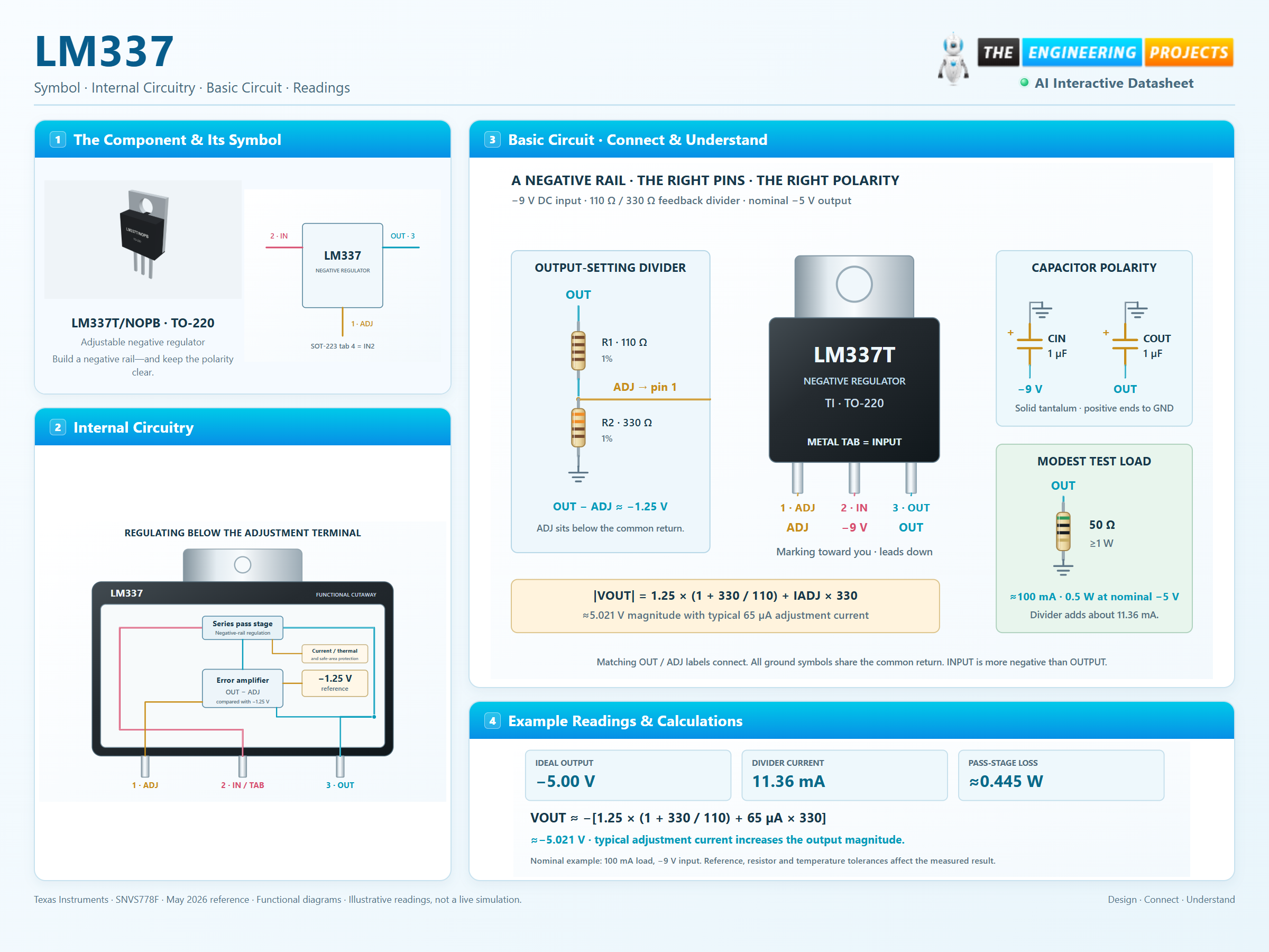
Follow the labeled connections and functional stages
3 stages · Explore one step at a time
The feedback loop maintains OUT minus ADJ near −1.25 V.
110 Ω from OUT to ADJ and 330 Ω from ADJ to ground give a nominal output magnitude of 5 V.
The divider draws about 11.36 mA. Fit the required output capacitor, positive end toward ground, and calculate the pass-stage loss.
A physical TO-220 package with the correct input tab and capacitor polarity.
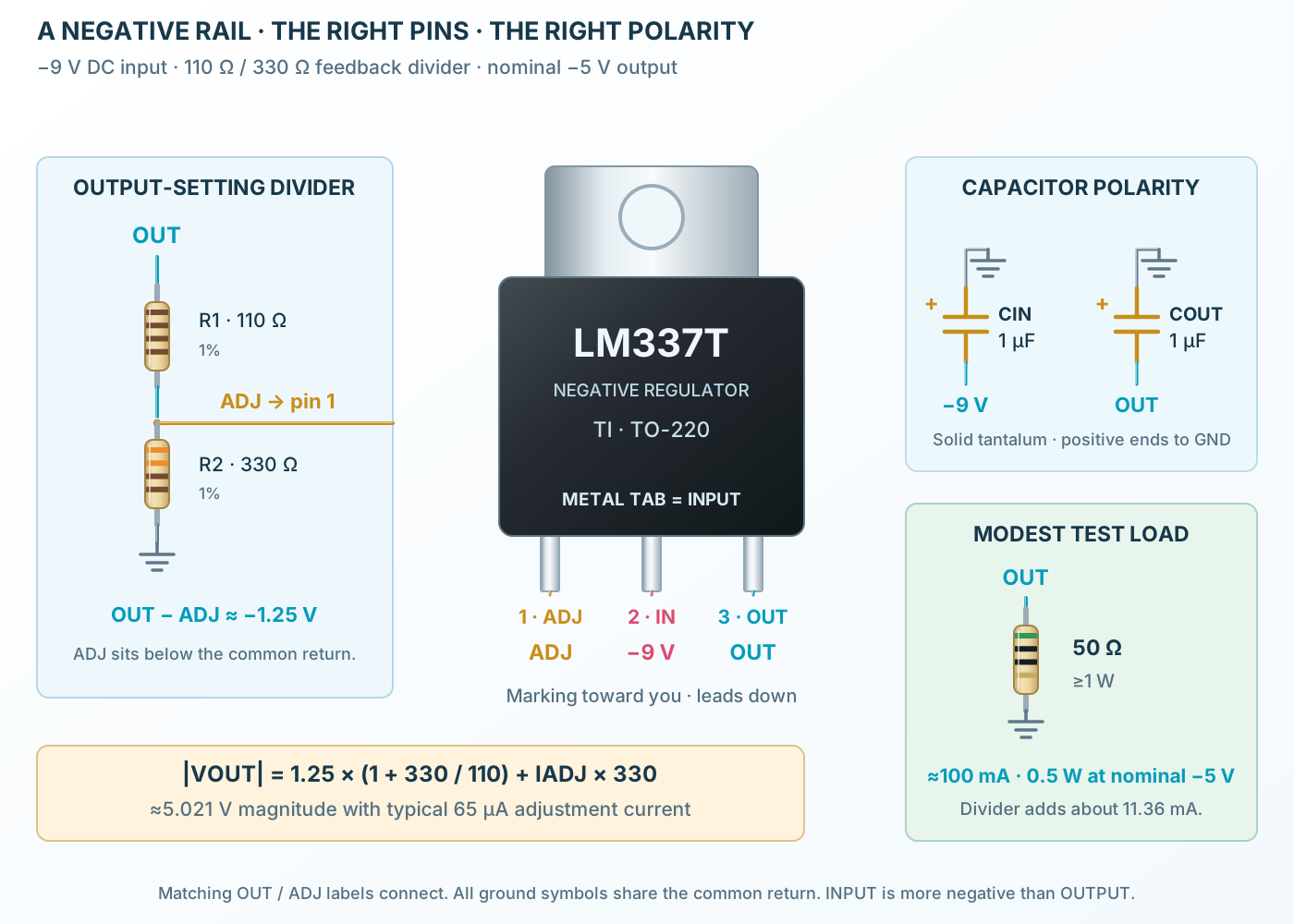
Follow the component values and pin connections
The middle lead and metal tab are negative IN; the right lead is OUT.
Use 110 Ω OUT-to-ADJ and 330 Ω ADJ-to-ground.
Connect the positive ends of the input and output tantalum capacitors to the common return.
The negative-reference control loop inside the regulator body.
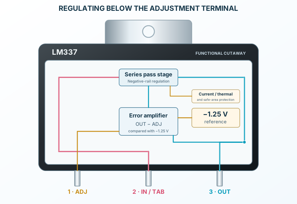
Select a stage to see its role and connections
Maintain OUT minus ADJ near −1.25 V.
Adjust the series stage between negative input and output.
Current, thermal and safe-area protection constrain abnormal operation.
Signal names, electrical functions and connection guidance
Scroll within the table to see all columns and rows.
| Pin | Signal | Type | Function & connection |
|---|---|---|---|
| ADJ | Floating adjustment terminal | The regulator holds OUTPUT approximately 1.25 V below ADJ.Connection guidanceConnect R1 from OUT to ADJ and R2 from ADJ to the common return. ADJ is not ground. Adjustment current flows into this terminal. | |
| IN | Negative input and metal tab | Accepts a negative supply more negative than the required output. The TO-220 tab and SOT-223 tab 4 are also IN.Connection guidanceConnect −9 V in the example; keep the live input tab isolated from grounded metal. This pin assignment differs from positive LM317/LM350 regulators. | |
| OUT | Regulated negative output | Supplies the load at a controlled negative voltage relative to the common return.Connection guidanceConnect R1, the load and the required output capacitor here. Polarized output capacitors have their positive end at the common return, not at OUT. | |
| IN / TAB | SOT-223 input tab | The broad SOT-223 contact is internally connected to input lead 2.Connection guidanceConnect to the negative input copper and provide an adequate thermal path. This is a separate physical contact on the same IN node; it is not ground. |
No pins match these filters. Try another signal name or reset the filters.
TI LM337-N electrical column
Scroll within the table to see all columns and rows.
| Parameter | Value | Conditions / notes |
|---|---|---|
| Nominal output adjustment | −1.25 to −37 V | With adequate differential voltage, loading and cooling |
| TO-220 order range | 0–125°C junction | LM337T/NOPB |
| SOT-223 order range | −40–125°C junction | LM337IMP/NOPB; do not extend the 0–125°C electrical table implicitly |
| Reference at 25°C | −1.213 / −1.25 / −1.287 V | Manufacturer MIN / TYP / MAX signed entries |
| Reference over stated LM337-N range | −1.20 / −1.25 / −1.30 V | 0–125°C; stated differential and load conditions |
| Adjustment-pin current | 65 µA typical; 100 µA maximum | Flows into ADJ |
| Adjustment current change | 2 µA typical; 5 µA maximum | 10 mA–IMAX; 3–40 V differential; 25°C |
No specifications match. Try a parameter name or a unit.
Electrical test baseline: 5 V input-output differential and 0.5 A load for TO-220/SOT-223, unless specified. Observe the source power conditions.
Constant-junction pulse measurements
Scroll within the table to see all columns and rows.
| Parameter | Value | Conditions / notes |
|---|---|---|
| Line regulation at 25°C | 0.01%/V typical; 0.04%/V maximum | 3–40 V differential; 10 mA load |
| Line regulation over stated range | 0.02%/V typical; 0.07%/V maximum | 3–40 V differential |
| Load regulation at 25°C | 0.3% typical; 1% maximum | 10 mA–IMAX |
| Load regulation over stated range | 0.3% typical; 1.5% maximum | Constant-junction test conditions |
| Thermal regulation | 0.003%/W typical; 0.04%/W maximum | 10 ms pulse; 25°C |
| Ripple rejection without CADJ | 60 dB typical | −10 V output; 120 Hz |
| Ripple rejection with 10 µF CADJ | 66 dB minimum; 77 dB typical | −10 V output; 120 Hz |
| Output noise | 0.003% of output typical | RMS; 10 Hz–10 kHz; 25°C |
No specifications match. Try a parameter name or a unit.
Typical values are not guaranteed extremes.
Current capability depends on voltage drop
Scroll within the table to see all columns and rows.
| Parameter | Value | Conditions / notes |
|---|---|---|
| Minimum load at ≤40 V differential | 2.5 mA typical; 10 mA maximum | Guarantee minimum current to maintain regulation |
| Minimum load at ≤10 V differential | 1.5 mA typical; 6 mA maximum | Manufacturer test condition |
| Current limit at ≤15 V differential | 1.5 / 2.2 / 3.7 A | Minimum / typical / maximum; DCY and NDE within power limits |
| Current limit at 40 V differential | 0.15 A minimum; 0.4 A typical | 25°C; safe-area limit reduces available current |
| Example divider | 1.25 / 110 ≈11.36 mA | Contributes to total output current |
| Divider lower bound | 1.20 / 111.1 ≈10.80 mA | 110 Ω at +1% and 1.20 V reference magnitude |
No specifications match. Try a parameter name or a unit.
A 1.5 A class regulator cannot supply full current at every differential voltage or without cooling.
Negative rails reverse the polarized capacitor orientation
Scroll within the table to see all columns and rows.
| Parameter | Value | Conditions / notes |
|---|---|---|
| Required output capacitor | 1 µF solid tantalum or 10 µF aluminum electrolytic | Required for stability; close to OUT and return |
| Input bypass | 1 µF solid tantalum | Required if more than 4 inches from the supply filter; used locally here |
| Positive capacitor terminals | Common return / GND | Negative ends connect to negative IN or OUT |
| Optional adjustment bypass | Improves ripple rejection | Evaluate discharge protection when added |
| Output discharge diode | Review when CL exceeds 20 µF | Source protection circuit diverts discharge during input short |
| Adjustment discharge diode | Review with CADJ >10 µF and output magnitude >25 V | Follow the source protection circuit |
| Example output capacitor | 1 µF solid tantalum, suitably voltage-rated | An arbitrary ceramic substitute is not assumed |
No specifications match. Try a parameter name or a unit.
The common return is the more positive node in this circuit.
Manufacturer thermal metrics · mounting matters
Scroll within the table to see all columns and rows.
| Parameter | Value | Conditions / notes |
|---|---|---|
| TO-220 θJA reference | 22.9°C/W | SNVS778F test-board metric; not a universal bare-package value |
| SOT-223 θJA reference | 58.3°C/W | Board copper and mounting strongly affect actual results |
| TO-220 θJC(bottom) | 1°C/W | Manufacturer package metric |
| Live tab | IN in both packages | SOT-223 contact 4 is connected to pin 2 |
| Nominal pass loss | (9 − 5) × (0.100 + 0.01136) ≈0.445 W | At 100 mA load plus divider |
| Absolute differential limit | 40 V | Stress limit; use operating headroom and power constraints |
| Internal protection | Current, thermal and safe-area limiting | Not a substitute for normal thermal design |
No specifications match. Try a parameter name or a unit.
Use the correct case/interface/heatsink or board model when estimating junction temperature.
−9 V input · 110 Ω / 330 Ω divider
Scroll within the table to see all columns and rows.
| Parameter | Value | Conditions / notes |
|---|---|---|
| R1 from OUT3 to ADJ1 | 110 Ω, 1% | Divider current about 11.36 mA |
| R2 from ADJ1 to GND | 330 Ω, 1% | R2/R1 = 3 |
| Ideal output | −1.25 × (1 + 330/110) = −5.00 V | Before adjustment current and tolerance |
| Typical IADJ correction | −65 µA × 330 Ω = −21.45 mV | Nominal result approximately −5.021 V |
| Load | 50 Ω, at least 1 W | Between GND and OUT; about 100 mA / 0.5 W |
| Input headroom | Approximately 4 V magnitude | −9 V input, −5 V output |
| Common return | Supply return, R2, load and capacitor positive ends | No dedicated ground pin on the IC |
No specifications match. Try a parameter name or a unit.
Nominal calculations; verify the actual loaded voltage and temperatures.
LM337T/NOPB · TO-220
Scroll within the table to see all columns and rows.
| Parameter | Value | Conditions / notes |
|---|---|---|
| TO-220 front-view lead order | 1 ADJ; 2 IN; 3 OUT | Marking toward you; leads down |
| SOT-223 top-view contacts | 1 ADJ; 2 IN; 3 OUT; 4 IN tab | Three narrow leads opposite a broad input tab |
| Selected pitch | 2.54 mm | See physical pin map and footprint |
| Selected operating range | 0–125°C operating junction; tab = IN | Package-specific note |
| Output versus tab | OUT is pin 3; tab is IN | Do not use a positive-regulator tab assumption |
| Storage | −65 to +150°C | Unpowered storage |
No specifications match. Try a parameter name or a unit.
Original package illustrations and reviewed starting footprints; verify the purchased part and assembly rules.
No matching rowsTry a pin name, parameter, unit or test condition, or reset the filters.
Supply operational amplifiers and analog circuits that require a negative rail.
Manufacturer application guideCombine separate positive and negative regulators around a shared return.
Manufacturer application guideStudy minimum load, feedback, stability capacitors and thermal limits with a modest DC load.
Manufacturer application guideFind LM337 in the Components Library to place its schematic symbol and connect its pins.
Reference page · circuit simulation model not yet availableOpen ProTech