LM338T5 A adjustable positive regulator
Set a positive rail—and account for minimum load, transient current and heat.
LM338T is a three-terminal adjustable positive linear regulator in a TO-220 package. Its floating reference is typically 1.24 V between OUTPUT and ADJUST; two resistors set a nominal output in the 1.2–32 V range when sufficient headroom and minimum load are provided. The device is specified for 5 A with suitable cooling and safe-area conditions. Its time-dependent current limit allows a specified 7 A minimum peak during the stated 0.5 ms test, while 12 A is only a typical limit. Sustained high differential voltage reduces the available current. This page follows TI SNVS771D for LM338T/NOPB. Front-view leads are ADJUST 1, OUTPUT 2 and INPUT 3; the silver mounting tab is OUTPUT. A modest 9 V input, 110 Ω / 330 Ω divider and 50 Ω load illustrate approximately 4.96 V before adjustment current and tolerances, with about 0.45 W pass-stage loss.
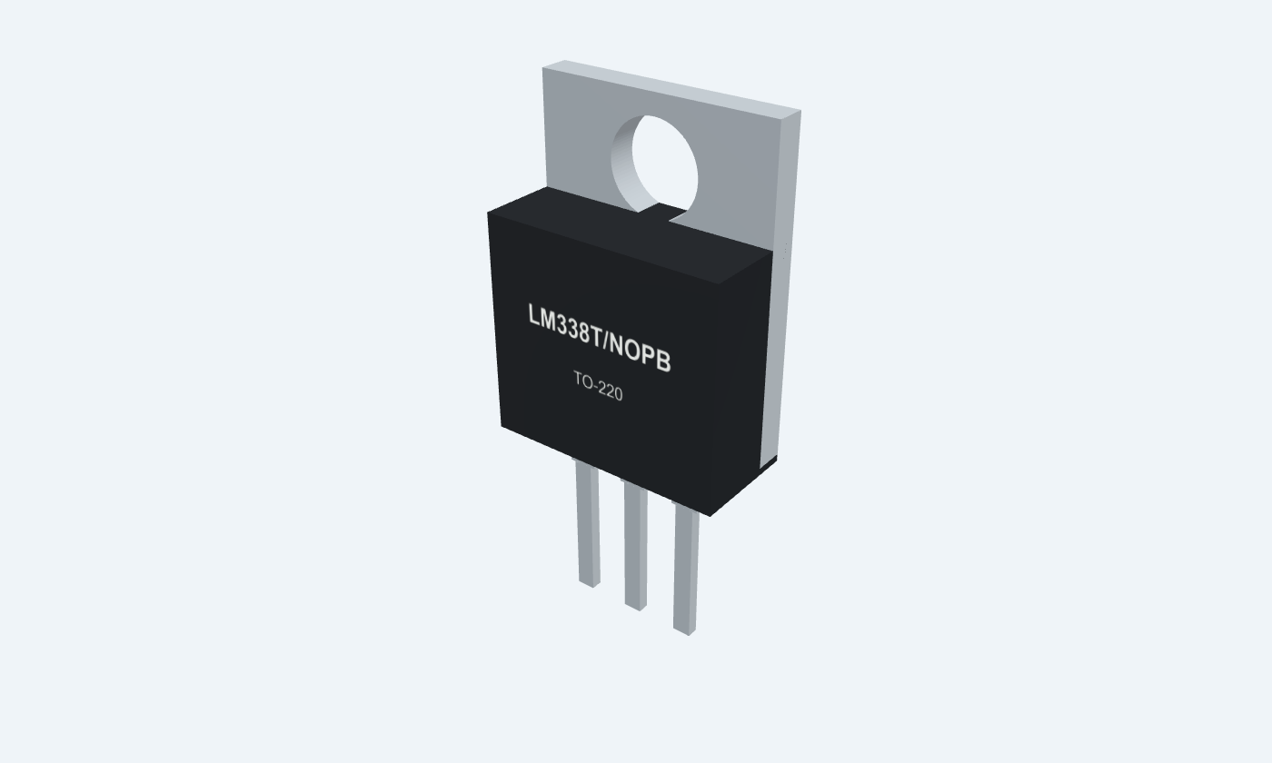

3Physical pins
LM338T/NOPBTO-220
Manufacturer-referencedTexas Instruments
Pin diagram
Select a pin to explore its connection
Highlight
LM338TTO-220Front view · marking toward you · ADJ1, OUT2, IN3
Click a lead or use the arrow keys. Front view · marking toward you · ADJ1, OUT2, IN3
PIN 1 · Adjustment and feedback
Floating reference terminalADJUST
Function
The feedback loop holds OUTPUT approximately 1.24 V above ADJUST.
How to connect
Connect the junction of R1 from OUTPUT and R2 to the return.
Electrical note
This is not ground; adjustment-pin current contributes IADJ × R2 to output voltage.
PIN 2 · Regulated output
Regulated output and tabOUTPUT
Function
Supplies the external load and feedback divider. The metal tab is electrically connected to OUTPUT.
How to connect
Connect R1 close to this lead and return R2 near the load return.
Electrical note
A grounded heatsink needs appropriate electrical insulation from the live output tab.
PIN 3 · Supply
Unregulated inputINPUT
Function
Powers the series pass stage.
How to connect
Use +9 V in the example, with a local 0.1 µF bypass to the common return.
Electrical note
Recommended input-to-output differential is 3–40 V; electrical reference tests use 3–35 V. Allow margin from the 40 V absolute differential limit.
Key specifications
The error amplifier controls a series pass stage to hold OUT minus ADJ near 1.24 V. The divider sets output voltage; current, safe-area and thermal controls constrain overloads.
Typical reference1.24 V · OUT minus ADJ
Adjustment range1.2–32 V · adequate headroom required
Current class5 A · safe area and cooling apply
Operating junction0–125 °C · LM338
Package details
LM338T/NOPB · TO-220
| Property | Details |
|---|---|
| Manufacturer | Texas Instruments |
| Part number | LM338T/NOPB |
| Package | TO-220 |
| Connections | 3 pins |
| Mounting | Through-hole |
| Lead pitch | 2.54 mm |
| Package code | NDE |
| Thermal reference | Output tab; use a suitable thermal path |
Operating reference
LM338 · TI SNVS771D
Manufacturer specifications 8 parameters
Scroll sideways to see all columns.
| Parameter | Value | Conditions / notes |
|---|---|---|
| Nominal adjustable output | 1.2–32 V | Subject to headroom, load and thermal limits |
| Operating junction | 0–125°C | LM338 rating; not ambient temperature |
| Reference voltage min / typ / max | 1.19 / 1.24 / 1.29 V | 3–35 V differential; 10 mA–5 A; 0–125°C |
| Adjustment current | 45 µA typical; 100 µA maximum | Flows out of ADJUST |
| Adjustment current change | 0.2 µA typical; 5 µA maximum | 10 mA–5 A; 3–35 V differential |
| Recommended differential | 3–40 V | Allow design margin; reference accuracy tests use 3–35 V |
| Absolute differential range | −0.3 to +40 V | Stress rating; not a regulation guarantee |
| Storage temperature | −65 to +150°C | Unpowered storage |
No specifications match. Try a parameter name or a unit.
Electrical limits apply under the manufacturer power and test conditions. Individual maxima cannot be combined.
Regulation and rejection
Values at constant junction temperature
Manufacturer specifications 8 parameters
Scroll sideways to see all columns.
| Parameter | Value | Conditions / notes |
|---|---|---|
| Line regulation, 25°C | 0.005 typical / 0.03 max. %/V | 3–35 V differential |
| Line regulation, 0–125°C | 0.02 typical / 0.06 max. %/V | Same differential range |
| Load regulation, 25°C | 0.1 typical / 0.5 max. % | 10 mA–5 A |
| Load regulation, 0–125°C | 0.3 typical / 1 max. % | 10 mA–5 A |
| Thermal regulation | 0.002 typical / 0.02 max. %/W | 20 ms pulse |
| Ripple rejection, no CADJ | 60 dB typical | 10 V output; 120 Hz |
| Ripple rejection, 10 µF CADJ | 60 dB minimum; 75 dB typical | 10 V output; 120 Hz |
| Output noise | 0.003% RMS typical | 10 Hz–10 kHz; percentage of output |
No specifications match. Try a parameter name or a unit.
The manufacturer load-regulation and temperature-stability rows omit printed percent unit symbols; these values are percentages as defined by the regulation parameters. Typical values are not guarantees.
Load and time-dependent limiting
Specified conditions matter
Manufacturer specifications 6 parameters
Scroll sideways to see all columns.
| Parameter | Value | Conditions / notes |
|---|---|---|
| Minimum load | 3.5 mA typical; 10 mA maximum required | 35 V differential; 0–125°C |
| DC current limit | 5 A minimum; 8 A typical | Differential ≤10 V; thermal/power restrictions |
| 0.5 ms peak limit | 7 A minimum; 12 A typical | Differential ≤10 V; not continuous output |
| Limit at 30 V differential | 1 A typical | No minimum listed in the LM338 row |
| Example divider current | 1.24 / 110 ≈11.27 mA | Nominal reference |
| Worst-case divider minimum | 1.19 / 111.1 ≈10.71 mA | 110 Ω at +1%; exceeds 10 mA requirement |
No specifications match. Try a parameter name or a unit.
Electrical specifications are limited to 25 W for TO-220 up to 15 V differential; above that internal protection imposes additional limits. This is not a no-heatsink power rating.
TO-220 thermal reference
NDE package · source test-board metrics
Manufacturer specifications 8 parameters
Scroll sideways to see all columns.
| Parameter | Value | Conditions / notes |
|---|---|---|
| RθJA | 22.9°C/W | Junction-to-ambient; standardized source conditions |
| RθJC(top) | 15.7°C/W | Junction to package top |
| RθJC(bot) | 0.7°C/W | Junction to bottom case / metal heat path |
| RθJB | 4.1°C/W | Junction-to-board |
| ψJT / ψJB | 2.1 / 4.1°C/W | Characterization parameters, not thermal resistances |
| Metal tab | Electrically OUTPUT | Insulate from a grounded heatsink as required |
| Example pass-stage loss | ≈0.446 W | (9−4.96) × (4.96/50 + 1.24/110) |
| 5 A with a 4 V drop | Approximately 20 W | Requires a designed thermal path and safe-area check |
No specifications match. Try a parameter name or a unit.
Do not apply the tab thermal path to the plastic top or use board θJA as a universal heatsink figure. Estimate junction temperature for the actual mounting.
Bypass and discharge paths
Manufacturer application guidance
Manufacturer specifications 6 parameters
Scroll sideways to see all columns.
| Parameter | Value | Conditions / notes |
|---|---|---|
| Input bypass | 0.1 µF disc or 1 µF solid tantalum | Near INPUT and common return |
| Output capacitor | 1 µF solid tantalum or 25 µF aluminum | Improves transient response; optional in suitable circuits |
| Small output capacitance | 500–5000 pF may ring | See source stability guidance |
| Adjustment bypass | 10 µF for improved ripple rejection | Optional; omitted in this example |
| Output discharge diode | No diode needed in stated ≤100 µF, ≤15 V case | Source section 7.2.1.2.3; evaluate externally driven rails separately |
| Adjustment discharge diode | No protection needed in stated ≤10 µF, ≤25 V case | Review larger stored charge and short-circuit paths |
No specifications match. Try a parameter name or a unit.
This example has 1 µF output capacitance near 5 V and no ADJ bypass; follow the manufacturer protection topology when conditions change.
Nominal near-5 V supply
9 V input · calculated example
Manufacturer specifications 7 parameters
Scroll sideways to see all columns.
| Parameter | Value | Conditions / notes |
|---|---|---|
| R1 / R2 | 110 Ω / 330 Ω, 1% | OUT-to-ADJ / ADJ-to-GND |
| Output before IADJ | 1.24 × (1+330/110) = 4.96 V | Uses typical reference |
| Typical IADJ contribution | 45 µA × 330 Ω = 14.85 mV | Output becomes about 4.97485 V |
| 50 Ω load | 99.2 mA; 0.492 W at 4.96 V | Use at least a 1 W resistor |
| Total nominal output current | 110.47 mA | Load plus divider; ignores small IADJ correction |
| Pass-stage dissipation | About 0.446 W | Nominal 9 V input |
| Reference/resistor bounds before IADJ | 4.689–5.238 V | 1.19–1.29 V reference and independent 1% divider extremes |
No specifications match. Try a parameter name or a unit.
Illustrative calculations, not a running circuit measurement. Check actual output and heating.
Physical pins and package
LM338T/NOPB · TO-220
Manufacturer specifications 6 parameters
Scroll sideways to see all columns.
| Parameter | Value | Conditions / notes |
|---|---|---|
| Front-view lead order | 1 ADJUST · 2 OUTPUT · 3 INPUT | Marking toward you, leads down |
| Tab | OUTPUT | Not ground |
| Lead pitch | 2.54 mm nominal | TI NDE0003B |
| Footprint | 1.30 mm finished holes; 2.00 mm pads | Original TEP vertical starting footprint |
| Other family package | LM338K metal TO-CAN | Different pin layout; not the selected footprint |
| SMD option | No SMD package verified in this TI sheet | No unrelated substitute is presented |
No specifications match. Try a parameter name or a unit.
Confirm the ordered part, actual lead forming, fabrication clearance and heatsink space.
Connections by function
Select a pin for its function, connection guidance and electrical notes.
Adjustment and feedback1 pin
Regulated output1 pin
Supply1 pin
LM338T at a glance
Follow the labeled connections and functional stages
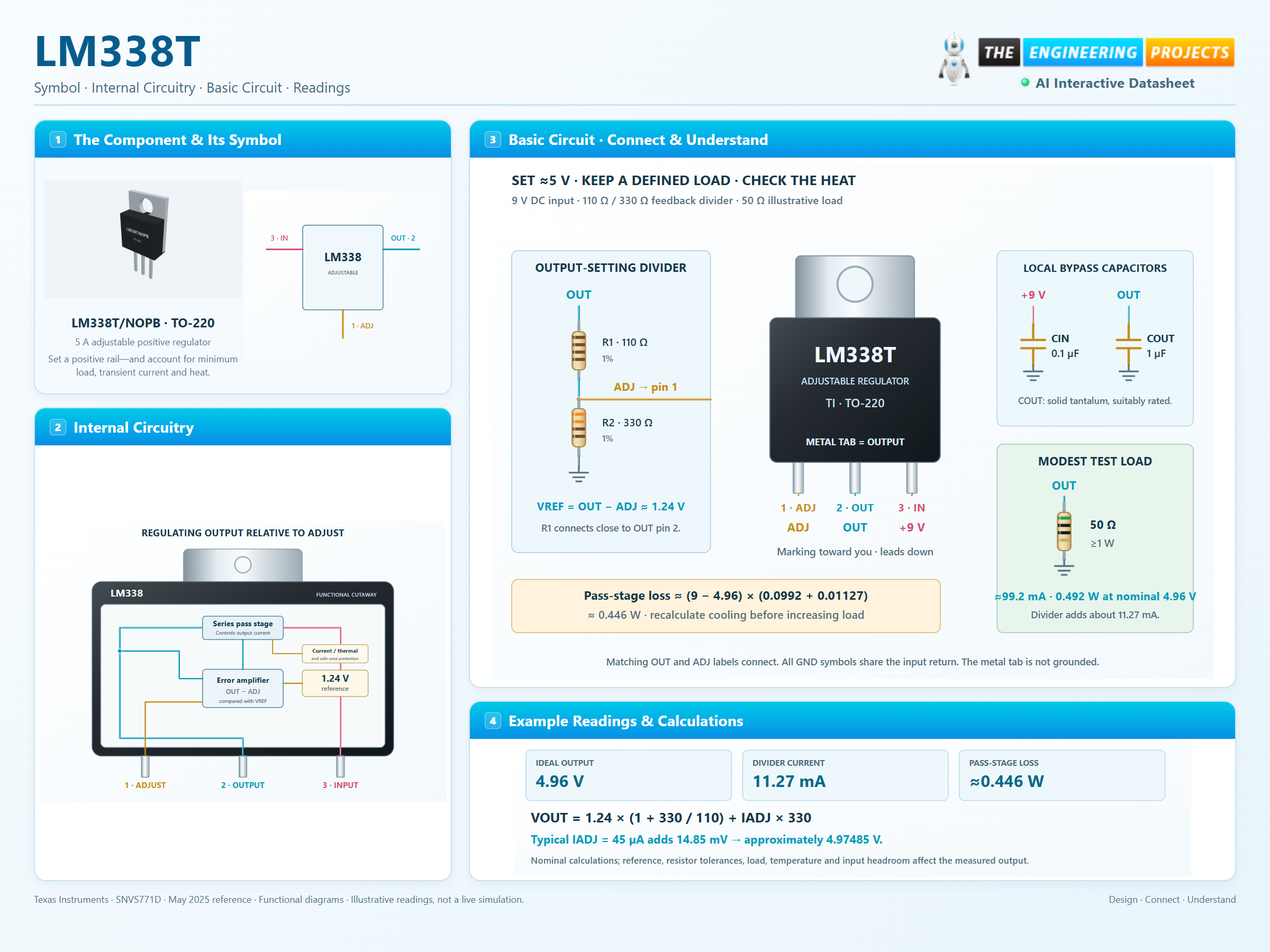
How it works
3 stages · Explore one step at a time
Establish the reference
The loop regulates OUTPUT relative to ADJUST; the package has no dedicated ground pin.
Set the ratio and minimum load
110 Ω from OUT to ADJ and 330 Ω from ADJ to ground give a ratio of three. Divider current is approximately 11.27 mA.
Check the thermal path
The 50 Ω load draws about 99.2 mA at 4.96 V. Include divider current when calculating dissipation and selecting a heatsink.
Step 1 of 3
LM338T in a circuit
Physical TO-220 regulator, feedback divider and a resistive load.
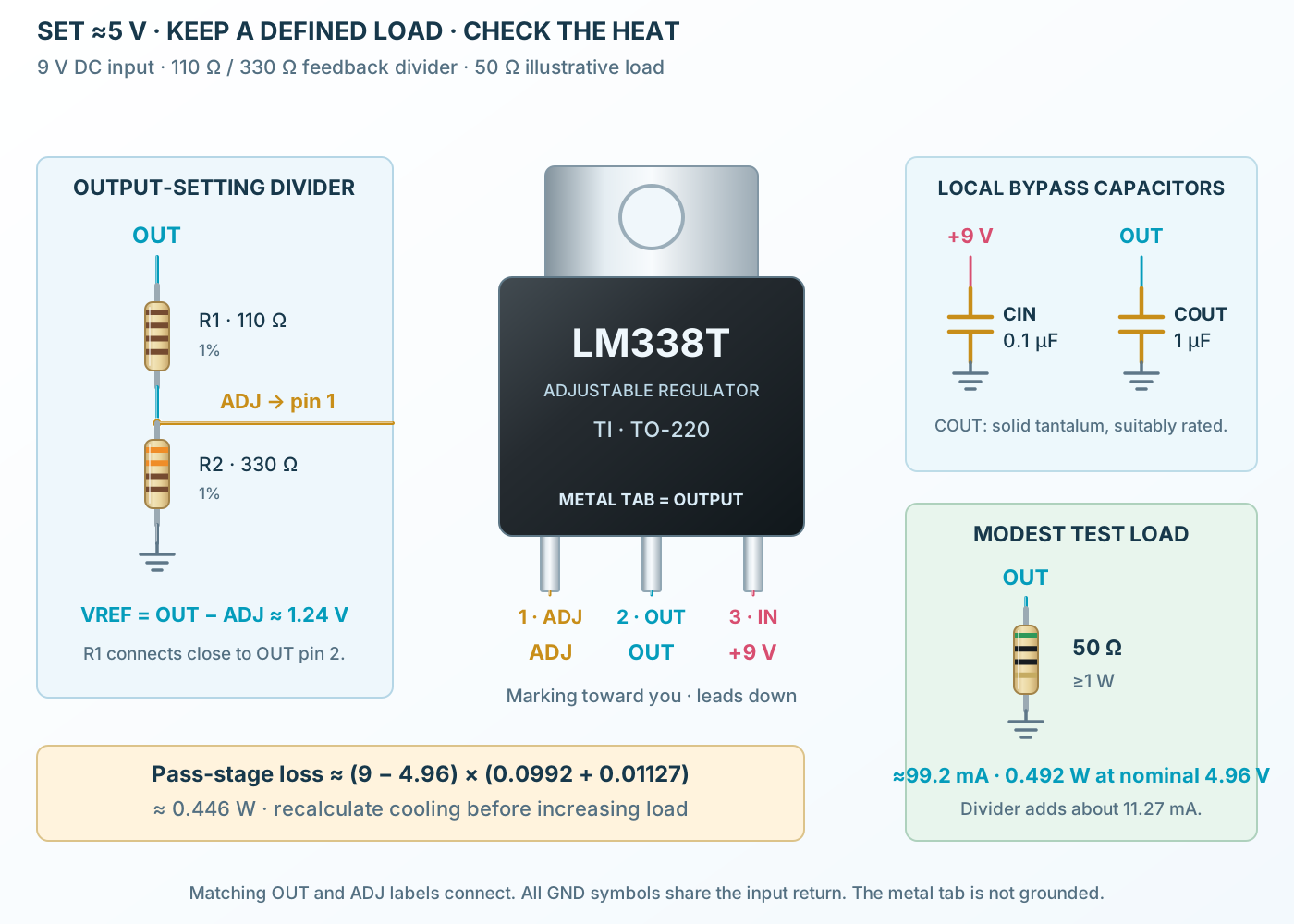
Connect it, step by step
Follow the component values and pin connections
Establish the reference
The loop regulates OUTPUT relative to ADJUST; the package has no dedicated ground pin.
Set the ratio and minimum load
110 Ω from OUT to ADJ and 330 Ω from ADJ to ground give a ratio of three. Divider current is approximately 11.27 mA.
Check the thermal path
The 50 Ω load draws about 99.2 mA at 4.96 V. Include divider current when calculating dissipation and selecting a heatsink.
Inside LM338T
A compact floating reference and pass-control loop inside the package.
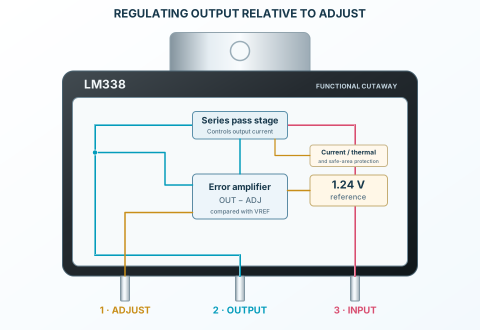
Explore the circuit
Select a stage to see its role and connections
Floating reference
The error amplifier compares OUT minus ADJ with approximately 1.24 V.
Series pass control
The pass transistor meters input current to the load.
Overload limits
Time-dependent current limiting, safe-area protection and thermal shutdown constrain abnormal stress.
Selected packageTO-220LM338T/NOPB
Physical connections3 pinsPackage-specific numbering
Reference collection8 tables49 parameters & pin functions
Pin reference
Signal names, electrical functions and connection guidance
Physical pin numbers3 pins
Scroll within the table to see all columns and rows.
| Pin | Signal | Type | Function & connection |
|---|---|---|---|
| ADJUST | Floating reference terminal | The feedback loop holds OUTPUT approximately 1.24 V above ADJUST.Connection guidanceConnect the junction of R1 from OUTPUT and R2 to the return. This is not ground; adjustment-pin current contributes IADJ × R2 to output voltage. | |
| OUTPUT | Regulated output and tab | Supplies the external load and feedback divider. The metal tab is electrically connected to OUTPUT.Connection guidanceConnect R1 close to this lead and return R2 near the load return. A grounded heatsink needs appropriate electrical insulation from the live output tab. | |
| INPUT | Unregulated input | Powers the series pass stage.Connection guidanceUse +9 V in the example, with a local 0.1 µF bypass to the common return. Recommended input-to-output differential is 3–40 V; electrical reference tests use 3–35 V. Allow margin from the 40 V absolute differential limit. |
No pins match these filters. Try another signal name or reset the filters.
Operating reference
LM338 · TI SNVS771D
Manufacturer-referenced values8 parameters
Scroll within the table to see all columns and rows.
| Parameter | Value | Conditions / notes |
|---|---|---|
| Nominal adjustable output | 1.2–32 V | Subject to headroom, load and thermal limits |
| Operating junction | 0–125°C | LM338 rating; not ambient temperature |
| Reference voltage min / typ / max | 1.19 / 1.24 / 1.29 V | 3–35 V differential; 10 mA–5 A; 0–125°C |
| Adjustment current | 45 µA typical; 100 µA maximum | Flows out of ADJUST |
| Adjustment current change | 0.2 µA typical; 5 µA maximum | 10 mA–5 A; 3–35 V differential |
| Recommended differential | 3–40 V | Allow design margin; reference accuracy tests use 3–35 V |
| Absolute differential range | −0.3 to +40 V | Stress rating; not a regulation guarantee |
| Storage temperature | −65 to +150°C | Unpowered storage |
No specifications match. Try a parameter name or a unit.
Electrical limits apply under the manufacturer power and test conditions. Individual maxima cannot be combined.
Regulation and rejection
Values at constant junction temperature
Manufacturer-referenced values8 parameters
Scroll within the table to see all columns and rows.
| Parameter | Value | Conditions / notes |
|---|---|---|
| Line regulation, 25°C | 0.005 typical / 0.03 max. %/V | 3–35 V differential |
| Line regulation, 0–125°C | 0.02 typical / 0.06 max. %/V | Same differential range |
| Load regulation, 25°C | 0.1 typical / 0.5 max. % | 10 mA–5 A |
| Load regulation, 0–125°C | 0.3 typical / 1 max. % | 10 mA–5 A |
| Thermal regulation | 0.002 typical / 0.02 max. %/W | 20 ms pulse |
| Ripple rejection, no CADJ | 60 dB typical | 10 V output; 120 Hz |
| Ripple rejection, 10 µF CADJ | 60 dB minimum; 75 dB typical | 10 V output; 120 Hz |
| Output noise | 0.003% RMS typical | 10 Hz–10 kHz; percentage of output |
No specifications match. Try a parameter name or a unit.
The manufacturer load-regulation and temperature-stability rows omit printed percent unit symbols; these values are percentages as defined by the regulation parameters. Typical values are not guarantees.
Load and time-dependent limiting
Specified conditions matter
Manufacturer-referenced values6 parameters
Scroll within the table to see all columns and rows.
| Parameter | Value | Conditions / notes |
|---|---|---|
| Minimum load | 3.5 mA typical; 10 mA maximum required | 35 V differential; 0–125°C |
| DC current limit | 5 A minimum; 8 A typical | Differential ≤10 V; thermal/power restrictions |
| 0.5 ms peak limit | 7 A minimum; 12 A typical | Differential ≤10 V; not continuous output |
| Limit at 30 V differential | 1 A typical | No minimum listed in the LM338 row |
| Example divider current | 1.24 / 110 ≈11.27 mA | Nominal reference |
| Worst-case divider minimum | 1.19 / 111.1 ≈10.71 mA | 110 Ω at +1%; exceeds 10 mA requirement |
No specifications match. Try a parameter name or a unit.
Electrical specifications are limited to 25 W for TO-220 up to 15 V differential; above that internal protection imposes additional limits. This is not a no-heatsink power rating.
TO-220 thermal reference
NDE package · source test-board metrics
Manufacturer-referenced values8 parameters
Scroll within the table to see all columns and rows.
| Parameter | Value | Conditions / notes |
|---|---|---|
| RθJA | 22.9°C/W | Junction-to-ambient; standardized source conditions |
| RθJC(top) | 15.7°C/W | Junction to package top |
| RθJC(bot) | 0.7°C/W | Junction to bottom case / metal heat path |
| RθJB | 4.1°C/W | Junction-to-board |
| ψJT / ψJB | 2.1 / 4.1°C/W | Characterization parameters, not thermal resistances |
| Metal tab | Electrically OUTPUT | Insulate from a grounded heatsink as required |
| Example pass-stage loss | ≈0.446 W | (9−4.96) × (4.96/50 + 1.24/110) |
| 5 A with a 4 V drop | Approximately 20 W | Requires a designed thermal path and safe-area check |
No specifications match. Try a parameter name or a unit.
Do not apply the tab thermal path to the plastic top or use board θJA as a universal heatsink figure. Estimate junction temperature for the actual mounting.
Bypass and discharge paths
Manufacturer application guidance
Manufacturer-referenced values6 parameters
Scroll within the table to see all columns and rows.
| Parameter | Value | Conditions / notes |
|---|---|---|
| Input bypass | 0.1 µF disc or 1 µF solid tantalum | Near INPUT and common return |
| Output capacitor | 1 µF solid tantalum or 25 µF aluminum | Improves transient response; optional in suitable circuits |
| Small output capacitance | 500–5000 pF may ring | See source stability guidance |
| Adjustment bypass | 10 µF for improved ripple rejection | Optional; omitted in this example |
| Output discharge diode | No diode needed in stated ≤100 µF, ≤15 V case | Source section 7.2.1.2.3; evaluate externally driven rails separately |
| Adjustment discharge diode | No protection needed in stated ≤10 µF, ≤25 V case | Review larger stored charge and short-circuit paths |
No specifications match. Try a parameter name or a unit.
This example has 1 µF output capacitance near 5 V and no ADJ bypass; follow the manufacturer protection topology when conditions change.
Nominal near-5 V supply
9 V input · calculated example
Manufacturer-referenced values7 parameters
Scroll within the table to see all columns and rows.
| Parameter | Value | Conditions / notes |
|---|---|---|
| R1 / R2 | 110 Ω / 330 Ω, 1% | OUT-to-ADJ / ADJ-to-GND |
| Output before IADJ | 1.24 × (1+330/110) = 4.96 V | Uses typical reference |
| Typical IADJ contribution | 45 µA × 330 Ω = 14.85 mV | Output becomes about 4.97485 V |
| 50 Ω load | 99.2 mA; 0.492 W at 4.96 V | Use at least a 1 W resistor |
| Total nominal output current | 110.47 mA | Load plus divider; ignores small IADJ correction |
| Pass-stage dissipation | About 0.446 W | Nominal 9 V input |
| Reference/resistor bounds before IADJ | 4.689–5.238 V | 1.19–1.29 V reference and independent 1% divider extremes |
No specifications match. Try a parameter name or a unit.
Illustrative calculations, not a running circuit measurement. Check actual output and heating.
Physical pins and package
LM338T/NOPB · TO-220
Manufacturer-referenced values6 parameters
Scroll within the table to see all columns and rows.
| Parameter | Value | Conditions / notes |
|---|---|---|
| Front-view lead order | 1 ADJUST · 2 OUTPUT · 3 INPUT | Marking toward you, leads down |
| Tab | OUTPUT | Not ground |
| Lead pitch | 2.54 mm nominal | TI NDE0003B |
| Footprint | 1.30 mm finished holes; 2.00 mm pads | Original TEP vertical starting footprint |
| Other family package | LM338K metal TO-CAN | Different pin layout; not the selected footprint |
| SMD option | No SMD package verified in this TI sheet | No unrelated substitute is presented |
No specifications match. Try a parameter name or a unit.
Confirm the ordered part, actual lead forming, fabrication clearance and heatsink space.
No matching rowsTry a pin name, parameter, unit or test condition, or reset the filters.
Adjustable DC rails
Set a positive rail with a divider and suitable thermal design.
Manufacturer application guideCurrent regulation
Use the manufacturer’s reference-resistor configuration to establish a current, within voltage and power limits.
Manufacturer application guideSupply experiments
Explore reference tolerances, minimum load, headroom and heat with a modest DC supply.
Manufacturer application guideTake it into ProTech
Find LM338T in the Components Library to place its schematic symbol and connect its pins.
Reference page · circuit simulation model not yet availableOpen ProTech