 BETA
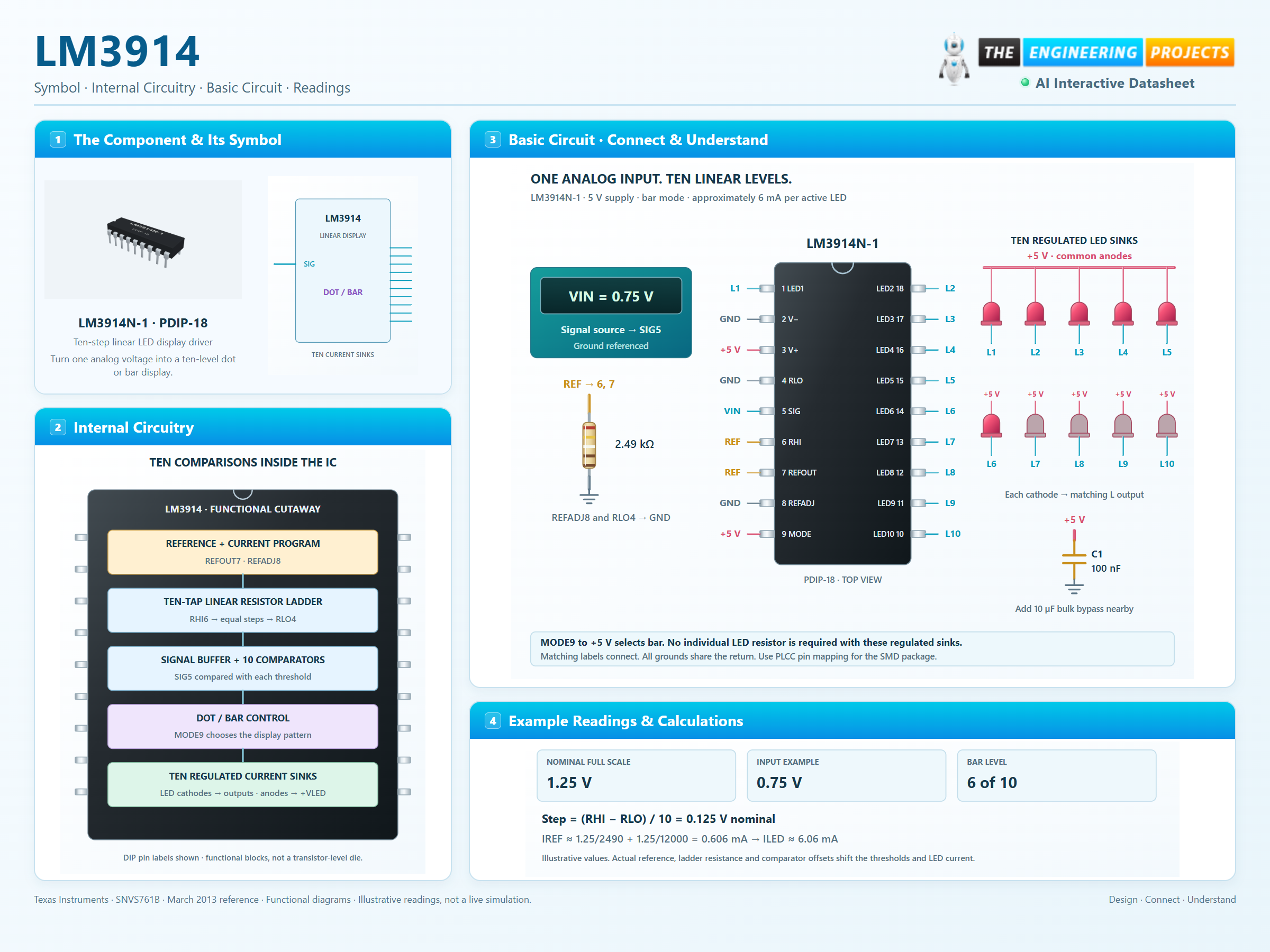
Ten-step linear LED display driver
LM3914 Working Principle
Learn how LM3914 works with an illustrated explanation and practical readings.
Package view
LM3914 at a glance
Follow the labeled connections and functional stages
How it works
3 stages · Explore one step at a time
Set the scale
RLO and RHI establish the ten-step comparison range.
Compare the input
The buffer distributes SIG to ten comparators connected to the ladder taps.
Drive the LEDs
Dot/bar logic selects current sinks; the reference load sets approximate brightness.
Step 1 of 3