MCP73831Single-cell linear charge controller
Follow a cell through precharge, constant current and constant voltage.
MCP73831 is a linear charger for one compatible lithium-ion or lithium-polymer cell. Its internal pass transistor manages reduced-current preconditioning, constant-current charging, constant-voltage regulation and charge termination without an external power transistor. This page selects the -2AC option: 4.20 V regulation, 10% precharge current and 7.5% termination current. A 10 kΩ programming resistor sets nominal 100 mA fast charge. The three-state STAT output indicates the charging phase; it is not a battery-percentage measurement. Both SOT-23-5 and DFN-8 packages are mapped, including the DFN duplicate power contacts and exposed ground pad. The example uses a regulated 5.2 V source and a compatible 4.2 V-charge cell. External cell protection, temperature supervision and power-path management must be provided when the application requires them.
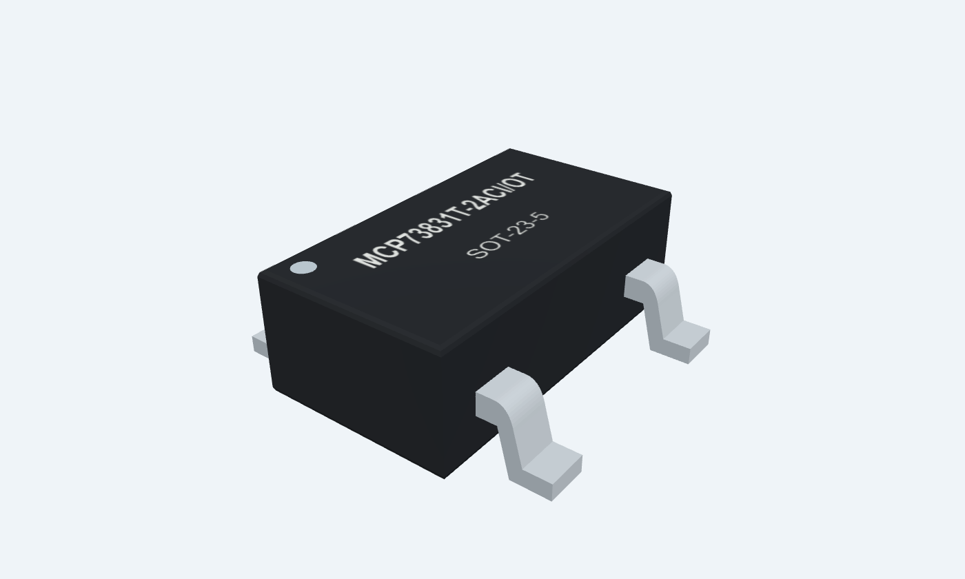
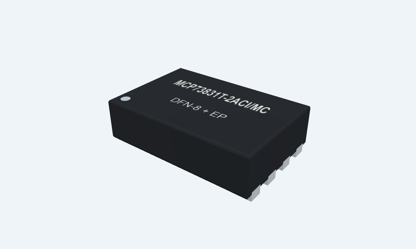

5Physical pins
MCP73831T-2ACI/OTSOT-23-5
Manufacturer-referencedMicrochip Technology
Pin diagram
Select a pin to explore its connection
Highlight
MCP73831SOT-23-5Top view rotated clockwise · three leads left, two right
MCP73831DFN-8 + EPTop view rotated clockwise · contact 9 is underneath, shown separately
Click a lead or use the arrow keys. Top view rotated clockwise · three leads left, two right
PIN 1 · Battery and status
Three-state charge indicationSTAT
Function
LOW during preconditioning, constant-current charging and constant-voltage charging; HIGH when charging completes; high impedance during shutdown or with no battery.
How to connect
An LED from the input supply through a resistor to STAT lights during charging.
Electrical note
MCP73831 has a driven HIGH state. Do not assume the open-drain behavior of MCP73832.
PIN 2 · Ground
Supply and battery returnVSS
Function
Common zero-volt reference for the charger, input source and cell.
How to connect
Join the input return, battery negative, bypass returns and programming resistor.
Electrical note
Connect the DFN exposed pad to this same ground potential.
PIN 3 · Battery and status
Charge-control outputVBAT
Function
The integrated pass transistor supplies regulated current and voltage to the positive battery terminal.
How to connect
Connect the compatible single-cell battery positive and at least 4.7 µF local bypass.
Electrical note
The selected -2 option regulates at 4.20 V; it is not suitable for a different cell charging voltage by assumption.
PIN 4 · Supply
Input supplyVDD
Function
Provides charger power from a regulated input source.
How to connect
Use 5.2 V in the reference example and at least 4.7 µF local bypass to VSS.
Electrical note
Recommended input has headroom above the cell regulation voltage; 7 V is an absolute stress limit.
PIN 5 · Charge programming
Charge-current programming and disablePROG
Function
A resistor to VSS programs the nominal fast-charge current. Floating PROG disables charging.
How to connect
10 kΩ gives nominal 100 mA; choose a current allowed by the cell manufacturer.
Electrical note
Preconditioning and termination currents track the programmed current and the factory option.
PIN 6 · Supply
Second DFN input contactVDD
Function
This physical DFN contact is the same supply node as the other VDD contact.
How to connect
Connect both VDD pads to the bypassed input supply.
Electrical note
Do not leave a power contact unconnected.
PIN 7 · Battery and status
Second DFN battery contactVBAT
Function
This physical DFN contact is the same charge-output node as the other VBAT contact.
How to connect
Connect both VBAT pads to battery positive and the local bypass.
Electrical note
The two contacts do not represent separate charging channels.
PIN 8 · Not connected
No connectionNC
Function
The manufacturer assigns no external electrical function to this DFN contact.
How to connect
Leave unconnected.
Electrical note
Do not use it as a routing junction.
PIN 9 · Ground
DFN exposed thermal padEP
Function
The underside metal pad is internally connected to VSS and must connect to ground on the PCB.
How to connect
Solder to a grounded thermal land; review copper, vias and stencil design.
Electrical note
This is contact 9 underneath the body, not an additional side lead.
Key specifications
Current is held near its programmed value until the cell reaches the regulation voltage. The charger then holds voltage while current tapers, terminating when the selected threshold is reached.
Selected charge voltage4.20 V · -2 option
Programmable fast charge15–500 mA nominal range
Specified ambient−40–85 °C
Example program resistor10 kΩ → 100 mA nominal
Package details
MCP73831T-2ACI/OT · SOT-23-5
| Property | Details |
|---|---|
| Manufacturer | Microchip Technology |
| Part number | MCP73831T-2ACI/OT |
| Package | SOT-23-5 |
| Connections | 5 pins |
| Mounting | SMD |
| Lead pitch | 0.95 mm |
| Package code | OT |
| Thermal reference | −40–85°C specified ambient; board-dependent cooling |
Supply and regulation
Selected MCP73831-2AC · conditions retained
Manufacturer specifications 7 parameters
Scroll sideways to see all columns.
| Parameter | Value | Conditions / notes |
|---|---|---|
| Input operating range | 3.75–6 V | Allow adequate headroom above the battery |
| Recommended input for -2 option | 4.50–6 V | Pin description: VREG + 0.3 V minimum |
| Reference test supply | 5.2 V | VREG + 1 V; example uses the same value |
| Regulated battery voltage | 4.168 / 4.200 / 4.232 V | Minimum / typical / maximum; -5–55°C, 10 mA output, 5.2 V input |
| Line regulation | 0.09%/V typical; 0.30%/V maximum | 5.2–6 V input; 10 mA output |
| Load regulation | 0.05% typical; 0.30% maximum | 10–50 mA; 5.2 V input |
| Specified ambient / operating junction | −40–85°C / −40–125°C | Do not extend narrower table conditions implicitly |
No specifications match. Try a parameter name or a unit.
Unless a row states otherwise, source limits use VREG + 1 V to 6 V and −40–85°C ambient; typical values use 25°C.
Set the charge current
IREG[mA] = 1000 / RPROG[kΩ]
Manufacturer specifications 7 parameters
Scroll sideways to see all columns.
| Parameter | Value | Conditions / notes |
|---|---|---|
| Programming resistor range | 2–67 kΩ | Source operating impedance range |
| 10 kΩ example | 100 mA nominal | 90–110 mA source limits at −5–55°C |
| 2 kΩ example | 500 mA by design equation | Source table gives 505 mA typical, 450–550 mA limits; design-assured |
| 67 kΩ example | About 15 mA nominal | Source table: 12.5 / 14.5 / 16.5 mA |
| Disable charging | Float PROG | Charge current stops; STAT becomes high impedance |
| Cell-current selection | Follow the specific cell manufacturer | Capacity alone is insufficient to choose a safe charge rate |
| RPROG tolerance | Adds to programmed-current error | Use a suitable precision resistor |
No specifications match. Try a parameter name or a unit.
Do not infer that every cell accepts the charger’s maximum programmed current.
The selected -2AC sequence
Factory options are not runtime settings
Manufacturer specifications 7 parameters
Scroll sideways to see all columns.
| Parameter | Value | Conditions / notes |
|---|---|---|
| Regulation voltage | 4.20 V | The -2 voltage code |
| Precharge current | 10% of fast-charge current | 7.5–12.5% source limits at −5–55°C |
| Precharge transition | 66.5% of VREG nominal | 64–69% limits; nominal 2.793 V for 4.20 V |
| Termination current | 7.5% of fast-charge current | 5.6–9.4% limits at −5–55°C |
| Automatic recharge | 96.5% of VREG nominal | 94–99% limits; nominal 4.053 V |
| 100 mA example thresholds | 10 mA precharge; 7.5 mA termination | Nominal values before tolerances |
| Other options | Different voltage, precharge or termination settings | Read the exact suffix; do not substitute family values |
No specifications match. Try a parameter name or a unit.
Charge time depends on the cell, starting state, current taper and thermal regulation.
Read STAT correctly
MCP73831 three-state output
Manufacturer specifications 7 parameters
Scroll sideways to see all columns.
| Parameter | Value | Conditions / notes |
|---|---|---|
| Preconditioning | LOW | Charging indicator LED can be on |
| Constant-current fast charge | LOW | Not a percentage-of-charge indication |
| Constant-voltage phase | LOW | Current tapers while regulation holds |
| Charge complete / standby | HIGH | This is driven HIGH on MCP73831 |
| Shutdown or no battery | High impedance | An unlit single LED cannot distinguish these from complete |
| Source / sink logic test | About 0.4 V typical drop at 4 mA | Use the full electrical limits for logic interfacing |
| Microcontroller connection | Observe output voltage and logic compatibility | Do not connect a 5 V STAT signal to a non-tolerant 3.3 V input |
No specifications match. Try a parameter name or a unit.
MCP73832 has an open-drain status output and a different complete-state indication.
A nominal 100 mA charger
SOT-23-5 example · one compatible cell
Manufacturer specifications 8 parameters
Scroll sideways to see all columns.
| Parameter | Value | Conditions / notes |
|---|---|---|
| Input supply | Regulated 5.2 V | VDD4 with common return at VSS2 |
| CIN and COUT | At least 4.7 µF each | Local low-ESR ceramic; account for DC-bias derating |
| RPROG | 10 kΩ to ground | PROG5; 100 mA nominal fast charge |
| Charge indicator | Input → 2.2 kΩ → LED anode; cathode → STAT1 | Lights while STAT is LOW |
| Cell positive / negative | VBAT3 / common ground | Single cell specified for 4.20 V termination |
| Cell nominal voltage | Typically described as 3.7 V | Nominal label is not the full-charge setting |
| Pass-stage heat at 3.0 V cell | (5.2 − 3.0) × 0.1 = 0.22 W | Before bias-current losses; constant-current phase |
| Attached load | Not shown in this charger-only example | A system load can affect termination; use appropriate power-path design |
No specifications match. Try a parameter name or a unit.
This IC is not a complete protected battery pack or a power-path controller.
Thermal behavior and protection
Heat can reduce the actual charge current
Manufacturer specifications 8 parameters
Scroll sideways to see all columns.
| Parameter | Value | Conditions / notes |
|---|---|---|
| SOT-23 θJA reference | 230°C/W | Four-layer standard board; larger copper can improve it |
| DFN θJA reference | 76°C/W | Source minimum-copper condition on four-layer board |
| Thermal regulation | Reduces charge current as the die heats | Do not assume programmed current is maintained continuously |
| Thermal shutdown | 150°C typical | About 10°C hysteresis |
| Input absolute maximum | 7 V | Stress limit, not the 6 V operating maximum |
| Battery reverse leakage | 2 µA maximum in specified disabled conditions | No input / below UVLO / PROG floating |
| Cell temperature | No dedicated thermistor input | External supervision is needed where required by the cell or application |
| Battery fault protection | Not a substitute for a pack protection circuit | Provide required over-discharge, short-circuit and cell safeguards |
No specifications match. Try a parameter name or a unit.
At 0.22 W and 230°C/W, a simple reference estimate gives about 51°C rise; actual board conditions and regulation change the result.
Physical package mapping
MCP73831T-2ACI/OT · SOT-23-5
Manufacturer specifications 7 parameters
Scroll sideways to see all columns.
| Parameter | Value | Conditions / notes |
|---|---|---|
| SOT-23-5 pins | 1 STAT; 2 VSS; 3 VBAT; 4 VDD; 5 PROG | Five external leads; no separate exposed pad |
| DFN-8 pins | 1/2 VDD; 3/4 VBAT; 5 STAT; 6 VSS; 7 NC; 8 PROG | Connect both contacts of each power node |
| DFN contact 9 | Exposed pad, internally VSS | Must connect to the ground plane |
| SOT body / pitch | 1.60 × 2.90 mm / 0.95 mm | Shown rotated into left/right pin banks |
| DFN body / pitch | 2 × 3 × 0.9 mm nominal / 0.50 mm | Shown rotated clockwise; bottom pad identified separately |
| SOT marking family | KD + trace code for selected -2AC option | Illustration labels identify the order rather than reproduce a lot code |
| DFN marking family | AAE + trace codes for selected -2AC option | See manufacturer marking table |
No specifications match. Try a parameter name or a unit.
Original reviewed footprints are assembly starting points; check the purchased package and production design rules.
Connections by function
Select a pin for its function, connection guidance and electrical notes.
Battery and status2 pins
Ground1 pin
Supply1 pin
Charge programming1 pin
Supply2 pins
Battery and status3 pins
Ground2 pins
Not connected1 pin
Charge programming1 pin
MCP73831 at a glance
Follow the labeled connections and functional stages
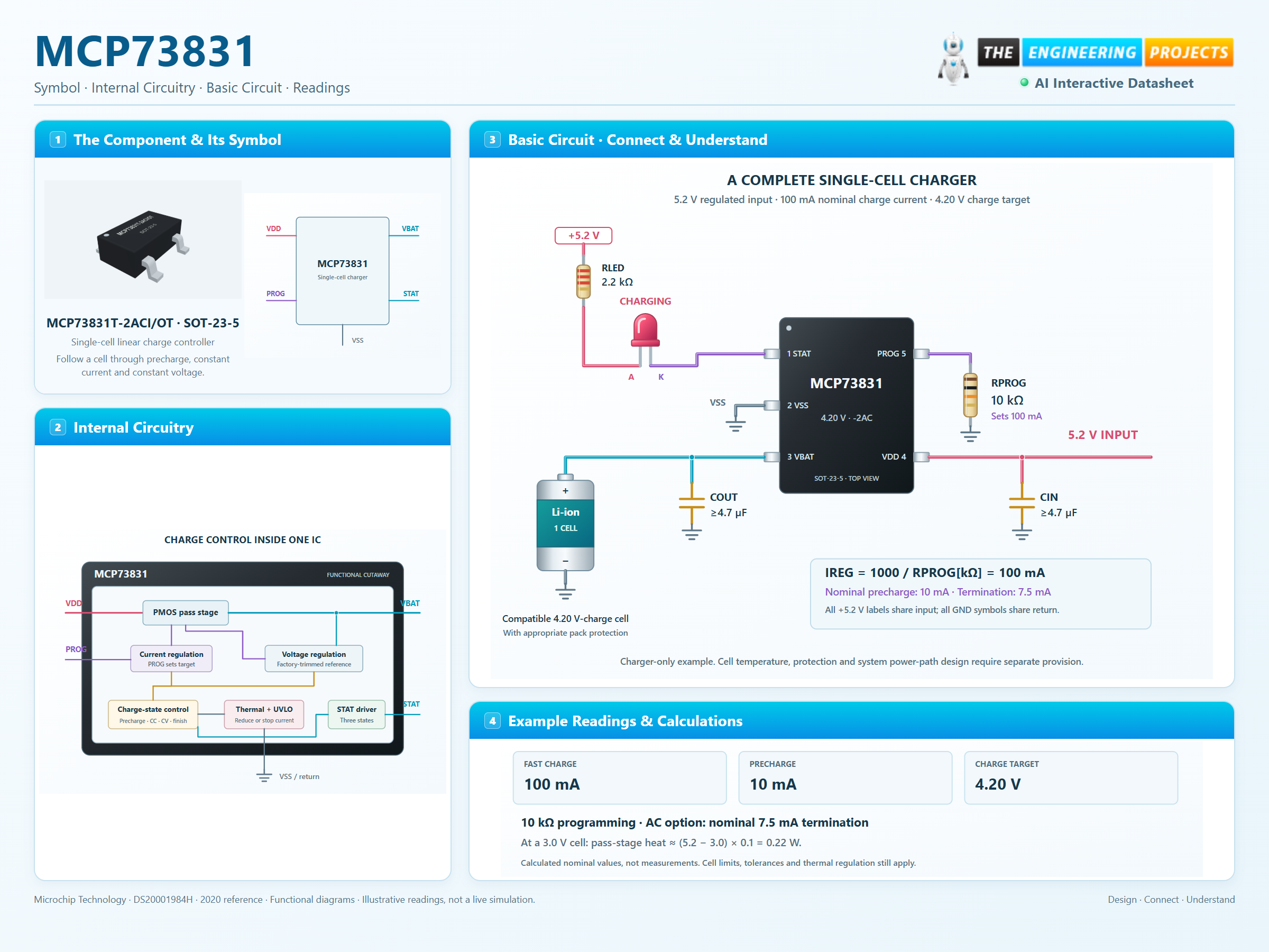
How it works
3 stages · Explore one step at a time
Qualify and precondition
With valid input and a detected cell below the precharge threshold, apply a reduced current.
Charge at constant current
The PROG resistor sets nominal current; thermal regulation can reduce it.
Hold voltage, then finish
At 4.20 V the current tapers. AC-option termination occurs at nominal 7.5% of the programmed fast-charge current.
Step 1 of 3
MCP73831 in a circuit
Physical SOT-23-5 connections and a modest 100 mA example.
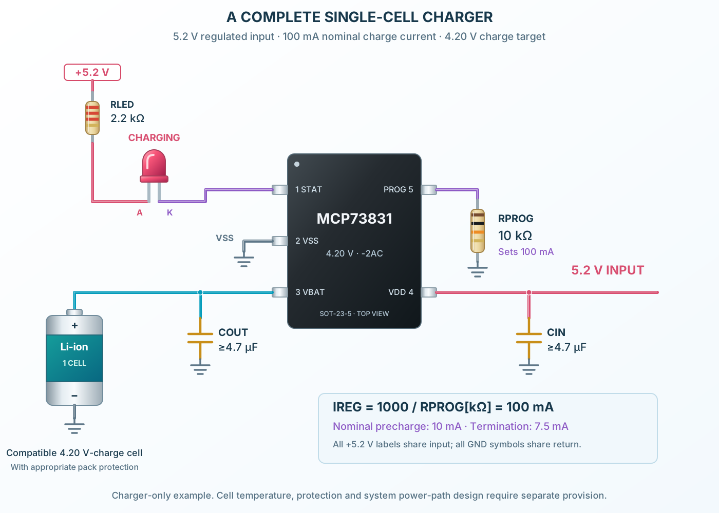
Connect it, step by step
Follow the component values and pin connections
Bypass both power nodes
Place at least 4.7 µF at VDD and VBAT, close to the IC.
Set a suitable current
10 kΩ from PROG to VSS gives nominal 100 mA.
Read the charge indication
The input-powered LED lights while STAT sinks current; it is not a fuel gauge.
Inside MCP73831
Charge control inside a compact IC outline.
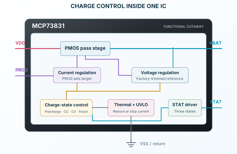
Explore the circuit
Select a stage to see its role and connections
Sense current and voltage
Current and voltage loops control the integrated pass transistor.
Advance the charge phase
Factory options set the precharge, termination and recharge thresholds.
Report and protect
STAT indicates the phase; thermal control can reduce or suspend charging.
Selected packageSOT-23-5MCP73831T-2ACI/OT
Physical connections5 pinsPackage-specific numbering
Reference collection8 tables51 parameters & pin functions
Pin reference
Signal names, electrical functions and connection guidance
Physical pin numbers5 pins
Scroll within the table to see all columns and rows.
| Pin | Signal | Type | Function & connection |
|---|---|---|---|
| STAT | Three-state charge indication | LOW during preconditioning, constant-current charging and constant-voltage charging; HIGH when charging completes; high impedance during shutdown or with no battery.Connection guidanceAn LED from the input supply through a resistor to STAT lights during charging. MCP73831 has a driven HIGH state. Do not assume the open-drain behavior of MCP73832. | |
| VSS | Supply and battery return | Common zero-volt reference for the charger, input source and cell.Connection guidanceJoin the input return, battery negative, bypass returns and programming resistor. Connect the DFN exposed pad to this same ground potential. | |
| VBAT | Charge-control output | The integrated pass transistor supplies regulated current and voltage to the positive battery terminal.Connection guidanceConnect the compatible single-cell battery positive and at least 4.7 µF local bypass. The selected -2 option regulates at 4.20 V; it is not suitable for a different cell charging voltage by assumption. | |
| VDD | Input supply | Provides charger power from a regulated input source.Connection guidanceUse 5.2 V in the reference example and at least 4.7 µF local bypass to VSS. Recommended input has headroom above the cell regulation voltage; 7 V is an absolute stress limit. | |
| PROG | Charge-current programming and disable | A resistor to VSS programs the nominal fast-charge current. Floating PROG disables charging.Connection guidance10 kΩ gives nominal 100 mA; choose a current allowed by the cell manufacturer. Preconditioning and termination currents track the programmed current and the factory option. | |
| VDD | Second DFN input contact | This physical DFN contact is the same supply node as the other VDD contact.Connection guidanceConnect both VDD pads to the bypassed input supply. Do not leave a power contact unconnected. | |
| VBAT | Second DFN battery contact | This physical DFN contact is the same charge-output node as the other VBAT contact.Connection guidanceConnect both VBAT pads to battery positive and the local bypass. The two contacts do not represent separate charging channels. | |
| NC | No connection | The manufacturer assigns no external electrical function to this DFN contact.Connection guidanceLeave unconnected. Do not use it as a routing junction. | |
| EP | DFN exposed thermal pad | The underside metal pad is internally connected to VSS and must connect to ground on the PCB.Connection guidanceSolder to a grounded thermal land; review copper, vias and stencil design. This is contact 9 underneath the body, not an additional side lead. |
No pins match these filters. Try another signal name or reset the filters.
Supply and regulation
Selected MCP73831-2AC · conditions retained
Manufacturer-referenced values7 parameters
Scroll within the table to see all columns and rows.
| Parameter | Value | Conditions / notes |
|---|---|---|
| Input operating range | 3.75–6 V | Allow adequate headroom above the battery |
| Recommended input for -2 option | 4.50–6 V | Pin description: VREG + 0.3 V minimum |
| Reference test supply | 5.2 V | VREG + 1 V; example uses the same value |
| Regulated battery voltage | 4.168 / 4.200 / 4.232 V | Minimum / typical / maximum; -5–55°C, 10 mA output, 5.2 V input |
| Line regulation | 0.09%/V typical; 0.30%/V maximum | 5.2–6 V input; 10 mA output |
| Load regulation | 0.05% typical; 0.30% maximum | 10–50 mA; 5.2 V input |
| Specified ambient / operating junction | −40–85°C / −40–125°C | Do not extend narrower table conditions implicitly |
No specifications match. Try a parameter name or a unit.
Unless a row states otherwise, source limits use VREG + 1 V to 6 V and −40–85°C ambient; typical values use 25°C.
Set the charge current
IREG[mA] = 1000 / RPROG[kΩ]
Manufacturer-referenced values7 parameters
Scroll within the table to see all columns and rows.
| Parameter | Value | Conditions / notes |
|---|---|---|
| Programming resistor range | 2–67 kΩ | Source operating impedance range |
| 10 kΩ example | 100 mA nominal | 90–110 mA source limits at −5–55°C |
| 2 kΩ example | 500 mA by design equation | Source table gives 505 mA typical, 450–550 mA limits; design-assured |
| 67 kΩ example | About 15 mA nominal | Source table: 12.5 / 14.5 / 16.5 mA |
| Disable charging | Float PROG | Charge current stops; STAT becomes high impedance |
| Cell-current selection | Follow the specific cell manufacturer | Capacity alone is insufficient to choose a safe charge rate |
| RPROG tolerance | Adds to programmed-current error | Use a suitable precision resistor |
No specifications match. Try a parameter name or a unit.
Do not infer that every cell accepts the charger’s maximum programmed current.
The selected -2AC sequence
Factory options are not runtime settings
Manufacturer-referenced values7 parameters
Scroll within the table to see all columns and rows.
| Parameter | Value | Conditions / notes |
|---|---|---|
| Regulation voltage | 4.20 V | The -2 voltage code |
| Precharge current | 10% of fast-charge current | 7.5–12.5% source limits at −5–55°C |
| Precharge transition | 66.5% of VREG nominal | 64–69% limits; nominal 2.793 V for 4.20 V |
| Termination current | 7.5% of fast-charge current | 5.6–9.4% limits at −5–55°C |
| Automatic recharge | 96.5% of VREG nominal | 94–99% limits; nominal 4.053 V |
| 100 mA example thresholds | 10 mA precharge; 7.5 mA termination | Nominal values before tolerances |
| Other options | Different voltage, precharge or termination settings | Read the exact suffix; do not substitute family values |
No specifications match. Try a parameter name or a unit.
Charge time depends on the cell, starting state, current taper and thermal regulation.
Read STAT correctly
MCP73831 three-state output
Manufacturer-referenced values7 parameters
Scroll within the table to see all columns and rows.
| Parameter | Value | Conditions / notes |
|---|---|---|
| Preconditioning | LOW | Charging indicator LED can be on |
| Constant-current fast charge | LOW | Not a percentage-of-charge indication |
| Constant-voltage phase | LOW | Current tapers while regulation holds |
| Charge complete / standby | HIGH | This is driven HIGH on MCP73831 |
| Shutdown or no battery | High impedance | An unlit single LED cannot distinguish these from complete |
| Source / sink logic test | About 0.4 V typical drop at 4 mA | Use the full electrical limits for logic interfacing |
| Microcontroller connection | Observe output voltage and logic compatibility | Do not connect a 5 V STAT signal to a non-tolerant 3.3 V input |
No specifications match. Try a parameter name or a unit.
MCP73832 has an open-drain status output and a different complete-state indication.
A nominal 100 mA charger
SOT-23-5 example · one compatible cell
Manufacturer-referenced values8 parameters
Scroll within the table to see all columns and rows.
| Parameter | Value | Conditions / notes |
|---|---|---|
| Input supply | Regulated 5.2 V | VDD4 with common return at VSS2 |
| CIN and COUT | At least 4.7 µF each | Local low-ESR ceramic; account for DC-bias derating |
| RPROG | 10 kΩ to ground | PROG5; 100 mA nominal fast charge |
| Charge indicator | Input → 2.2 kΩ → LED anode; cathode → STAT1 | Lights while STAT is LOW |
| Cell positive / negative | VBAT3 / common ground | Single cell specified for 4.20 V termination |
| Cell nominal voltage | Typically described as 3.7 V | Nominal label is not the full-charge setting |
| Pass-stage heat at 3.0 V cell | (5.2 − 3.0) × 0.1 = 0.22 W | Before bias-current losses; constant-current phase |
| Attached load | Not shown in this charger-only example | A system load can affect termination; use appropriate power-path design |
No specifications match. Try a parameter name or a unit.
This IC is not a complete protected battery pack or a power-path controller.
Thermal behavior and protection
Heat can reduce the actual charge current
Manufacturer-referenced values8 parameters
Scroll within the table to see all columns and rows.
| Parameter | Value | Conditions / notes |
|---|---|---|
| SOT-23 θJA reference | 230°C/W | Four-layer standard board; larger copper can improve it |
| DFN θJA reference | 76°C/W | Source minimum-copper condition on four-layer board |
| Thermal regulation | Reduces charge current as the die heats | Do not assume programmed current is maintained continuously |
| Thermal shutdown | 150°C typical | About 10°C hysteresis |
| Input absolute maximum | 7 V | Stress limit, not the 6 V operating maximum |
| Battery reverse leakage | 2 µA maximum in specified disabled conditions | No input / below UVLO / PROG floating |
| Cell temperature | No dedicated thermistor input | External supervision is needed where required by the cell or application |
| Battery fault protection | Not a substitute for a pack protection circuit | Provide required over-discharge, short-circuit and cell safeguards |
No specifications match. Try a parameter name or a unit.
At 0.22 W and 230°C/W, a simple reference estimate gives about 51°C rise; actual board conditions and regulation change the result.
Physical package mapping
MCP73831T-2ACI/OT · SOT-23-5
Manufacturer-referenced values7 parameters
Scroll within the table to see all columns and rows.
| Parameter | Value | Conditions / notes |
|---|---|---|
| SOT-23-5 pins | 1 STAT; 2 VSS; 3 VBAT; 4 VDD; 5 PROG | Five external leads; no separate exposed pad |
| DFN-8 pins | 1/2 VDD; 3/4 VBAT; 5 STAT; 6 VSS; 7 NC; 8 PROG | Connect both contacts of each power node |
| DFN contact 9 | Exposed pad, internally VSS | Must connect to the ground plane |
| SOT body / pitch | 1.60 × 2.90 mm / 0.95 mm | Shown rotated into left/right pin banks |
| DFN body / pitch | 2 × 3 × 0.9 mm nominal / 0.50 mm | Shown rotated clockwise; bottom pad identified separately |
| SOT marking family | KD + trace code for selected -2AC option | Illustration labels identify the order rather than reproduce a lot code |
| DFN marking family | AAE + trace codes for selected -2AC option | See manufacturer marking table |
No specifications match. Try a parameter name or a unit.
Original reviewed footprints are assembly starting points; check the purchased package and production design rules.
No matching rowsTry a pin name, parameter, unit or test condition, or reset the filters.
Small portable products
Charge a compatible single cell at a current suited to its specification.
Manufacturer application guideCharge-status interfaces
Use the three-state output to distinguish charging from standby with suitable logic.
Manufacturer application guideThermal design exercises
Compare SOT and DFN cooling and observe how current regulation responds to heat.
Manufacturer application guideTake it into ProTech
Find MCP73831 in the Components Library to place its schematic symbol and connect its pins.
Reference page · circuit simulation model not yet availableOpen ProTech