Real View
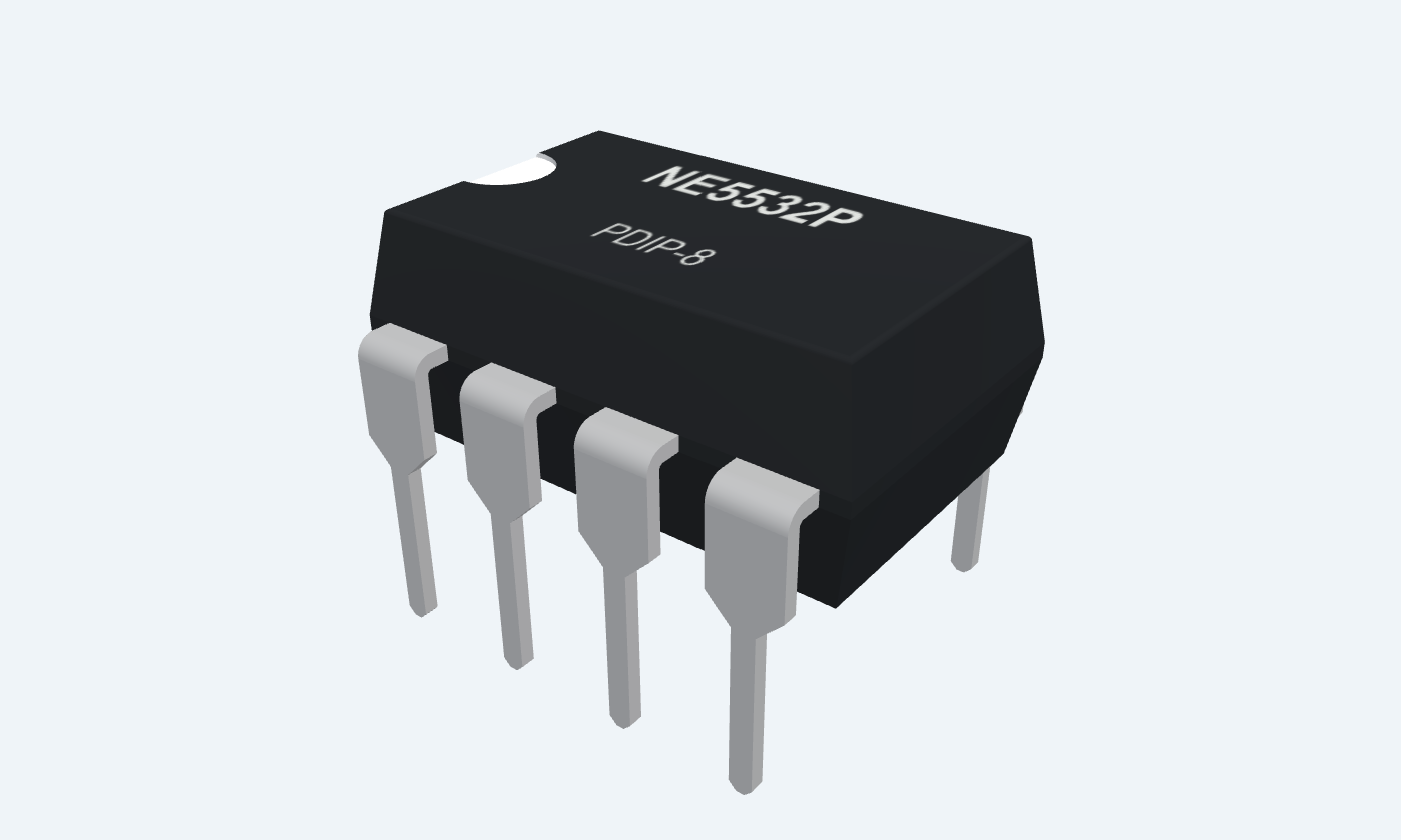
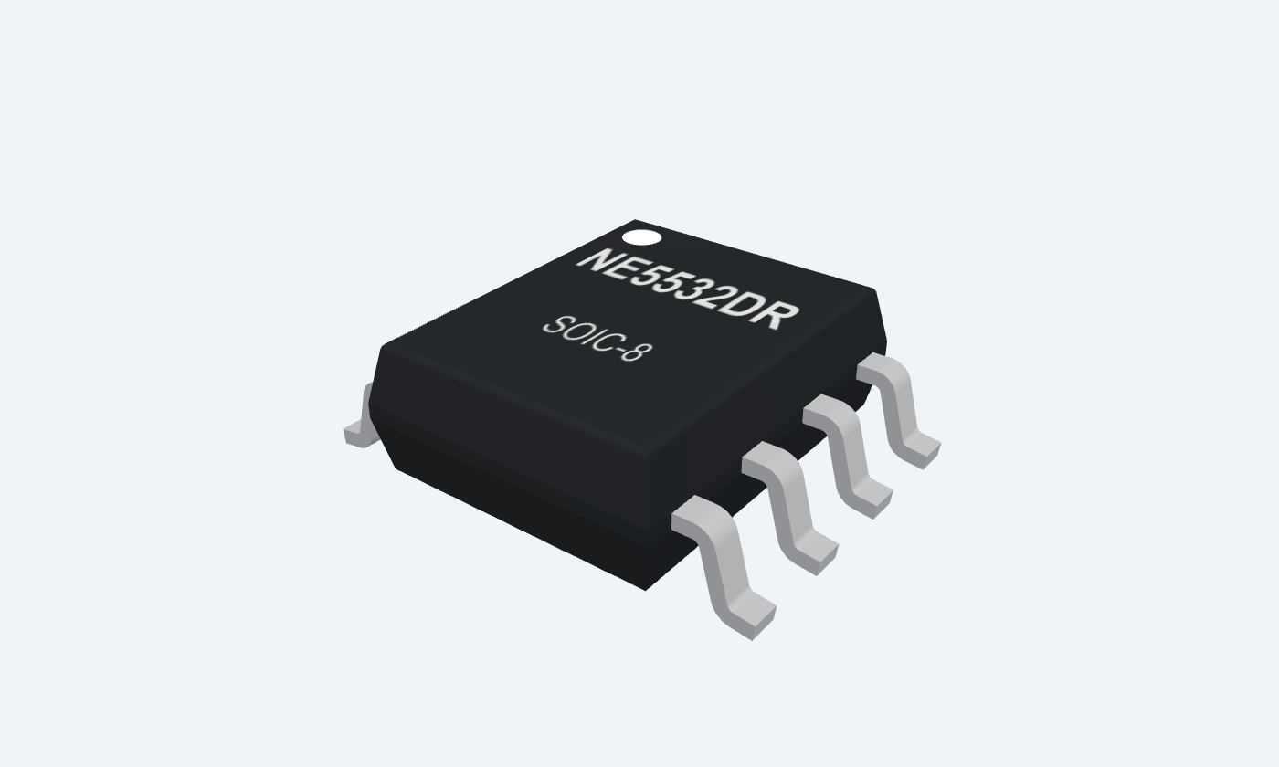
Low-noise gain for two analog signal paths.
NE5532 contains two low-noise bipolar-input operational amplifiers. It is widely used for analog and audio stages where voltage noise, drive capability and predictable feedback behavior matter. Our example uses one channel at a gain of three and the other as a buffer. Both channels receive 0.50 V, giving ideal DC outputs of 1.50 V and 0.50 V from ±15 V rails. The reference uses TI NE5532 commercial-grade PDIP-8 and SOIC-8 parts. Input bias current and source resistance deserve attention: low voltage noise does not mean negligible input-current error.
Select a pin to explore its connection
Click a lead or use the arrow keys. Top view
Channel A output.
Return to IN1− through 20 kΩ; connect a high-impedance meter.
Channel A negative-feedback node.
Join 20 kΩ from OUT1 and 10 kΩ to signal ground.
Channel A signal input.
Apply VIN = 0.50 V relative to the 0 V midpoint.
Negative rail shared by both amplifiers.
Connect −15 V; bypass locally to 0 V with 100 nF.
Channel B signal input.
Connect to the same VIN in the illustrated follower.
Channel B feedback input.
Connect directly to OUT2 pin 7.
Channel B output.
Connect to IN2−; leave unloaded or use a high-impedance instrument.
Positive rail shared by both amplifiers.
Connect +15 V; bypass locally to 0 V with 100 nF.
Low voltage noise is useful for low-impedance signal sources. Include bias-current and current-noise effects when choosing resistors.
NE5532P · PDIP-8
| Property | Details |
|---|---|
| Manufacturer | Texas Instruments |
| Part number | NE5532P |
| Package | PDIP-8 |
| Connections | 8 pins |
| Mounting | Through-hole |
| Lead pitch | 2.54 mm |
| Package code | dip |
| Thermal reference | Board and package dependent; see manufacturer data |
TI NE5532 commercial grade
Scroll sideways to see all columns.
| Parameter | Value | Conditions / notes |
|---|---|---|
| Positive supply | +5 to +15 V | Relative to signal midpoint |
| Negative supply | −5 to −15 V | Relative to signal midpoint |
| Ambient temperature | 0 to +70°C | NE5532 / NE5532A |
| Example rails | ±15 V | Local bypass on each rail |
| SA grade | −40 to +85°C | Separate ordering family; not the illustrated NE part |
No specifications match. Try a parameter name or a unit.
The ±18 V absolute maximum is a stress limit, not the recommended operating supply.
±15 V · 25°C unless stated
Scroll sideways to see all columns.
| Parameter | Value | Conditions / notes |
|---|---|---|
| Input offset voltage | 0.5 mV typical; 4 mV maximum | 5 mV maximum over temperature |
| Input bias current | 200 nA typical; 800 nA maximum | 1 µA maximum over temperature |
| Input offset current | 10 nA typical; 150 nA maximum | 200 nA maximum over temperature |
| Common-mode range | ±12 V minimum; ±13 V typical | ±15 V supply |
| Total supply current | 6 mA typical; 16 mA maximum | Both channels; no output load |
| Open-loop gain | 100 V/mV typical; 25 minimum | RL ≥ 2 kΩ; VO = ±10 V |
No specifications match. Try a parameter name or a unit.
Use resistor values that balance loading, noise and bias-current error.
±15 V · 25°C
Scroll sideways to see all columns.
| Parameter | Value | Conditions / notes |
|---|---|---|
| Unity-gain bandwidth | 12 MHz typical | Manufacturer B1 characteristic |
| Slew rate | 5 V/µs typical | Unity gain |
| Voltage noise at 1 kHz | 5 nV/√Hz typical | NE5532 |
| Voltage noise at 30 Hz | 8 nV/√Hz typical | NE5532 |
| Current noise at 1 kHz | 0.7 pA/√Hz typical | Source resistance converts this to voltage noise |
| Current noise at 30 Hz | 2.7 pA/√Hz typical | Low-frequency input-current noise |
No specifications match. Try a parameter name or a unit.
Noise densities are not total RMS noise; integrate over the circuit’s effective bandwidth.
Feedback, signal and loading
Scroll sideways to see all columns.
| Parameter | Value | Conditions / notes |
|---|---|---|
| Large differential input | Limit input current | Internal protection diodes conduct around a 0.6 V difference |
| Unused channel | Give it defined feedback | The example uses channel B as an unloaded follower |
| Supply bypass | 100 nF per rail, close to IC | Add board-level bulk capacitance as required |
| Capacitive loads | Check stability | Do not assume an arbitrary cable can be driven directly |
| Short-circuit current | 38 mA typical test characteristic | Not a recommended continuous operating current |
No specifications match. Try a parameter name or a unit.
Keep signal returns away from high-current paths and check the actual output load.
±15 V rails · 0 V signal reference
Scroll sideways to see all columns.
| Parameter | Value | Conditions / notes |
|---|---|---|
| Input VIN | 0.50 V | Pins 3 and 5; common signal ground |
| Channel A feedback | 20 kΩ | OUT1 pin 1 to IN1− pin 2 |
| Channel A ground resistor | 10 kΩ | IN1− pin 2 to 0 V |
| Channel A ideal output | 1.50 V | 0.50 × (1 + 20 / 10) |
| Channel B feedback | Direct connection | OUT2 pin 7 to IN2− pin 6 |
| Channel B ideal output | 0.50 V | Unity-gain follower |
| Bypass capacitors | 100 nF per rail | Each supply rail to the 0 V midpoint |
No specifications match. Try a parameter name or a unit.
The 0 V reference is not the negative supply pin. Keep both rail-bypass loops short.
NE5532P · PDIP-8
Scroll sideways to see all columns.
| Parameter | Value | Conditions / notes |
|---|---|---|
| Lead pitch | 2.54 mm | Through-hole |
| Channel A | OUT1 1; IN1− 2; IN1+ 3 | Independent feedback loop |
| Channel B | IN2+ 5; IN2− 6; OUT2 7 | Independent feedback loop |
| Supply | V− 4; V+ 8 | Shared by both channels |
| Package orientation | Top view; pin 1 at the marker | Counterclockwise numbering |
No specifications match. Try a parameter name or a unit.
This dual-amplifier pinout differs from single amplifiers such as TL081 or LM741.
Select a pin for its function, connection guidance and electrical notes.
Follow the labeled connections and functional stages
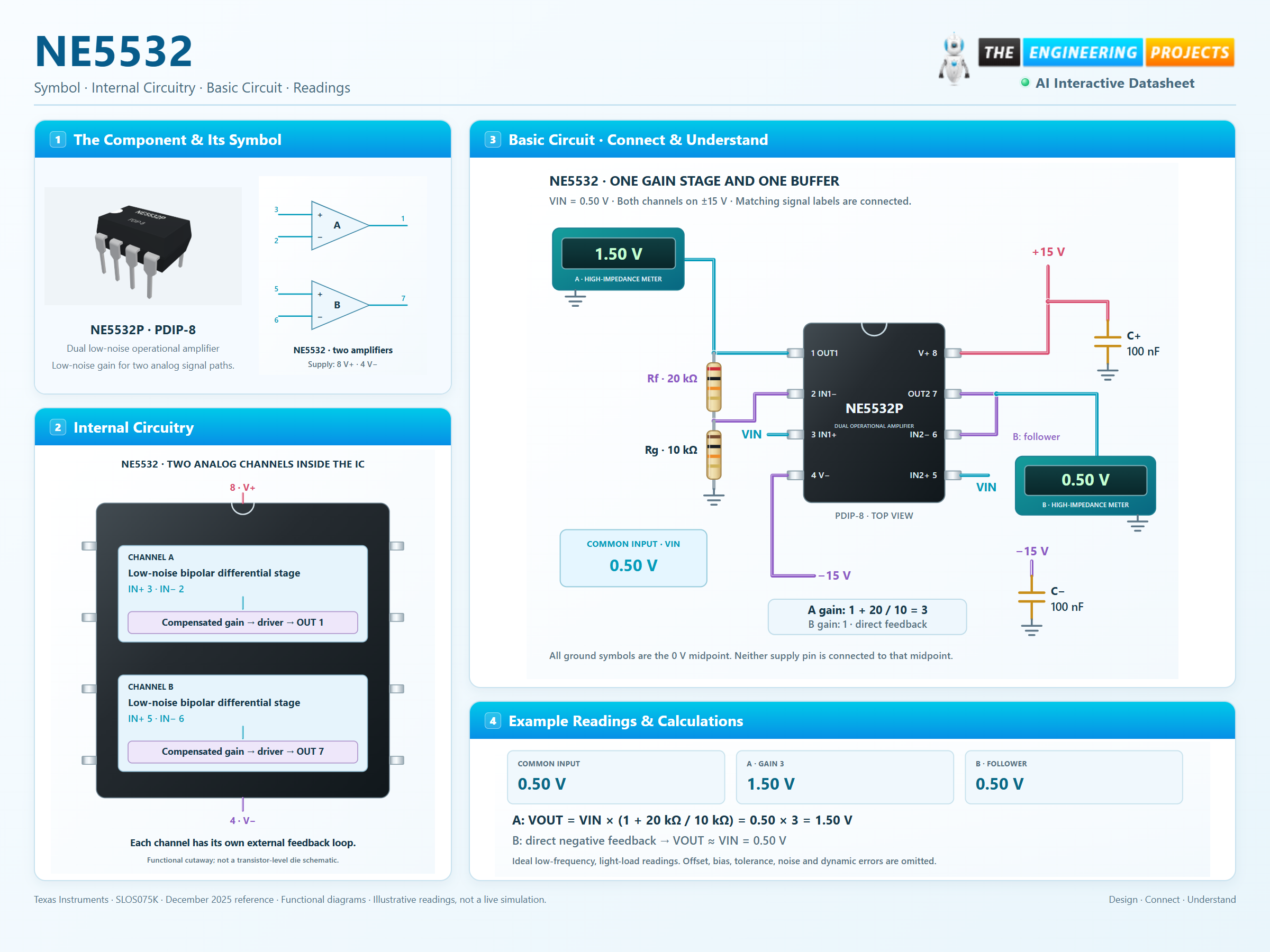
3 stages · Explore one step at a time
The bipolar differential inputs offer low voltage noise, but draw bias current. The resulting error depends on source resistance and the feedback network.
Channel A uses 20 kΩ feedback and 10 kΩ to the 0 V midpoint, giving a gain of three. Channel B directly feeds its output back to its negative input, giving unity gain.
With a 0.50 V input, the ideal outputs are 1.50 V and 0.50 V. Real output also depends on input offset, resistor accuracy, loading, noise and signal frequency.
A gain-of-three channel beside a unity-gain follower.
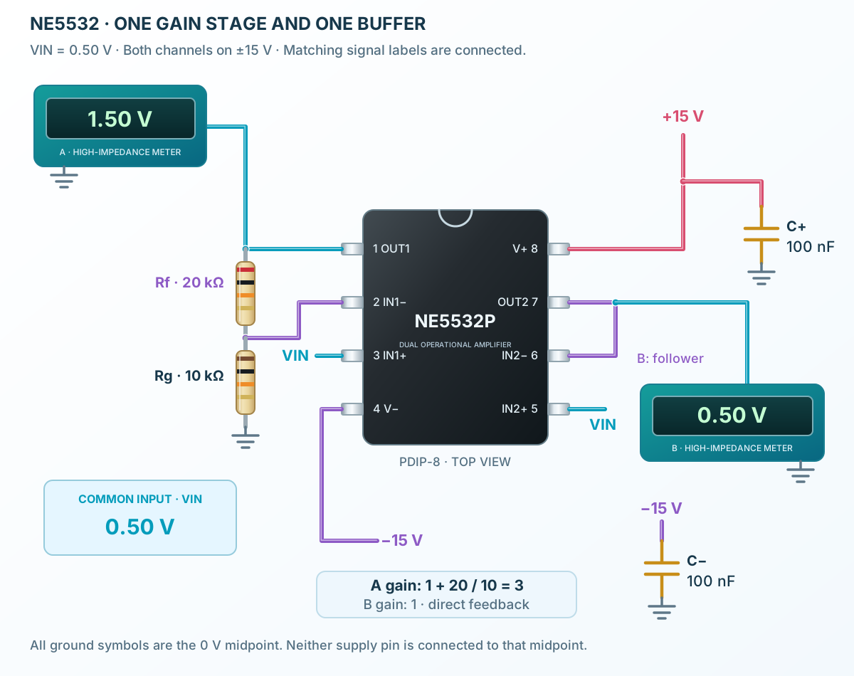
Follow the component values and pin connections
Use +15 V at pin 8 and −15 V at pin 4, with a 100 nF bypass from each rail to signal ground.
Add the 20 kΩ / 10 kΩ network to channel A and join pins 7 and 6 for channel B.
At a nominal input of 0.50 V, expect about 1.50 V from A and 0.50 V from B under light DC loading.
Two low-noise bipolar input stages and compensated output paths.
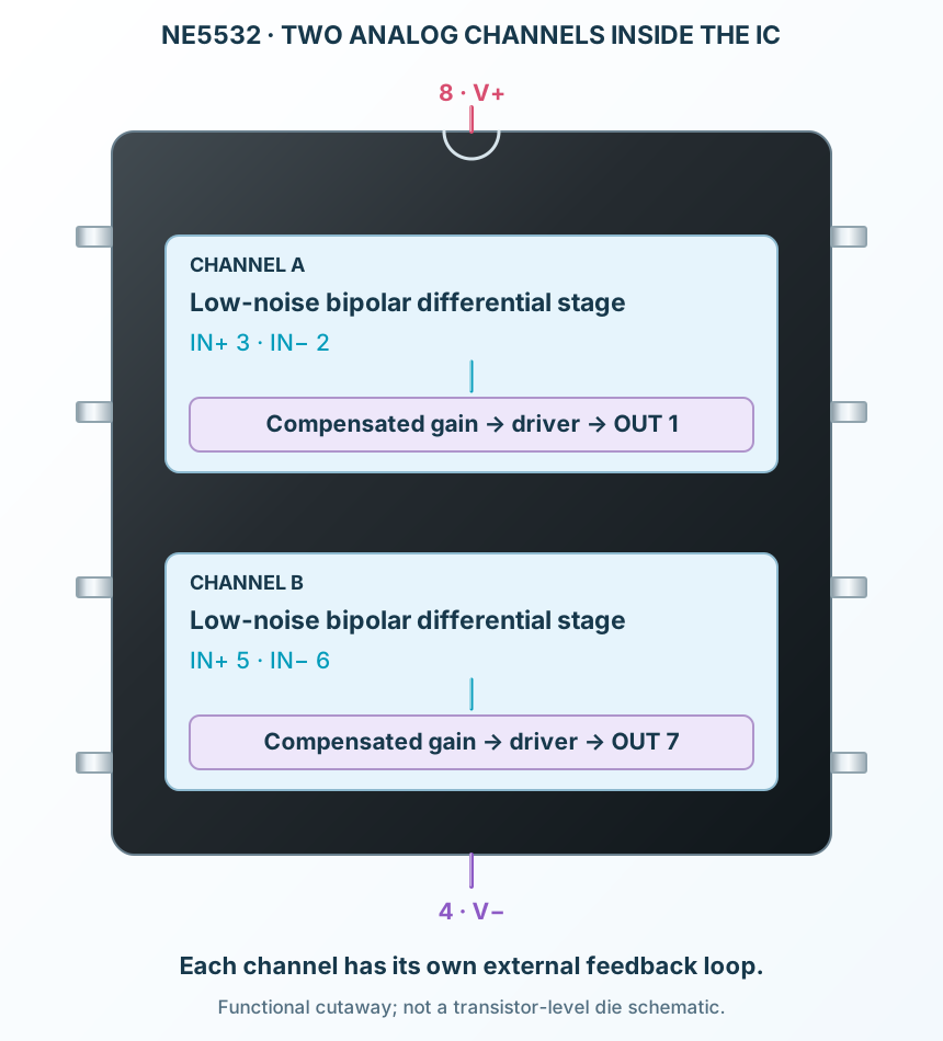
Select a stage to see its role and connections
The bipolar differential inputs offer low voltage noise, but draw bias current. The resulting error depends on source resistance and the feedback network.
Each channel has an internal voltage-gain path and frequency compensation.
Separate output drivers serve the two channels. Output swing depends on load and rail headroom; short-circuit protection is not a continuous-load rating.
Signal names, electrical functions and connection guidance
Scroll within the table to see all columns and rows.
| Pin | Signal | Type | Function & connection |
|---|---|---|---|
| OUT1 | Analog output | Channel A output.Connection guidanceReturn to IN1− through 20 kΩ; connect a high-impedance meter. | |
| IN1− | Inverting input | Channel A negative-feedback node.Connection guidanceJoin 20 kΩ from OUT1 and 10 kΩ to signal ground. | |
| IN1+ | Non-inverting input | Channel A signal input.Connection guidanceApply VIN = 0.50 V relative to the 0 V midpoint. | |
| V− | Negative supply | Negative rail shared by both amplifiers.Connection guidanceConnect −15 V; bypass locally to 0 V with 100 nF. | |
| IN2+ | Non-inverting input | Channel B signal input.Connection guidanceConnect to the same VIN in the illustrated follower. | |
| IN2− | Inverting input | Channel B feedback input.Connection guidanceConnect directly to OUT2 pin 7. | |
| OUT2 | Analog output | Channel B output.Connection guidanceConnect to IN2−; leave unloaded or use a high-impedance instrument. | |
| V+ | Positive supply | Positive rail shared by both amplifiers.Connection guidanceConnect +15 V; bypass locally to 0 V with 100 nF. |
No pins match these filters. Try another signal name or reset the filters.
TI NE5532 commercial grade
Scroll within the table to see all columns and rows.
| Parameter | Value | Conditions / notes |
|---|---|---|
| Positive supply | +5 to +15 V | Relative to signal midpoint |
| Negative supply | −5 to −15 V | Relative to signal midpoint |
| Ambient temperature | 0 to +70°C | NE5532 / NE5532A |
| Example rails | ±15 V | Local bypass on each rail |
| SA grade | −40 to +85°C | Separate ordering family; not the illustrated NE part |
No specifications match. Try a parameter name or a unit.
The ±18 V absolute maximum is a stress limit, not the recommended operating supply.
±15 V · 25°C unless stated
Scroll within the table to see all columns and rows.
| Parameter | Value | Conditions / notes |
|---|---|---|
| Input offset voltage | 0.5 mV typical; 4 mV maximum | 5 mV maximum over temperature |
| Input bias current | 200 nA typical; 800 nA maximum | 1 µA maximum over temperature |
| Input offset current | 10 nA typical; 150 nA maximum | 200 nA maximum over temperature |
| Common-mode range | ±12 V minimum; ±13 V typical | ±15 V supply |
| Total supply current | 6 mA typical; 16 mA maximum | Both channels; no output load |
| Open-loop gain | 100 V/mV typical; 25 minimum | RL ≥ 2 kΩ; VO = ±10 V |
No specifications match. Try a parameter name or a unit.
Use resistor values that balance loading, noise and bias-current error.
±15 V · 25°C
Scroll within the table to see all columns and rows.
| Parameter | Value | Conditions / notes |
|---|---|---|
| Unity-gain bandwidth | 12 MHz typical | Manufacturer B1 characteristic |
| Slew rate | 5 V/µs typical | Unity gain |
| Voltage noise at 1 kHz | 5 nV/√Hz typical | NE5532 |
| Voltage noise at 30 Hz | 8 nV/√Hz typical | NE5532 |
| Current noise at 1 kHz | 0.7 pA/√Hz typical | Source resistance converts this to voltage noise |
| Current noise at 30 Hz | 2.7 pA/√Hz typical | Low-frequency input-current noise |
No specifications match. Try a parameter name or a unit.
Noise densities are not total RMS noise; integrate over the circuit’s effective bandwidth.
Feedback, signal and loading
Scroll within the table to see all columns and rows.
| Parameter | Value | Conditions / notes |
|---|---|---|
| Large differential input | Limit input current | Internal protection diodes conduct around a 0.6 V difference |
| Unused channel | Give it defined feedback | The example uses channel B as an unloaded follower |
| Supply bypass | 100 nF per rail, close to IC | Add board-level bulk capacitance as required |
| Capacitive loads | Check stability | Do not assume an arbitrary cable can be driven directly |
| Short-circuit current | 38 mA typical test characteristic | Not a recommended continuous operating current |
No specifications match. Try a parameter name or a unit.
Keep signal returns away from high-current paths and check the actual output load.
±15 V rails · 0 V signal reference
Scroll within the table to see all columns and rows.
| Parameter | Value | Conditions / notes |
|---|---|---|
| Input VIN | 0.50 V | Pins 3 and 5; common signal ground |
| Channel A feedback | 20 kΩ | OUT1 pin 1 to IN1− pin 2 |
| Channel A ground resistor | 10 kΩ | IN1− pin 2 to 0 V |
| Channel A ideal output | 1.50 V | 0.50 × (1 + 20 / 10) |
| Channel B feedback | Direct connection | OUT2 pin 7 to IN2− pin 6 |
| Channel B ideal output | 0.50 V | Unity-gain follower |
| Bypass capacitors | 100 nF per rail | Each supply rail to the 0 V midpoint |
No specifications match. Try a parameter name or a unit.
The 0 V reference is not the negative supply pin. Keep both rail-bypass loops short.
NE5532P · PDIP-8
Scroll within the table to see all columns and rows.
| Parameter | Value | Conditions / notes |
|---|---|---|
| Lead pitch | 2.54 mm | Through-hole |
| Channel A | OUT1 1; IN1− 2; IN1+ 3 | Independent feedback loop |
| Channel B | IN2+ 5; IN2− 6; OUT2 7 | Independent feedback loop |
| Supply | V− 4; V+ 8 | Shared by both channels |
| Package orientation | Top view; pin 1 at the marker | Counterclockwise numbering |
No specifications match. Try a parameter name or a unit.
This dual-amplifier pinout differs from single amplifiers such as TL081 or LM741.
No matching rowsTry a pin name, parameter, unit or test condition, or reset the filters.
Apply controlled gain to suitable line-level signals, with enough supply headroom for the peaks.
Manufacturer application guideUse each channel for a separate feedback network; account for resistor noise and source impedance.
Manufacturer application guideBuffer a compatible analog stage while checking the load, cable capacitance and required output swing.
Manufacturer application guideFind NE5532 in the Components Library to place its schematic symbol and connect its pins.
Reference page · circuit simulation model not yet availableOpen ProTech