P6KE12AUnidirectional transient suppressor
Read the stand-off voltage before choosing a protector.
Manufacturer-referenced
Vishay General Semiconductor · P6KE12A-E3
DO-1588369 · Revision 27 September 2021P6KE12A is an axial unidirectional transient-voltage suppressor. Its name refers to a nominal breakdown level, not a continuously safe 12 V input rail. The band marks the cathode, which connects to the positive protected node. This page follows Vishay’s DO-15 part and also presents SMBJ12A as a separately specified SMD alternative. Their stand-off and clamping voltages differ, so the package switch changes the reference device as well as its footprint. Neither is automatically interchangeable in an existing protection design. The explanatory circuit uses a nominal 9 V input, a coordinated fuse and a TVS across the protected rail. The axial part has a 10.2 V stand-off rating, leaving some nominal margin; real supply tolerance and transients still require review. Keep the return short and ensure the load can withstand the actual clamped voltage.
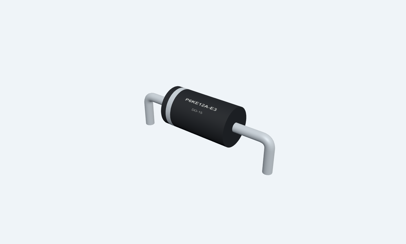
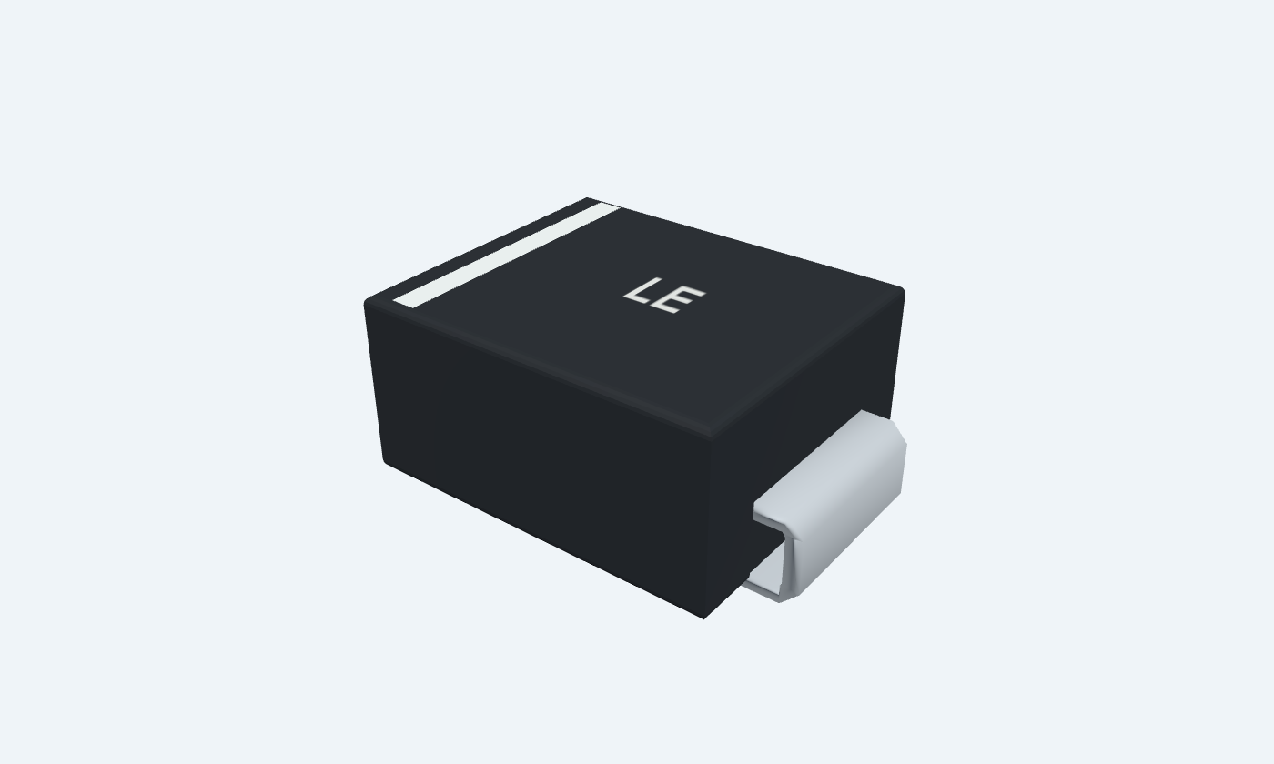

2Physical pins
P6KE12A-E3DO-15
Manufacturer-referencedVishay General Semiconductor
Pin diagram
Select a pin to explore its connection
Highlight
P6KE12ADO-15Top view · band at K1 · A2 opposite
P6KE12ASMBTop view · cathode 1 at band · anode 2 opposite
Click a lead or use the arrow keys. Top view · band at K1 · A2 opposite
PIN 1 · Protected positive rail
CathodeK
Function
Banded terminal connected to the protected positive rail.
How to connect
Place close to the input after the coordinated fuse.
Electrical note
Axial stand-off is 10.2 V; SMBJ12A uses 12 V. Neither number is its surge clamping voltage.
PIN 2 · Ground return
AnodeA
Function
Return for reverse avalanche current.
How to connect
Use a short path to the common ground.
Electrical note
Reverse supply polarity forward-biases this unidirectional device.
Key specifications
Stand-off, breakdown and clamping voltage must be checked separately.
Axial stand-off10.2 V
Axial breakdown11.4–12.6 V · at 1 mA
Axial maximum clamp16.7 V · at 35.9 A pulse
Peak pulse power600 W · specified pulse
Package details
P6KE12A-E3 · DO-15
| Property | Details |
|---|---|
| Manufacturer | Vishay General Semiconductor |
| Part number | P6KE12A-E3 |
| Package | DO-15 |
| Connections | 2 pins |
| Mounting | Through-hole |
| Lead pitch | 12.7 mm · formed lead pitch |
| Package code | DO-204AC |
| Thermal reference | 175°C junction maximum; pulse and lead cooling conditions apply |
Selected TVS device
Two separately specified references
Manufacturer specifications 3 parameters
Scroll sideways to see all columns.
| Parameter | Value | Conditions / notes |
|---|---|---|
| Axial | P6KE12A-E3 | DO-15; band = cathode |
| SMD alternative | SMBJ12A-E3 | SMB; LE marking |
| Pad convention | K1 / A2 | Positive node / return |
No specifications match. Try a parameter name or a unit.
SMD is an alternative, not the same silicon in a different body.
Axial voltage thresholds
Vishay P6KE12A at 25°C
Manufacturer specifications 5 parameters
Scroll sideways to see all columns.
| Parameter | Value | Conditions / notes |
|---|---|---|
| Stand-off | 10.2 V | Reverse working voltage |
| Breakdown | 11.4–12.6 V | 1 mA; pulse ≤50 ms |
| Leakage | 5 µA maximum | At stand-off |
| Clamping | 16.7 V maximum | 35.9 A pulse |
| Temperature coefficient | 0.078%/°C maximum | Breakdown voltage |
No specifications match. Try a parameter name or a unit.
A nominal 12 V supply exceeds this stand-off voltage.
Axial pulse and temperature limits
Waveform and cooling dependent
Manufacturer specifications 4 parameters
Scroll sideways to see all columns.
| Parameter | Value | Conditions / notes |
|---|---|---|
| Peak pulse power | 600 W | 10/1000 µs; derate above 25°C |
| Junction / storage | −55 to +175°C | Absolute limits |
| Forward surge | 100 A | 8.3 ms half sine; max 4 pulses/minute |
| Power dissipation | 5 W | Infinite heatsink; lead temperature 75°C |
No specifications match. Try a parameter name or a unit.
Continuous and pulse limits are different.
SMBJ12A alternative
Vishay 88392 selected row
Manufacturer specifications 7 parameters
Scroll sideways to see all columns.
| Parameter | Value | Conditions / notes |
|---|---|---|
| Stand-off | 12 V | Different from axial 10.2 V |
| Breakdown | 13.3–14.7 V | 1 mA |
| Leakage | 5 µA maximum | At stand-off |
| Maximum clamp | 19.9 V | 30.2 A pulse |
| Pulse power | 600 W | 10/1000 µs; mounting and derating apply |
| Junction / storage | −55 to +150°C | Different from axial limit |
| Package / marking | SMB / LE | Separate PDF in SMD view |
No specifications match. Try a parameter name or a unit.
Confirm that the protected circuit tolerates the higher clamp.
Package and mounting
Two distinct footprints
Manufacturer specifications 5 parameters
Scroll sideways to see all columns.
| Parameter | Value | Conditions / notes |
|---|---|---|
| Axial body | 6.15–6.55 × Ø3.3–3.5 mm | DO-15 |
| Axial lead diameter | 0.71–0.86 mm | Round silver-plated leads |
| Formed pitch / hole | 12.7 / 1.1 mm | 2 mm copper pads |
| SMD lands | 1.7155 × 2.18 mm | 3.8745 mm centers |
| SMD inner gap | 2.159 mm | Cathode left |
No specifications match. Try a parameter name or a unit.
Verify assembly tolerance and thermal paths.
9 V input protection
Conceptual design checks
Manufacturer specifications 5 parameters
Scroll sideways to see all columns.
| Parameter | Value | Conditions / notes |
|---|---|---|
| Axial nominal headroom | 1.2 V | 10.2 V stand-off minus 9 V input |
| Axial clamp point | 16.7 V at 35.9 A | About 600 W pulse arithmetic |
| SMD clamp point | 19.9 V at 30.2 A | Different load-voltage requirement |
| Fuse and source impedance | Coordinate from actual source | Do not assume unlimited surge energy |
| Ground return | Short and wide | Reduce inductive overshoot |
No specifications match. Try a parameter name or a unit.
Values explain the datasheet; this is not a qualified surge-protection design.
Connections by function
Select a pin for its function, connection guidance and electrical notes.
Protected positive rail1 pin
Ground return1 pin
Protected positive rail1 pin
Ground return1 pin
P6KE12A at a glance
Follow the labeled connections and functional stages
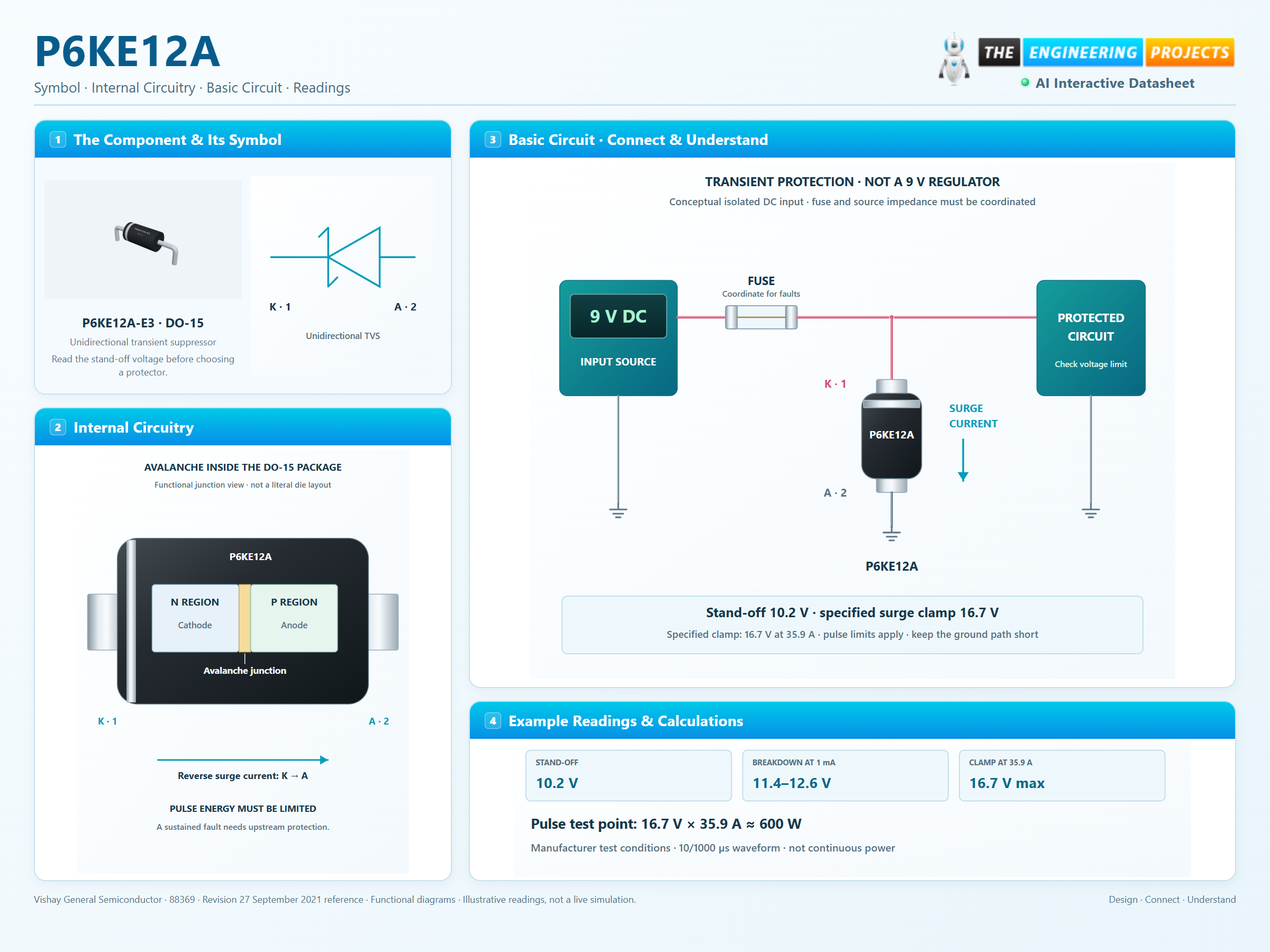
How it works
3 stages · Explore one step at a time
Normal input
At the working voltage the TVS is reverse biased; leakage remains.
Transient arrives
As the junction enters breakdown, reverse current rises and limits the rail excursion.
Energy and fault protection
The surge must stay within the pulse envelope. A coordinated fuse or other upstream protection handles sustained faults.
Step 1 of 3
P6KE12A in a circuit
TVS across the input, with coordinated upstream protection.
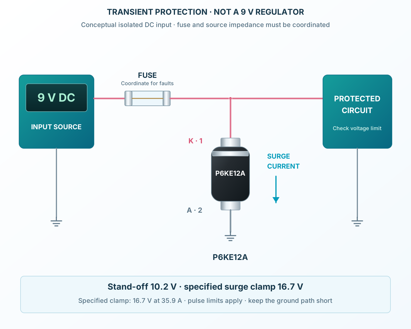
Connect it, step by step
Follow the component values and pin connections
Protected node
Connect the banded cathode to the protected positive rail.
Short return
Connect the anode directly to the local return.
Coordinate protection
The TVS does not replace a fuse for sustained faults.
Inside P6KE12A
Avalanche action inside the axial package.
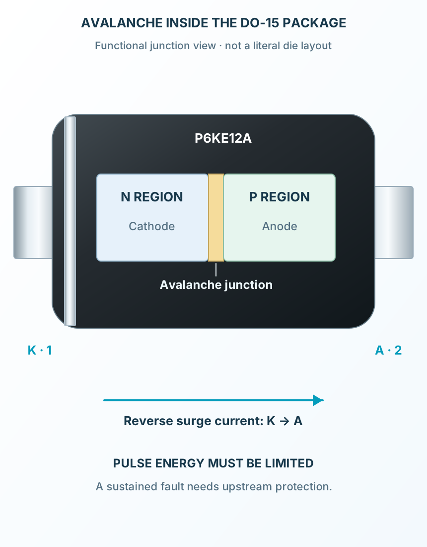
Explore the circuit
Select a stage to see its role and connections
Normal input
At the working voltage the TVS is reverse biased; leakage remains.
Transient arrives
As the junction enters breakdown, reverse current rises and limits the rail excursion.
Energy and fault protection
The surge must stay within the pulse envelope. A coordinated fuse or other upstream protection handles sustained faults.
Selected packageDO-15P6KE12A-E3
Physical connections2 pinsPackage-specific numbering
Reference collection7 tables29 parameters & pin functions
Pin reference
Signal names, electrical functions and connection guidance
Physical pin numbers2 pins
Scroll within the table to see all columns and rows.
| Pin | Signal | Type | Function & connection |
|---|---|---|---|
| K | Cathode | Banded terminal connected to the protected positive rail.Connection guidancePlace close to the input after the coordinated fuse. Axial stand-off is 10.2 V; SMBJ12A uses 12 V. Neither number is its surge clamping voltage. | |
| A | Anode | Return for reverse avalanche current.Connection guidanceUse a short path to the common ground. Reverse supply polarity forward-biases this unidirectional device. |
No pins match these filters. Try another signal name or reset the filters.
Selected TVS device
Two separately specified references
Manufacturer-referenced values3 parameters
Scroll within the table to see all columns and rows.
| Parameter | Value | Conditions / notes |
|---|---|---|
| Axial | P6KE12A-E3 | DO-15; band = cathode |
| SMD alternative | SMBJ12A-E3 | SMB; LE marking |
| Pad convention | K1 / A2 | Positive node / return |
No specifications match. Try a parameter name or a unit.
SMD is an alternative, not the same silicon in a different body.
Axial voltage thresholds
Vishay P6KE12A at 25°C
Manufacturer-referenced values5 parameters
Scroll within the table to see all columns and rows.
| Parameter | Value | Conditions / notes |
|---|---|---|
| Stand-off | 10.2 V | Reverse working voltage |
| Breakdown | 11.4–12.6 V | 1 mA; pulse ≤50 ms |
| Leakage | 5 µA maximum | At stand-off |
| Clamping | 16.7 V maximum | 35.9 A pulse |
| Temperature coefficient | 0.078%/°C maximum | Breakdown voltage |
No specifications match. Try a parameter name or a unit.
A nominal 12 V supply exceeds this stand-off voltage.
Axial pulse and temperature limits
Waveform and cooling dependent
Manufacturer-referenced values4 parameters
Scroll within the table to see all columns and rows.
| Parameter | Value | Conditions / notes |
|---|---|---|
| Peak pulse power | 600 W | 10/1000 µs; derate above 25°C |
| Junction / storage | −55 to +175°C | Absolute limits |
| Forward surge | 100 A | 8.3 ms half sine; max 4 pulses/minute |
| Power dissipation | 5 W | Infinite heatsink; lead temperature 75°C |
No specifications match. Try a parameter name or a unit.
Continuous and pulse limits are different.
SMBJ12A alternative
Vishay 88392 selected row
Manufacturer-referenced values7 parameters
Scroll within the table to see all columns and rows.
| Parameter | Value | Conditions / notes |
|---|---|---|
| Stand-off | 12 V | Different from axial 10.2 V |
| Breakdown | 13.3–14.7 V | 1 mA |
| Leakage | 5 µA maximum | At stand-off |
| Maximum clamp | 19.9 V | 30.2 A pulse |
| Pulse power | 600 W | 10/1000 µs; mounting and derating apply |
| Junction / storage | −55 to +150°C | Different from axial limit |
| Package / marking | SMB / LE | Separate PDF in SMD view |
No specifications match. Try a parameter name or a unit.
Confirm that the protected circuit tolerates the higher clamp.
Package and mounting
Two distinct footprints
Manufacturer-referenced values5 parameters
Scroll within the table to see all columns and rows.
| Parameter | Value | Conditions / notes |
|---|---|---|
| Axial body | 6.15–6.55 × Ø3.3–3.5 mm | DO-15 |
| Axial lead diameter | 0.71–0.86 mm | Round silver-plated leads |
| Formed pitch / hole | 12.7 / 1.1 mm | 2 mm copper pads |
| SMD lands | 1.7155 × 2.18 mm | 3.8745 mm centers |
| SMD inner gap | 2.159 mm | Cathode left |
No specifications match. Try a parameter name or a unit.
Verify assembly tolerance and thermal paths.
9 V input protection
Conceptual design checks
Manufacturer-referenced values5 parameters
Scroll within the table to see all columns and rows.
| Parameter | Value | Conditions / notes |
|---|---|---|
| Axial nominal headroom | 1.2 V | 10.2 V stand-off minus 9 V input |
| Axial clamp point | 16.7 V at 35.9 A | About 600 W pulse arithmetic |
| SMD clamp point | 19.9 V at 30.2 A | Different load-voltage requirement |
| Fuse and source impedance | Coordinate from actual source | Do not assume unlimited surge energy |
| Ground return | Short and wide | Reduce inductive overshoot |
No specifications match. Try a parameter name or a unit.
Values explain the datasheet; this is not a qualified surge-protection design.
No matching rowsTry a pin name, parameter, unit or test condition, or reset the filters.
DC input protection
Protect appropriately rated downstream circuitry from limited transients.
Manufacturer application guideInductive transients
Choose a clamp from the actual pulse current, voltage and repetition rate.
Manufacturer application guidePeripheral interfaces
Check signal voltage, capacitance and surge requirements before selecting a TVS.
Manufacturer application guideTake it into ProTech
Find P6KE12A in the Components Library to place its schematic symbol and connect its pins.
Reference page · circuit simulation model not yet availableOpen ProTech