Real View
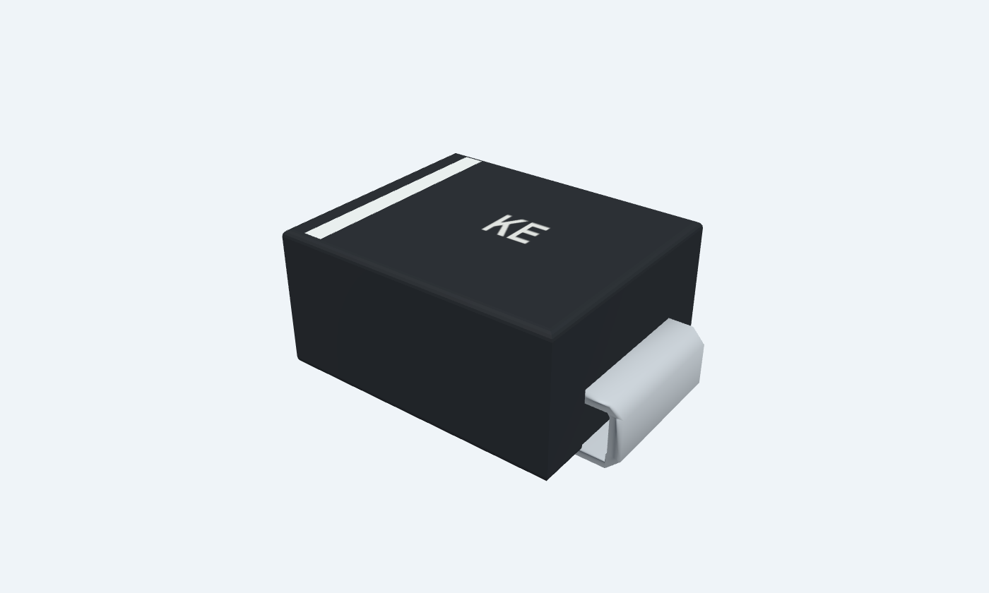
Give a voltage spike a short path to ground.
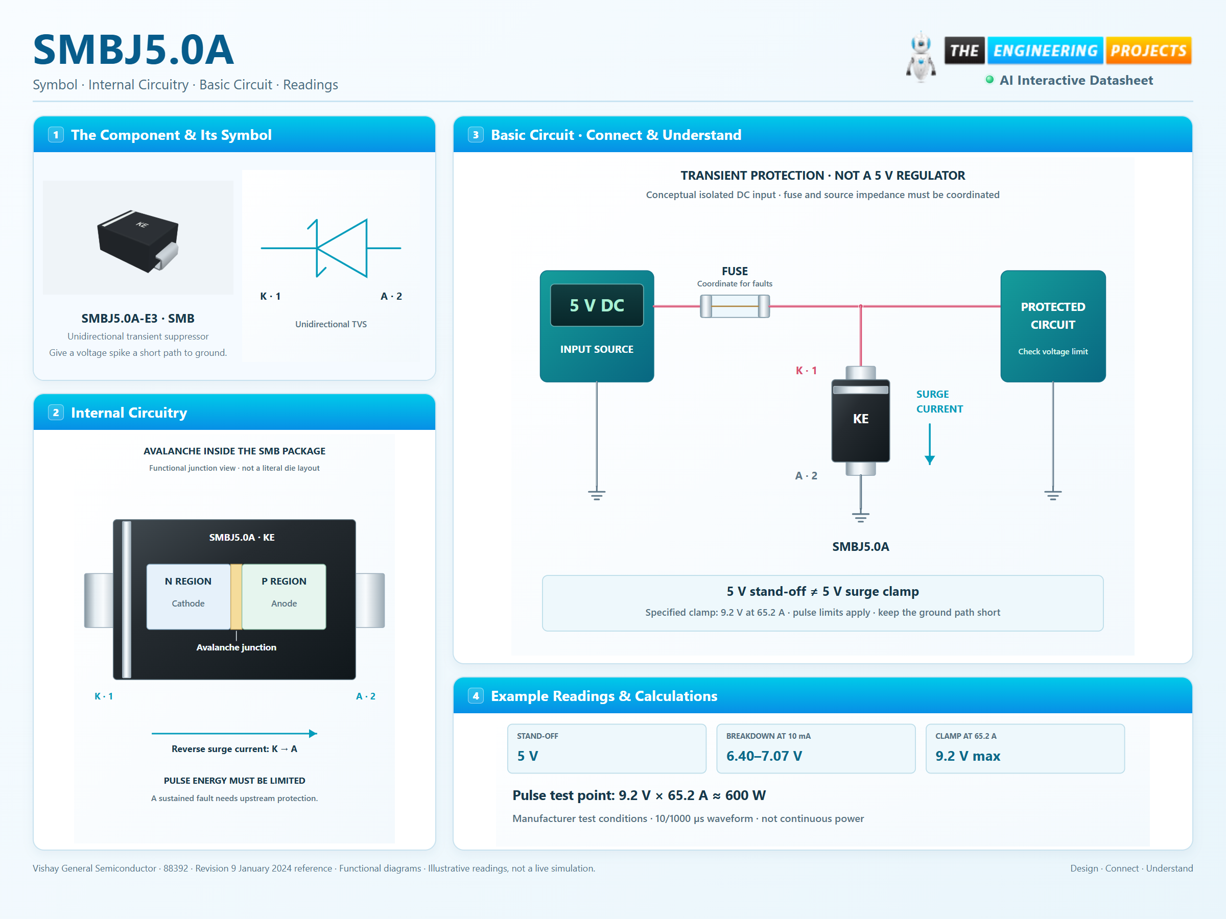
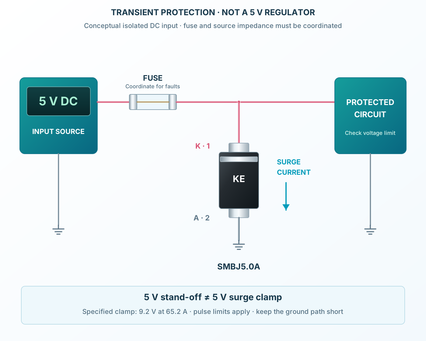
SMBJ5.0A is a unidirectional transient-voltage suppressor. It connects across a protected DC rail, with its banded cathode at the positive node and its anode at ground. A short, low-inductance return helps divert surge current away from the load. The stand-off voltage, breakdown voltage and clamping voltage describe different conditions. A 5 V stand-off rating does not mean the rail will be held at exactly 5 V during a surge. The protected circuit must tolerate the actual clamp voltage, including wiring overshoot. This reference follows Vishay’s commercial SMB part. The diagram illustrates a protected 5 V input with a fuse and upstream source impedance. The fuse handles sustained faults; the TVS handles appropriately limited transients. Select both from the real source, load and pulse requirements.
Select a pin to explore its connection
Click a lead or use the arrow keys. Top view · cathode 1 at band · anode 2 opposite
Banded terminal connected to the protected positive rail.
Place close to the input after the coordinated fuse.
5 V stand-off is not the surge clamping voltage.
Return for reverse avalanche current.
Use a short path to the common ground.
Reverse supply polarity forward-biases this unidirectional device.
Stand-off, breakdown and clamping voltage must be checked separately.
SMBJ5.0A-E3 · SMB
| Property | Details |
|---|---|
| Manufacturer | Vishay General Semiconductor |
| Part number | SMBJ5.0A-E3 |
| Package | SMB |
| Connections | 2 pins |
| Mounting | Surface mount |
| Lead pitch | 3.8745 mm · land centers |
| Package code | DO-214AA |
| Thermal reference | Pulse capability depends on waveform, temperature and mounting |
Vishay SMBJ5.0A-E3
Scroll sideways to see all columns.
| Parameter | Value | Conditions / notes |
|---|---|---|
| Configuration | Unidirectional | SMBJ5.0CA is a different device |
| Package / marking | SMB / KE | DO-214AA; band = cathode |
| Pad convention | K1 / A2 | Positive rail / return |
No specifications match. Try a parameter name or a unit.
This page does not substitute bidirectional specifications.
25°C selected device row
Scroll sideways to see all columns.
| Parameter | Value | Conditions / notes |
|---|---|---|
| Stand-off voltage | 5 V | Reverse working voltage |
| Breakdown range | 6.40–7.07 V | 10 mA; pulse ≤50 ms |
| Maximum leakage | 800 µA | At stand-off |
| Maximum clamp | 9.2 V | 65.2 A specified pulse |
| Breakdown temperature coefficient | 0.057%/°C maximum | Manufacturer parameter |
No specifications match. Try a parameter name or a unit.
Clamping voltage is higher than both stand-off and breakdown.
Waveform and mounting dependent
Scroll sideways to see all columns.
| Parameter | Value | Conditions / notes |
|---|---|---|
| Peak pulse power | 600 W | 10/1000 µs; derate above 25°C |
| Peak pulse current | 65.2 A | Specified waveform; not continuous |
| Junction / storage | −55 to +150°C | Absolute limits |
| Forward surge | 100 A | Single 8.3 ms half sine |
| Power dissipation | 5 W | Infinite heatsink at 50°C; not a small-board guarantee |
No specifications match. Try a parameter name or a unit.
The pulse test uses specified copper mounting.
Manufacturer outline and authored lands
Scroll sideways to see all columns.
| Parameter | Value | Conditions / notes |
|---|---|---|
| Body | 4.06–4.57 × 3.30–3.94 mm | Molded outline |
| Height | 2.13–2.44 mm | Package drawing |
| Overall span | 5.21–5.59 mm | Including contacts |
| Authored copper | 1.7155 × 2.18 mm | 3.8745 mm centers |
| Inner gap | 2.159 mm | Verify assembly tolerances |
No specifications match. Try a parameter name or a unit.
Keep the surge loop short.
Conceptual 5 V input
Scroll sideways to see all columns.
| Parameter | Value | Conditions / notes |
|---|---|---|
| Fuse | Coordinate with fault current | No universal fuse rating is implied |
| Source impedance | Must limit available surge energy | Include cables and upstream protection |
| Load tolerance | Must exceed actual transient voltage | 9.2 V specified clamp plus overshoot |
| TVS return | Short and wide | Minimize parasitic inductance |
| Pulse power arithmetic | 9.2 × 65.2 ≈ 600 W | Specified test point, not continuous power |
No specifications match. Try a parameter name or a unit.
This circuit is explanatory, not a validated protection design.
Select a pin for its function, connection guidance and electrical notes.
Follow the labeled connections and functional stages
3 stages · Explore one step at a time
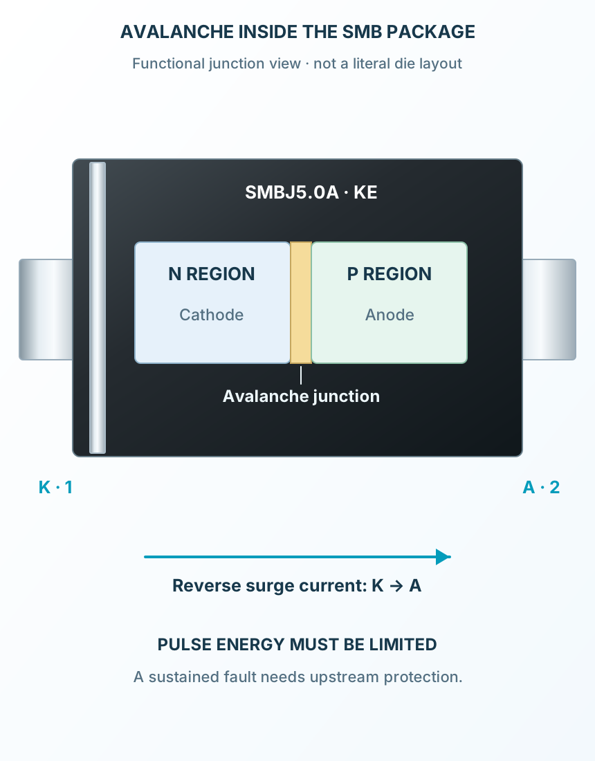
At the working voltage the TVS is reverse biased; leakage remains.
As the junction enters breakdown, reverse current rises and limits the rail excursion.
The surge must stay within the pulse envelope. A coordinated fuse or other upstream protection handles sustained faults.
TVS across the input, with coordinated upstream protection.
Follow the component values and pin connections
Connect the banded cathode to the protected positive rail.
Connect the anode directly to the local return.
The TVS does not replace a fuse for sustained faults.
Compact conceptual junction cutaway.
Select a stage to see its role and connections
At the working voltage the TVS is reverse biased; leakage remains.
As the junction enters breakdown, reverse current rises and limits the rail excursion.
The surge must stay within the pulse envelope. A coordinated fuse or other upstream protection handles sustained faults.
Signal names, electrical functions and connection guidance
Scroll within the table to see all columns and rows.
| Pin | Signal | Type | Function & connection |
|---|---|---|---|
| K | Cathode | Banded terminal connected to the protected positive rail.Connection guidancePlace close to the input after the coordinated fuse. 5 V stand-off is not the surge clamping voltage. | |
| A | Anode | Return for reverse avalanche current.Connection guidanceUse a short path to the common ground. Reverse supply polarity forward-biases this unidirectional device. |
No pins match these filters. Try another signal name or reset the filters.
Vishay SMBJ5.0A-E3
Scroll within the table to see all columns and rows.
| Parameter | Value | Conditions / notes |
|---|---|---|
| Configuration | Unidirectional | SMBJ5.0CA is a different device |
| Package / marking | SMB / KE | DO-214AA; band = cathode |
| Pad convention | K1 / A2 | Positive rail / return |
No specifications match. Try a parameter name or a unit.
This page does not substitute bidirectional specifications.
25°C selected device row
Scroll within the table to see all columns and rows.
| Parameter | Value | Conditions / notes |
|---|---|---|
| Stand-off voltage | 5 V | Reverse working voltage |
| Breakdown range | 6.40–7.07 V | 10 mA; pulse ≤50 ms |
| Maximum leakage | 800 µA | At stand-off |
| Maximum clamp | 9.2 V | 65.2 A specified pulse |
| Breakdown temperature coefficient | 0.057%/°C maximum | Manufacturer parameter |
No specifications match. Try a parameter name or a unit.
Clamping voltage is higher than both stand-off and breakdown.
Waveform and mounting dependent
Scroll within the table to see all columns and rows.
| Parameter | Value | Conditions / notes |
|---|---|---|
| Peak pulse power | 600 W | 10/1000 µs; derate above 25°C |
| Peak pulse current | 65.2 A | Specified waveform; not continuous |
| Junction / storage | −55 to +150°C | Absolute limits |
| Forward surge | 100 A | Single 8.3 ms half sine |
| Power dissipation | 5 W | Infinite heatsink at 50°C; not a small-board guarantee |
No specifications match. Try a parameter name or a unit.
The pulse test uses specified copper mounting.
Manufacturer outline and authored lands
Scroll within the table to see all columns and rows.
| Parameter | Value | Conditions / notes |
|---|---|---|
| Body | 4.06–4.57 × 3.30–3.94 mm | Molded outline |
| Height | 2.13–2.44 mm | Package drawing |
| Overall span | 5.21–5.59 mm | Including contacts |
| Authored copper | 1.7155 × 2.18 mm | 3.8745 mm centers |
| Inner gap | 2.159 mm | Verify assembly tolerances |
No specifications match. Try a parameter name or a unit.
Keep the surge loop short.
Conceptual 5 V input
Scroll within the table to see all columns and rows.
| Parameter | Value | Conditions / notes |
|---|---|---|
| Fuse | Coordinate with fault current | No universal fuse rating is implied |
| Source impedance | Must limit available surge energy | Include cables and upstream protection |
| Load tolerance | Must exceed actual transient voltage | 9.2 V specified clamp plus overshoot |
| TVS return | Short and wide | Minimize parasitic inductance |
| Pulse power arithmetic | 9.2 × 65.2 ≈ 600 W | Specified test point, not continuous power |
No specifications match. Try a parameter name or a unit.
This circuit is explanatory, not a validated protection design.
No matching rowsTry a pin name, parameter, unit or test condition, or reset the filters.
Protect appropriately rated downstream circuitry from limited transients.
Manufacturer application guideChoose a clamp from the actual pulse current, voltage and repetition rate.
Manufacturer application guideCheck signal voltage, capacitance and surge requirements before selecting a TVS.
Manufacturer application guideFind SMBJ5.0A in the Components Library to place its schematic symbol and connect its pins.
Reference page · circuit simulation model not yet availableOpen ProTech