Real View
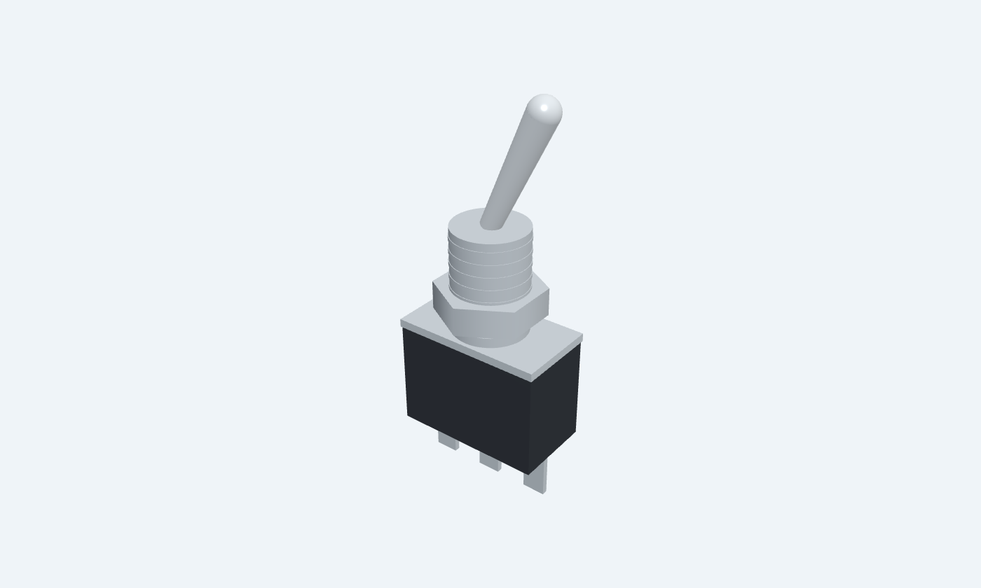
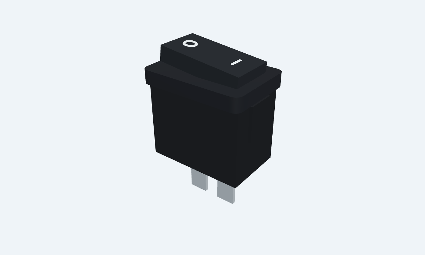
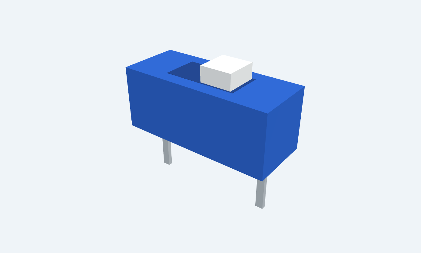
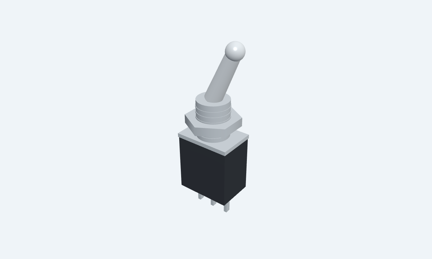
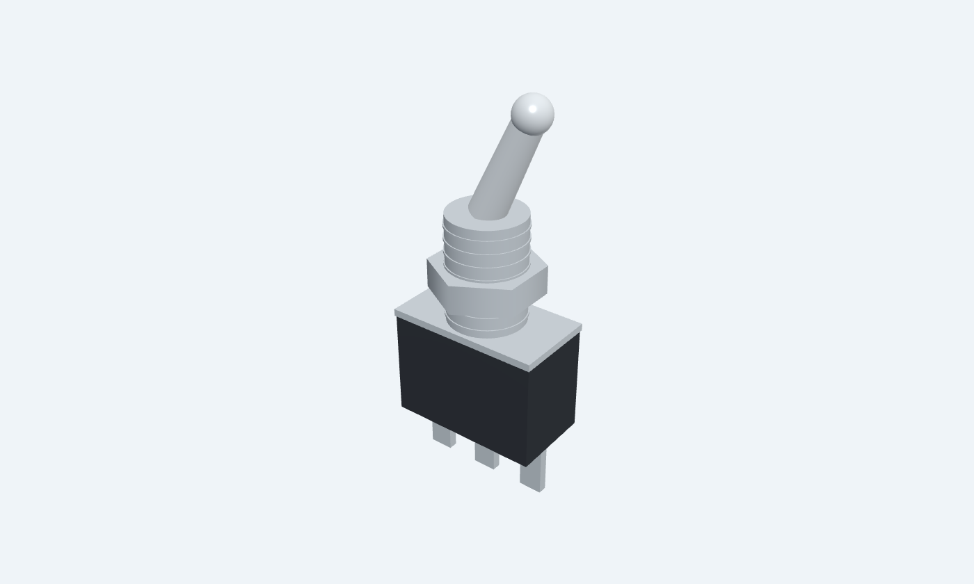
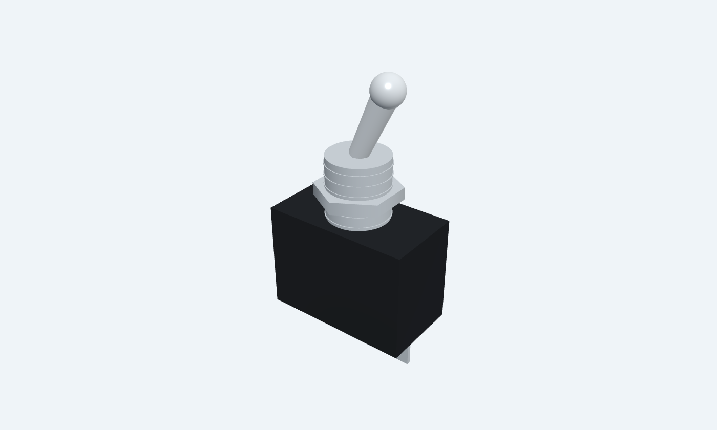
Flip it and it stays.
C&K (Littelfuse) · 7101SYZQE
Miniature toggle7000 Series Miniature Toggle Switches, revised 10/02/26A toggle, rocker or DIP switch latches: it stays in the position it was put in until it is moved again. Used as an on-off switch it connects or disconnects two terminals, so a circuit can be powered, enabled or configured without a program holding it. The six switches here run from 50 mA to 20 A. The CTS 206 DIP switch carries only 50 mA at 24 V DC switching: a DIP switch sets configuration bits, never power. The KCD11 rocker carries 1 A at 250 V AC, the E-Switch 200 and 100 toggles 3 A at 120 V AC or 28 V DC and 5 A at 120 V AC or 28 V DC, the C&K 7101 toggle 5 A at 120 V AC or 28 V DC, and the E-Switch ST4 20 A at 6–30 V DC. Contact resistance runs from 10 mΩ (the C&K and E-Switch 100 toggles) to 100 mΩ (rocker). The toggles and the rocker are panel parts: they mount in a front panel and are wired to the board, so their PCB footprint is a 2-pin header. The DIP switch solders straight into the board. The page, ProTech and the footprints number the terminals 1 and 2; the third terminal of the SPDT toggles is not used for on-off. ProTech’s LED toggle switch (small, medium, large) is the E-Switch 200, 100 and ST4; its lit tip is ProTech’s display of the position, the real bat is plain.
Select a pin to explore its connection
Click a lead or use the arrow keys. Lugs 2 (common) and 1 wired to header pads 2 and 1; lug 3 free
Toggle: end lug 1 (C&K) or terminal 3 (E-Switch). Rocker: one tab. DIP switch: pin 1, the square pad. Panel switches reach the board on header pad 1.
Connect to the supply or signal being switched.
A switch has no polarity; respect the voltage and current rating of the switch chosen.
Toggle: terminal 2, the centre (common) one. Rocker: the other tab. DIP switch: pin 2. Header pad 2.
Connect to the load, or to the input being configured.
Closed: 10 mΩ C&K toggle, 20 mΩ / 10 mΩ / 50 mΩ E-Switch 200 / 100 / ST4, 100 mΩ rocker, 50 mΩ DIP (maximum, initial).
Pick the switch by the load: a DIP switch sets logic levels (50 mA), a rocker or toggle switches power. Wire the switch in the positive feed so the load is dead when it is off, and stay inside the rating for the kind of load (lamps and motors draw several times their running current at switch-on).
7101SYZQE · Miniature toggle
| Property | Details |
|---|---|
| Manufacturer | C&K (Littelfuse) |
| Part number | 7101SYZQE |
| Package | Miniature toggle |
| Connections | 2 pins |
| Mounting | Panel mount · wired to a 2-pin header |
| Lead pitch | 2.54 mm pitch |
| Package code | switch-connector |
| Thermal reference | Contact heating at the rating: (5 A)² × 10 mΩ = 0.25 W |
Manufacturer scope and page conventions
Scroll sideways to see all columns.
| Parameter | Value | Conditions / notes |
|---|---|---|
| Reference parts | C&K (Littelfuse) 7101SYZQE · Shou Han KCD11-2P · CTS 206-1S · E-Switch 200MSP6T1B1M2QE · 100SP1T1B1M1QE · ST4SP2DT1C2 | One sheet each |
| Contact form | SPST on-off, latching | The C&K and E-Switch 200 / 100 toggles are SPDT: the common terminal 2 and one end terminal make the on-off switch |
| Terminal 1 | Toggle lug 1 (E-Switch: terminal 3) · rocker tab · DIP pin 1 (square) | ProTech pin 1 · footprint pad 1 |
| Terminal 2 | Toggle terminal 2 (common) · rocker tab · DIP pin 2 | ProTech pin 2 · footprint pad 2 |
| Panel switches | Toggles and rocker wired to a 2-pin header | Their own lugs are not PCB pins |
| Proteus symbol | SWITCH | 2 pins; ProTech’s Toggle Switch models it |
No specifications match. Try a parameter name or a unit.
A panel switch’s wires go to the header; the header is what the PCB carries.
From each manufacturer’s sheet · the numbers ProTech’s model and checks use
Scroll sideways to see all columns.
| Specification | C&K (Littelfuse) 7101SYZQE | Shou Han KCD11-2P | CTS 206-1S | E-Switch 200MSP6T1B1M2QE | E-Switch 100SP1T1B1M1QE | E-Switch ST4SP2DT1C2 |
|---|---|---|---|---|---|---|
| Contact rating (resistive) | 5 A at 120 V AC or 28 V DC; 2 A at 250 V AC (silver) | 1 A at 250 V AC (no DC rating in the sheet) | 50 mA at 24 V DC switching; 100 mA or 50 V DC carrying | 3 A at 120 V AC or 28 V DC; 1 A at 250 V AC (silver) | 5 A at 120 V AC or 28 V DC; 2 A at 250 V AC (silver) | 20 A at 6–30 V DC; 16(8) A at 125/250 V AC |
| Minimum load | gold contacts: 0.4 VA max at 20 V | not in datasheet | not in datasheet | gold contacts: 0.4 VA max at 20 V | gold contacts: 0.4 VA max at 20 V | not in datasheet |
| Contact resistance | 10 mΩ maximum (initial) | 100 mΩ maximum (initial) | 50 mΩ maximum (initial) | 20 mΩ maximum (initial) | 10 mΩ maximum (initial) | 50 mΩ maximum (initial) |
| Insulation resistance | ≥ 10⁹ Ω | ≥ 100 MΩ at 500 V DC | ≥ 1000 MΩ | ≥ 1000 MΩ | ≥ 1000 MΩ | ≥ 50 MΩ |
| Dielectric strength | 1000 V rms | 1500 V AC between terminals | 500 V AC for 1 min | 1000 V rms | 1000 V rms | 1500 V rms |
| Operation | lever, two positions 25° each side | rocker, two positions (O and —) | slide, two positions | lever, two positions 25° each side | lever, two positions 25° each side; torque max 5 kg·cm | 17 mm metal bat, two positions (OFF-ON) |
| Travel | lever 10.67 mm above the bushing | rocker 12 × 6.3 mm, about 3 mm proud | travel 2.03 mm | lever 9.40 mm above the bushing | lever 10.41 mm above the bushing | bat 17.00 mm above the bushing |
| Life | 100 000 electrical cycles at full load | 10 000 mechanical cycles | 10 000 cycles at 50 mA, 24 V DC | 30 000 mechanical, 6 000 at full load | 40 000 mechanical, 6 000 at full power | 10 000 electrical cycles |
| Contact bounce | not in the sheet | not in the sheet | not in the sheet | not in the sheet | not in the sheet | not in the sheet |
| Operating temperature | −30 to +85 °C | −25 to +85 °C | −55 to +85 °C | −40 to +85 °C | −40 to +85 °C | −10 to +55 °C |
| Size | case 12.70 × 6.86 mm, 1/4-40 bushing, hex nut | bezel 15 × 10.5 mm, panel cut-out 14 × 8.8 mm | 9.78 × 3.96 mm, 7.6 mm high | case 8.13 × 8.64 mm, 10-48 bushing 5.59 mm, nut 7.00 mm A/F | case 12.70 × 8.89 mm, 1/4-40 bushing 8.89 mm | case 28.80 × 21.00 mm, 15/32-32 bushing Ø12 mm, IP68 |
| Terminals | 4.70 mm (SPDT; pins 2 common and 1 used for ON-OFF) | 5.0 mm (2 pins, snap-in panel mount) | 7.62 mm row spacing (2 pins) | 2.54 mm (PC pins 1-2-3; pins 2 common and 3 used for OFF-ON) | 4.70 mm (solder lugs 1-2-3; pins 2 common and 3 used for ON-OFF) | 1/4 in quick-connect tabs (panel mount) |
| Look | chrome bat lever, nickel-plated hex nut and bushing, dark case | black bezel and rocker, O and bar marks | blue housing, white slider, ON arrow | side view: case, nickel bushing and nut, chrome bat lever; its tip lit red OFF, green ON (ProTech's display; the real bat is plain) | side view: case, nickel bushing and nut, chrome bat lever; its tip lit red OFF, green ON (ProTech's display; the real bat is plain) | side view: case, nickel bushing and nut, chrome bat lever; its tip lit red OFF, green ON (ProTech's display; the real bat is plain) |
No specifications match. Try a parameter name or a unit.
Contact resistance is the initial maximum; it rises with wear and contamination. Ratings are for resistive loads.
The same numbers drive the simulator, its checks and this page
Scroll sideways to see all columns.
| Parameter | Value | Conditions / notes |
|---|---|---|
| Closed | Rc of the switch chosen, between pins 1 and 2 | 10 mΩ toggle · 100 mΩ rocker · 50 mΩ DIP · 20 mΩ / 10 mΩ / 50 mΩ E-Switch 200 / 100 / ST4 |
| Open | No branch | Insulation resistance not modelled |
| Rating check | Warns above the switch’s current or voltage | 5 A / 28 V · 1 A / 250 V · 50 mA / 24 V · 3 A / 28 V · 5 A / 28 V · 20 A / 30 V |
| Position | Saved with the circuit | A click or Enter flips it while running |
| Size | Drawn at true size | Toggle 12.70 × 6.86 mm, rocker 15 × 10.5 mm, DIP 9.78 × 3.96 mm, E-Switch toggles 8.13, 12.70 and 28.80 mm wide |
| LED toggle switch | The E-Switch 200, 100 and ST4 (small, medium, large) | Its lit tip, red OFF and green ON, is ProTech’s display; the real bat is plain |
No specifications match. Try a parameter name or a unit.
Change the switch in Properties: the drawing, rating, contact resistance and PCB footprint follow it.
Toggle or rocker in the positive wire
Scroll sideways to see all columns.
| Parameter | Value | Conditions / notes |
|---|---|---|
| Toggle drop | 5 mV | 0.5 A × 10 mΩ |
| Toggle contact heating | 2.5 mW | (0.5 A)² × 10 mΩ |
| Rocker drop | 50 mV | 0.5 A × 100 mΩ |
| Rocker contact heating | 25 mW | (0.5 A)² × 100 mΩ |
| Rocker on DC | Check first | The KCD11 sheet gives 1 A at 250 V AC and no DC rating |
| DIP switch | Never | Rated 50 mA switching; use it for logic inputs |
No specifications match. Try a parameter name or a unit.
Lamps draw about ten times their running current when cold: derate the switch for them.
7101SYZQE · Miniature toggle
Scroll sideways to see all columns.
| Parameter | Value | Conditions / notes |
|---|---|---|
| Toggle | case 12.70 × 6.86 mm, 1/4-40 bushing, hex nut | 4.70 mm (SPDT; pins 2 common and 1 used for ON-OFF) |
| Rocker | bezel 15 × 10.5 mm, panel cut-out 14 × 8.8 mm | 5.0 mm (2 pins, snap-in panel mount) |
| DIP switch | 9.78 × 3.96 mm, 7.6 mm high | 7.62 mm row spacing (2 pins) |
| E-Switch 200 | case 8.13 × 8.64 mm, 10-48 bushing 5.59 mm, nut 7.00 mm A/F | 2.54 mm (PC pins 1-2-3; pins 2 common and 3 used for OFF-ON) |
| E-Switch 100 | case 12.70 × 8.89 mm, 1/4-40 bushing 8.89 mm | 4.70 mm (solder lugs 1-2-3; pins 2 common and 3 used for ON-OFF) |
| E-Switch ST4 | case 28.80 × 21.00 mm, 15/32-32 bushing Ø12 mm, IP68 | 1/4 in quick-connect tabs (panel mount) |
| Header (panel switches) | 2.54 mm pitch, Ø1 mm drill | KiCad PinHeader_1x02_P2.54mm_Vertical |
| DIP footprint | 7.62 mm row spacing, Ø0.8 mm drill | KiCad SW_DIP_SPSTx01_Slide_9.78x4.72mm_W7.62mm_P2.54mm |
No specifications match. Try a parameter name or a unit.
Footprints are KiCad’s, the same as ProTech’s PCB page.
Select a pin for its function, connection guidance and electrical notes.
Follow the labeled connections and functional stages
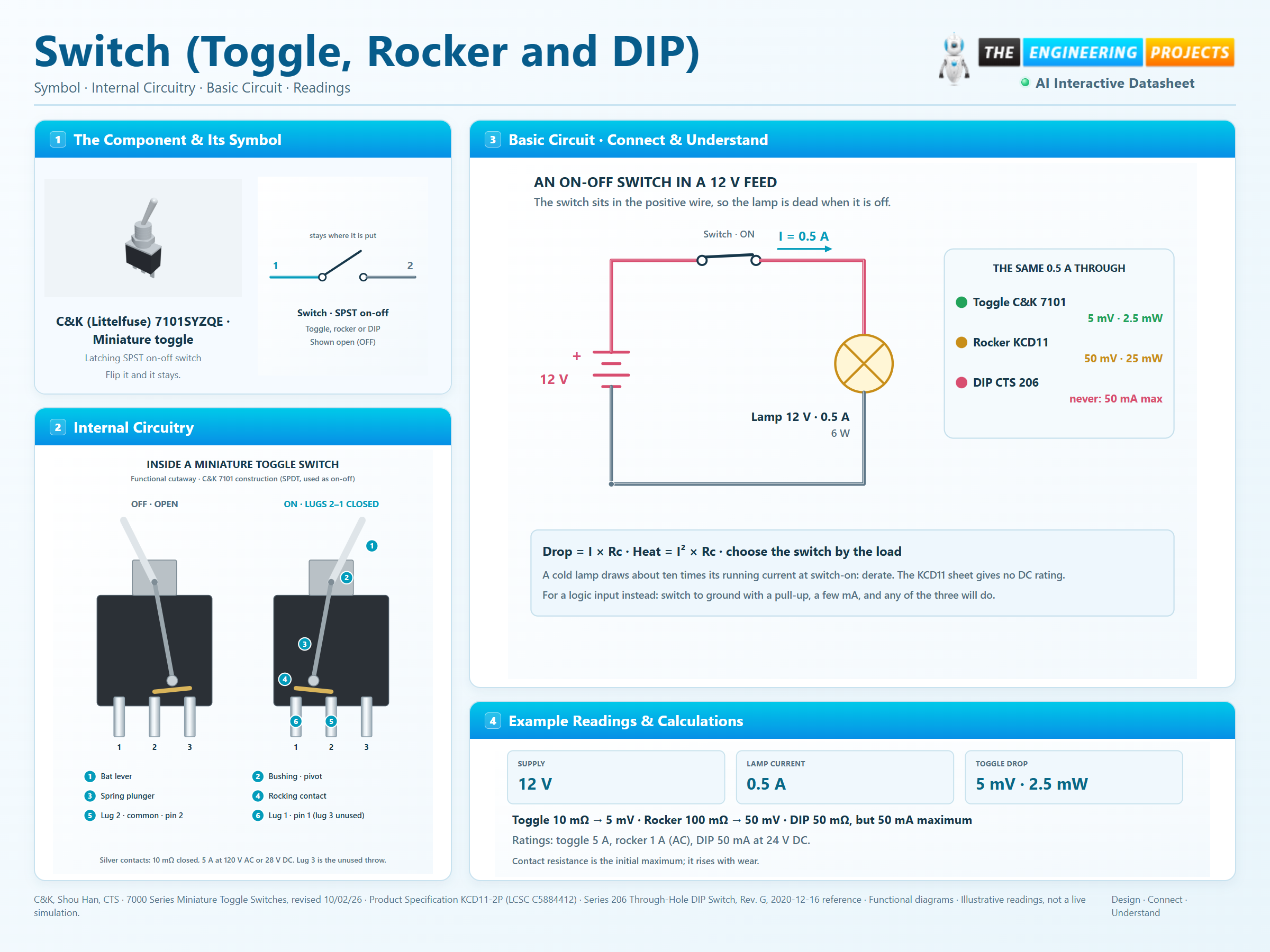
3 stages · Explore one step at a time
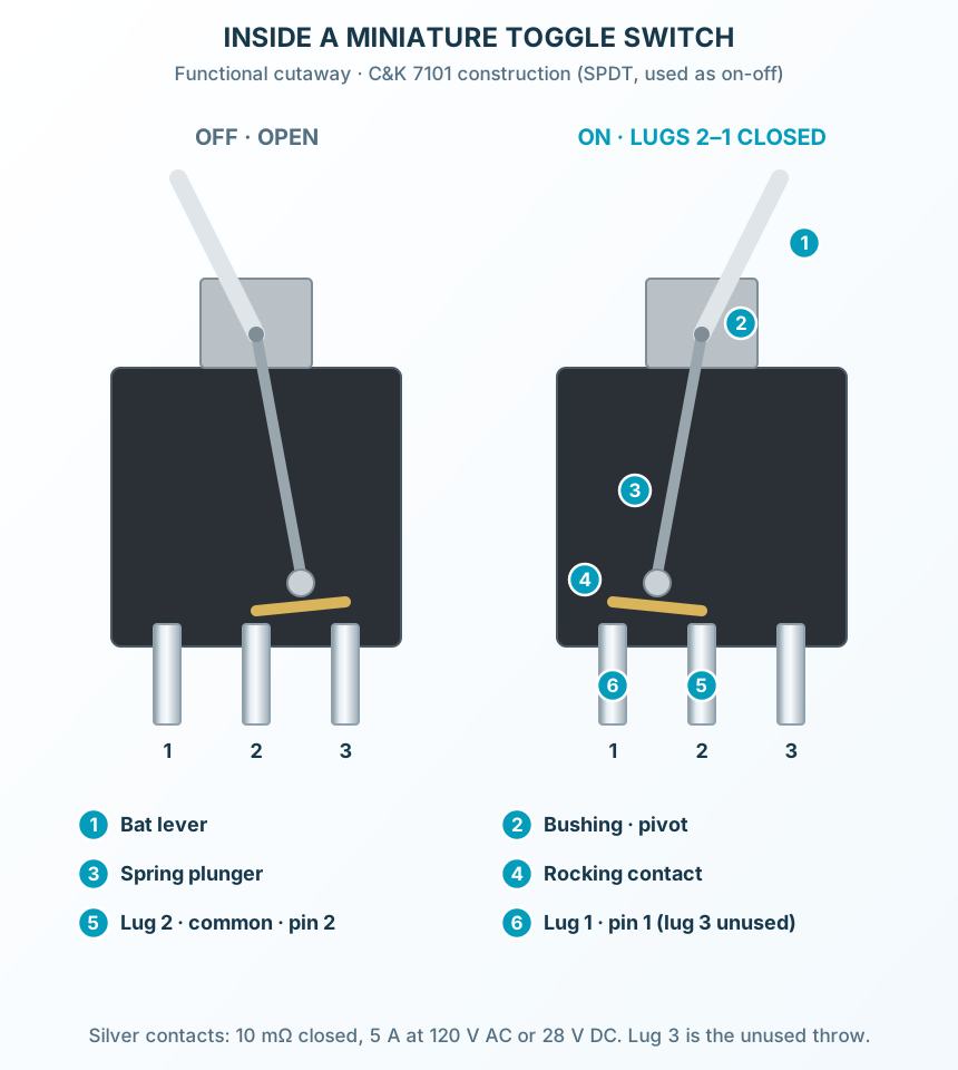
Inside each switch a spring-loaded contact rests in one of two stable positions; moving the lever, rocker or slider past the middle snaps it into the other.
In the ON position the moving contact presses on both terminals: 10 mΩ for the silver toggle contacts, 100 mΩ for the rocker, 50 mΩ for the DIP slide.
In the OFF position the terminals are separated by insulation: ≥ 10⁹ Ω for the toggle, ≥ 100 MΩ at 500 V DC for the rocker, ≥ 1000 MΩ for the DIP switch.
Supply, switch in the positive wire, lamp, return.
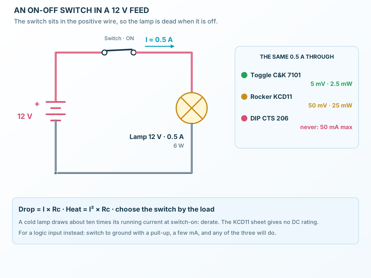
Follow the component values and pin connections
Put the switch between the supply’s positive terminal and the load.
0.5 A at 12 V suits the toggle or rocker, never the DIP switch.
For a mode input: switch to ground, pull-up to the supply, 50 mA is plenty.
Lever, spring plunger, rocking contact and lugs.
Select a stage to see its role and connections
The lever pivots in the bushing; inside, a spring plunger rides on the moving contact.
Past the centre, the spring tips the contact over: it never rests half-way.
The centre lug is common; one end lug closes with it in each position.
Signal names, electrical functions and connection guidance
Scroll within the table to see all columns and rows.
| Pin | Signal | Type | Function & connection |
|---|---|---|---|
| 1 | Contact terminal 1 | Toggle: end lug 1 (C&K) or terminal 3 (E-Switch). Rocker: one tab. DIP switch: pin 1, the square pad. Panel switches reach the board on header pad 1.Connection guidanceConnect to the supply or signal being switched. A switch has no polarity; respect the voltage and current rating of the switch chosen. | |
| 2 | Contact terminal 2 | Toggle: terminal 2, the centre (common) one. Rocker: the other tab. DIP switch: pin 2. Header pad 2.Connection guidanceConnect to the load, or to the input being configured. Closed: 10 mΩ C&K toggle, 20 mΩ / 10 mΩ / 50 mΩ E-Switch 200 / 100 / ST4, 100 mΩ rocker, 50 mΩ DIP (maximum, initial). |
No pins match these filters. Try another signal name or reset the filters.
Manufacturer scope and page conventions
Scroll within the table to see all columns and rows.
| Parameter | Value | Conditions / notes |
|---|---|---|
| Reference parts | C&K (Littelfuse) 7101SYZQE · Shou Han KCD11-2P · CTS 206-1S · E-Switch 200MSP6T1B1M2QE · 100SP1T1B1M1QE · ST4SP2DT1C2 | One sheet each |
| Contact form | SPST on-off, latching | The C&K and E-Switch 200 / 100 toggles are SPDT: the common terminal 2 and one end terminal make the on-off switch |
| Terminal 1 | Toggle lug 1 (E-Switch: terminal 3) · rocker tab · DIP pin 1 (square) | ProTech pin 1 · footprint pad 1 |
| Terminal 2 | Toggle terminal 2 (common) · rocker tab · DIP pin 2 | ProTech pin 2 · footprint pad 2 |
| Panel switches | Toggles and rocker wired to a 2-pin header | Their own lugs are not PCB pins |
| Proteus symbol | SWITCH | 2 pins; ProTech’s Toggle Switch models it |
No specifications match. Try a parameter name or a unit.
A panel switch’s wires go to the header; the header is what the PCB carries.
From each manufacturer’s sheet · the numbers ProTech’s model and checks use
Scroll within the table to see all columns and rows.
| Specification | C&K (Littelfuse) 7101SYZQE | Shou Han KCD11-2P | CTS 206-1S | E-Switch 200MSP6T1B1M2QE | E-Switch 100SP1T1B1M1QE | E-Switch ST4SP2DT1C2 |
|---|---|---|---|---|---|---|
| Contact rating (resistive) | 5 A at 120 V AC or 28 V DC; 2 A at 250 V AC (silver) | 1 A at 250 V AC (no DC rating in the sheet) | 50 mA at 24 V DC switching; 100 mA or 50 V DC carrying | 3 A at 120 V AC or 28 V DC; 1 A at 250 V AC (silver) | 5 A at 120 V AC or 28 V DC; 2 A at 250 V AC (silver) | 20 A at 6–30 V DC; 16(8) A at 125/250 V AC |
| Minimum load | gold contacts: 0.4 VA max at 20 V | not in datasheet | not in datasheet | gold contacts: 0.4 VA max at 20 V | gold contacts: 0.4 VA max at 20 V | not in datasheet |
| Contact resistance | 10 mΩ maximum (initial) | 100 mΩ maximum (initial) | 50 mΩ maximum (initial) | 20 mΩ maximum (initial) | 10 mΩ maximum (initial) | 50 mΩ maximum (initial) |
| Insulation resistance | ≥ 10⁹ Ω | ≥ 100 MΩ at 500 V DC | ≥ 1000 MΩ | ≥ 1000 MΩ | ≥ 1000 MΩ | ≥ 50 MΩ |
| Dielectric strength | 1000 V rms | 1500 V AC between terminals | 500 V AC for 1 min | 1000 V rms | 1000 V rms | 1500 V rms |
| Operation | lever, two positions 25° each side | rocker, two positions (O and —) | slide, two positions | lever, two positions 25° each side | lever, two positions 25° each side; torque max 5 kg·cm | 17 mm metal bat, two positions (OFF-ON) |
| Travel | lever 10.67 mm above the bushing | rocker 12 × 6.3 mm, about 3 mm proud | travel 2.03 mm | lever 9.40 mm above the bushing | lever 10.41 mm above the bushing | bat 17.00 mm above the bushing |
| Life | 100 000 electrical cycles at full load | 10 000 mechanical cycles | 10 000 cycles at 50 mA, 24 V DC | 30 000 mechanical, 6 000 at full load | 40 000 mechanical, 6 000 at full power | 10 000 electrical cycles |
| Contact bounce | not in the sheet | not in the sheet | not in the sheet | not in the sheet | not in the sheet | not in the sheet |
| Operating temperature | −30 to +85 °C | −25 to +85 °C | −55 to +85 °C | −40 to +85 °C | −40 to +85 °C | −10 to +55 °C |
| Size | case 12.70 × 6.86 mm, 1/4-40 bushing, hex nut | bezel 15 × 10.5 mm, panel cut-out 14 × 8.8 mm | 9.78 × 3.96 mm, 7.6 mm high | case 8.13 × 8.64 mm, 10-48 bushing 5.59 mm, nut 7.00 mm A/F | case 12.70 × 8.89 mm, 1/4-40 bushing 8.89 mm | case 28.80 × 21.00 mm, 15/32-32 bushing Ø12 mm, IP68 |
| Terminals | 4.70 mm (SPDT; pins 2 common and 1 used for ON-OFF) | 5.0 mm (2 pins, snap-in panel mount) | 7.62 mm row spacing (2 pins) | 2.54 mm (PC pins 1-2-3; pins 2 common and 3 used for OFF-ON) | 4.70 mm (solder lugs 1-2-3; pins 2 common and 3 used for ON-OFF) | 1/4 in quick-connect tabs (panel mount) |
| Look | chrome bat lever, nickel-plated hex nut and bushing, dark case | black bezel and rocker, O and bar marks | blue housing, white slider, ON arrow | side view: case, nickel bushing and nut, chrome bat lever; its tip lit red OFF, green ON (ProTech's display; the real bat is plain) | side view: case, nickel bushing and nut, chrome bat lever; its tip lit red OFF, green ON (ProTech's display; the real bat is plain) | side view: case, nickel bushing and nut, chrome bat lever; its tip lit red OFF, green ON (ProTech's display; the real bat is plain) |
No specifications match. Try a parameter name or a unit.
Contact resistance is the initial maximum; it rises with wear and contamination. Ratings are for resistive loads.
The same numbers drive the simulator, its checks and this page
Scroll within the table to see all columns and rows.
| Parameter | Value | Conditions / notes |
|---|---|---|
| Closed | Rc of the switch chosen, between pins 1 and 2 | 10 mΩ toggle · 100 mΩ rocker · 50 mΩ DIP · 20 mΩ / 10 mΩ / 50 mΩ E-Switch 200 / 100 / ST4 |
| Open | No branch | Insulation resistance not modelled |
| Rating check | Warns above the switch’s current or voltage | 5 A / 28 V · 1 A / 250 V · 50 mA / 24 V · 3 A / 28 V · 5 A / 28 V · 20 A / 30 V |
| Position | Saved with the circuit | A click or Enter flips it while running |
| Size | Drawn at true size | Toggle 12.70 × 6.86 mm, rocker 15 × 10.5 mm, DIP 9.78 × 3.96 mm, E-Switch toggles 8.13, 12.70 and 28.80 mm wide |
| LED toggle switch | The E-Switch 200, 100 and ST4 (small, medium, large) | Its lit tip, red OFF and green ON, is ProTech’s display; the real bat is plain |
No specifications match. Try a parameter name or a unit.
Change the switch in Properties: the drawing, rating, contact resistance and PCB footprint follow it.
Toggle or rocker in the positive wire
Scroll within the table to see all columns and rows.
| Parameter | Value | Conditions / notes |
|---|---|---|
| Toggle drop | 5 mV | 0.5 A × 10 mΩ |
| Toggle contact heating | 2.5 mW | (0.5 A)² × 10 mΩ |
| Rocker drop | 50 mV | 0.5 A × 100 mΩ |
| Rocker contact heating | 25 mW | (0.5 A)² × 100 mΩ |
| Rocker on DC | Check first | The KCD11 sheet gives 1 A at 250 V AC and no DC rating |
| DIP switch | Never | Rated 50 mA switching; use it for logic inputs |
No specifications match. Try a parameter name or a unit.
Lamps draw about ten times their running current when cold: derate the switch for them.
7101SYZQE · Miniature toggle
Scroll within the table to see all columns and rows.
| Parameter | Value | Conditions / notes |
|---|---|---|
| Toggle | case 12.70 × 6.86 mm, 1/4-40 bushing, hex nut | 4.70 mm (SPDT; pins 2 common and 1 used for ON-OFF) |
| Rocker | bezel 15 × 10.5 mm, panel cut-out 14 × 8.8 mm | 5.0 mm (2 pins, snap-in panel mount) |
| DIP switch | 9.78 × 3.96 mm, 7.6 mm high | 7.62 mm row spacing (2 pins) |
| E-Switch 200 | case 8.13 × 8.64 mm, 10-48 bushing 5.59 mm, nut 7.00 mm A/F | 2.54 mm (PC pins 1-2-3; pins 2 common and 3 used for OFF-ON) |
| E-Switch 100 | case 12.70 × 8.89 mm, 1/4-40 bushing 8.89 mm | 4.70 mm (solder lugs 1-2-3; pins 2 common and 3 used for ON-OFF) |
| E-Switch ST4 | case 28.80 × 21.00 mm, 15/32-32 bushing Ø12 mm, IP68 | 1/4 in quick-connect tabs (panel mount) |
| Header (panel switches) | 2.54 mm pitch, Ø1 mm drill | KiCad PinHeader_1x02_P2.54mm_Vertical |
| DIP footprint | 7.62 mm row spacing, Ø0.8 mm drill | KiCad SW_DIP_SPSTx01_Slide_9.78x4.72mm_W7.62mm_P2.54mm |
No specifications match. Try a parameter name or a unit.
Footprints are KiCad’s, the same as ProTech’s PCB page.
No matching rowsTry a pin name, parameter, unit or test condition, or reset the filters.
A toggle or rocker in the positive feed of a battery or adapter: the classic on-off switch of a project box.
Manufacturer application guideA toggle or DIP switch to ground with a pull-up selects a mode the program reads at start-up.
Manufacturer application guideDIP switches set addresses and options on boards; each position is one bit, 50 mA at most.
Manufacturer application guideFind Switch (Toggle, Rocker and DIP) in the Components Library to place its schematic symbol and connect its pins.
Working switch example available in ProTechOpen ProTech