Real View
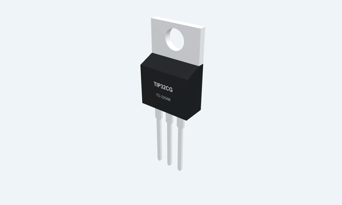
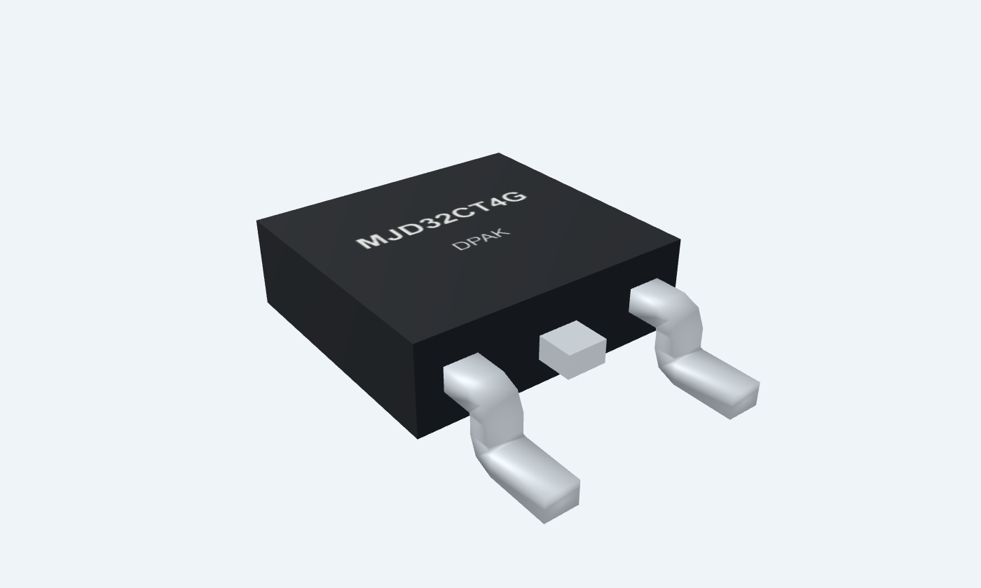
Control the positive supply. Define the base return.
TIP32C is a 100 V, 3 A PNP bipolar power transistor for amplification and switching. Base current controls collector current, while the actual operating point is limited by voltage, heat and safe operating area. It is a single transistor, not a Darlington pair. The selected onsemi TIP32CG TO-220 uses base 1, collector 2 and emitter 3. MJD32CT4G is the documented electrically similar DPAK alternative, with the same functions and a surface-mount collector pad. Its power ratings and leakage limits are separate from the through-hole part. The example uses a 12 V positive-side switch, a 100 Ω resistor load and a source-referenced driver that selects 12 V for off or 7 V for on. The driver sinks base current through 330 Ω; a 10 kΩ base-emitter resistor defines the off state.
Select a pin to explore its connection
Click a lead or use the arrow keys. Front view · B1, C2, E3 · tab = C
Current-driven control junction.
Use the example’s 330 Ω base resistor and 10 kΩ base-emitter return.
The driver must sink base current. A 3.3 V output cannot directly turn off a 12 V high-side transistor.
Load terminal, also connected to the metal tab.
Connect the 100 Ω resistor load to this terminal.
The exposed tab is electrically live; insulate it when required.
Positive supply and base-drive reference.
Connect emitter to +12 V. Pull base up to emitter to turn off.
Front view: B1, C2, E3; tab is collector.
The 3 A limit does not promise 3 A from any control output. The saturation test uses 375 mA base current, and allowable dissipation depends on case temperature or the specified PCB.
TIP32CG · TO-220AB
| Property | Details |
|---|---|
| Manufacturer | onsemi |
| Part number | TIP32CG |
| Package | TO-220AB |
| Connections | 3 pins |
| Mounting | Through-hole |
| Lead pitch | 2.54 mm |
| Package code | 221A style 1 |
| Thermal reference | 40 W at case 25°C; 2 W at ambient 25°C |
Two separately documented selections
Scroll sideways to see all columns.
| Parameter | Value | Conditions / notes |
|---|---|---|
| Through-hole | TIP32CG · TO-220 | TIP31A/D Rev. 17, June 2024 |
| Surface-mount | MJD32CT4G · DPAK | MJD31/D Rev. 21, May 2026 |
| Polarity | PNP | Manufacturer tables use magnitudes; reverse voltage/current signs for PNP |
| Terminals | B1 · C2 · E3 | Tab/contact 4 is electrically collector |
| SMD relationship | Electrically similar manufacturer counterpart | Different power and leakage limits; check the selected package |
No specifications match. Try a parameter name or a unit.
Pin function is preserved when the package changes.
Magnitudes; individual stress limits
Scroll sideways to see all columns.
| Parameter | Value | Conditions / notes |
|---|---|---|
| Collector-emitter / collector-base | 100 / 100 V | Selected C-voltage grades only |
| Emitter-base reverse voltage | 5 V | Do not apply a reverse drive without limiting it |
| DC / peak collector current | 3 / 5 A | Thermal and pulse restrictions also apply |
| Base current | 1 A | Absolute maximum |
| Junction and storage | −65 to +150°C | Both selected references |
No specifications match. Try a parameter name or a unit.
These are not simultaneous operating targets.
TC 25°C; pulse ≤300 µs, duty ≤2%
Scroll sideways to see all columns.
| Parameter | Value | Conditions / notes |
|---|---|---|
| hFE at IC 1 A | 25 minimum | VCE 4 V |
| hFE at IC 3 A | 10–50 | VCE 4 V |
| Collector-emitter saturation | 1.2 V maximum | IC 3 A; IB 375 mA |
| Base-emitter on voltage | 1.8 V maximum | IC 3 A; VCE 4 V |
| Current gain-bandwidth | 3 MHz minimum | IC 500 mA; VCE 10 V; test 1 MHz |
| Small-signal gain | 20 minimum | IC 500 mA; VCE 10 V; 1 kHz |
No specifications match. Try a parameter name or a unit.
Active-region gain does not replace a saturation base-current budget.
Maximum magnitudes at TC 25°C
Scroll sideways to see all columns.
| Parameter | Value | Conditions / notes |
|---|---|---|
| TO-220 ICEO | 0.3 mA | VCE 60 V; base open |
| DPAK ICEO | 50 µA | VCE 60 V; base open |
| TO-220 ICES | 200 µA | VCE 100 V; VEB 0 |
| DPAK ICES | 20 µA | VCE 100 V; VEB 0 |
| Emitter leakage | 1 mA | VBE reverse 5 V; collector open |
No specifications match. Try a parameter name or a unit.
Leakage can matter even when the load is meant to be off.
The boundary condition changes the rating
Scroll sideways to see all columns.
| Parameter | Value | Conditions / notes |
|---|---|---|
| TO-220 power / derating | 40 W / 0.32 W per °C | Case 25°C / above 25°C |
| TO-220 ambient power | 2 W | Ambient 25°C; derate 0.016 W/°C |
| TO-220 RθJC / RθJA | 3.125 / 62.5°C/W | Maximum reference values |
| DPAK power / derating | 15 W / 0.12 W per °C | Case 25°C / above 25°C |
| DPAK ambient power | 1.56 W | FR-4, 165 mm², 1 oz copper; derate 0.012 W/°C |
| DPAK RθJC / RθJA | 8.3 / 80°C/W | Specified mounting and minimum-pad conditions |
| Safe operating area | Check manufacturer curves | Voltage, current, duration and starting temperature together |
No specifications match. Try a parameter name or a unit.
The package image is not a heatsink rating.
Explicit illustrative assumptions
Scroll sideways to see all columns.
| Parameter | Value | Conditions / notes |
|---|---|---|
| Load | 100 Ω, at least 3 W | Collector to ground |
| Base resistor / return | 330 Ω / 10 kΩ | Return resistor goes from base to emitter |
| Buffered driver | 12 V off / 7 V on | Level-shifted; sinks base current |
| Assumed junctions | |VBE| 0.8 V; |VCE| 0.2 V | Teaching assumptions, not guaranteed test points |
| Base current | 12.65 mA | (5−0.8)/330−0.8/10000 |
| Collector current / forced ratio | 118 mA / 9.33 | (12−0.2)/100; IC/IB |
| Transistor / load loss | 33.7 mW / 1.392 W | Include base contribution; allow resistor thermal margin |
No specifications match. Try a parameter name or a unit.
Inductive loads require a suitable clamp and a separate transient check.
Select a pin for its function, connection guidance and electrical notes.
Follow the labeled connections and functional stages
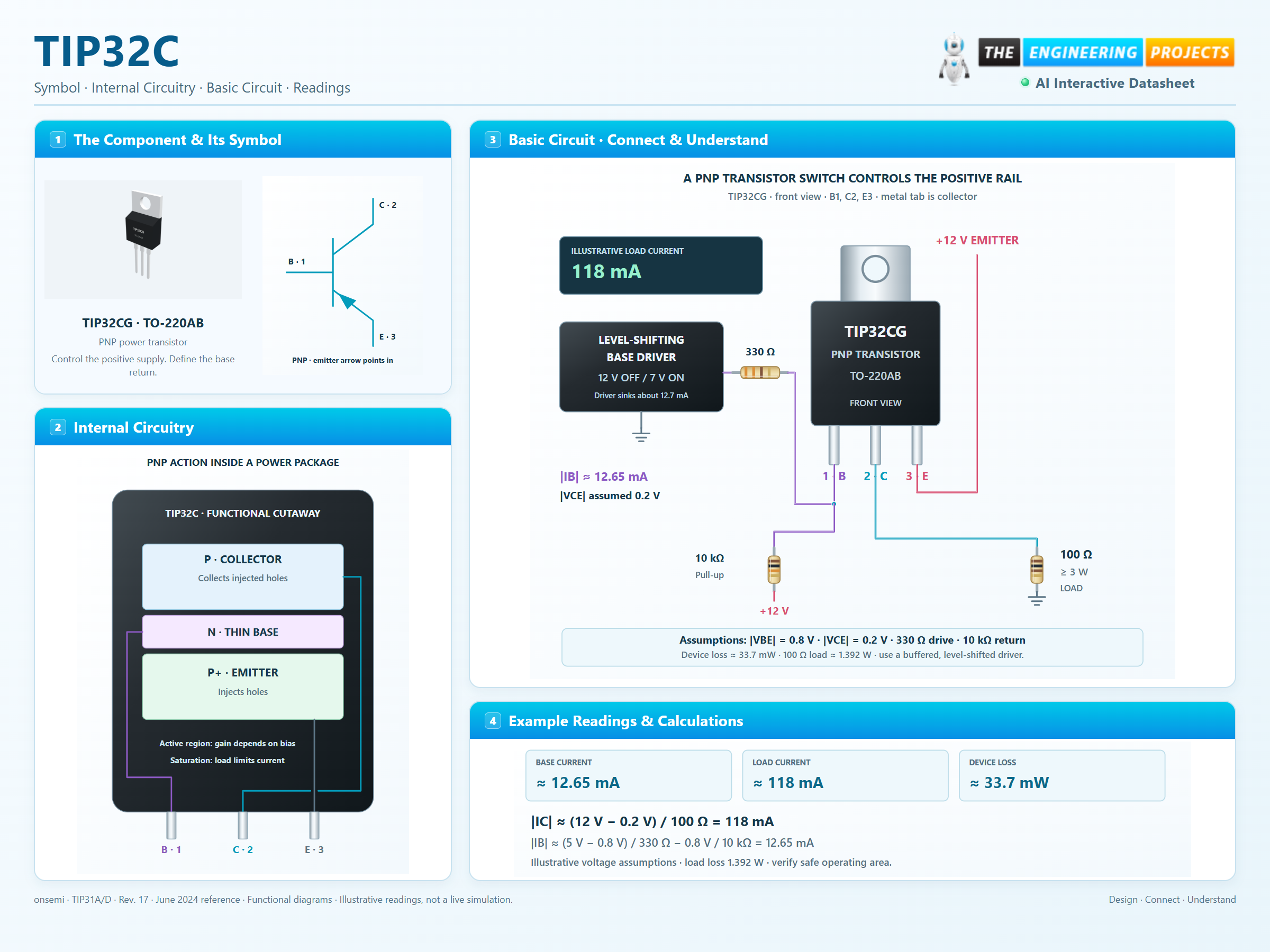
3 stages · Explore one step at a time
Pull base below emitter through the resistor.
Conventional current flows from emitter to collector.
The base-emitter return defines off; switching speed depends on drive and stored charge.
The supply, driver, load and return are shown explicitly.
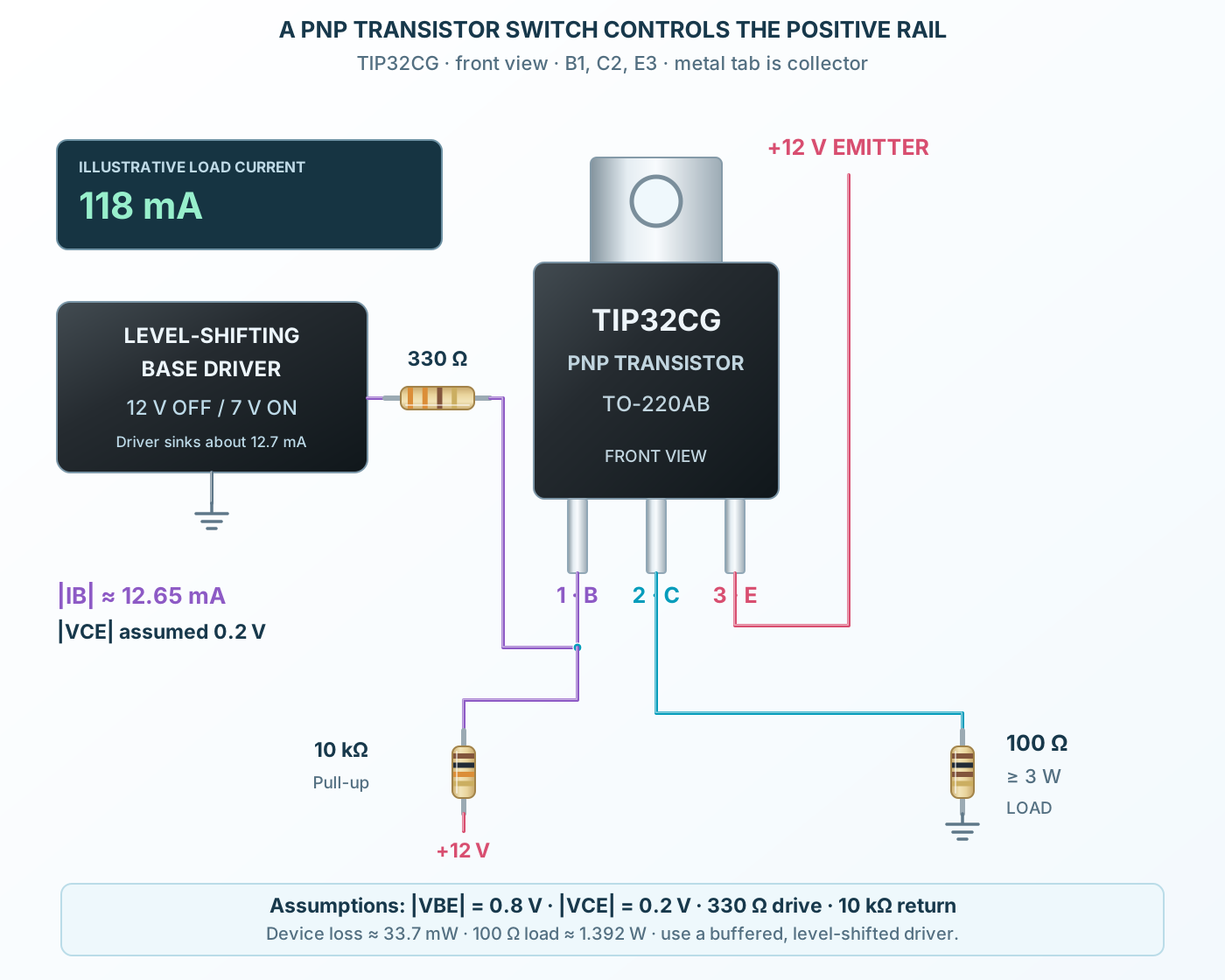
Follow the component values and pin connections
100 Ω from collector to ground.
330 Ω limits drive current; 10 kΩ returns base to emitter.
Use at least a 3 W load resistor and check transistor safe operating area.
Three semiconductor regions, two junctions and one controlled current path.
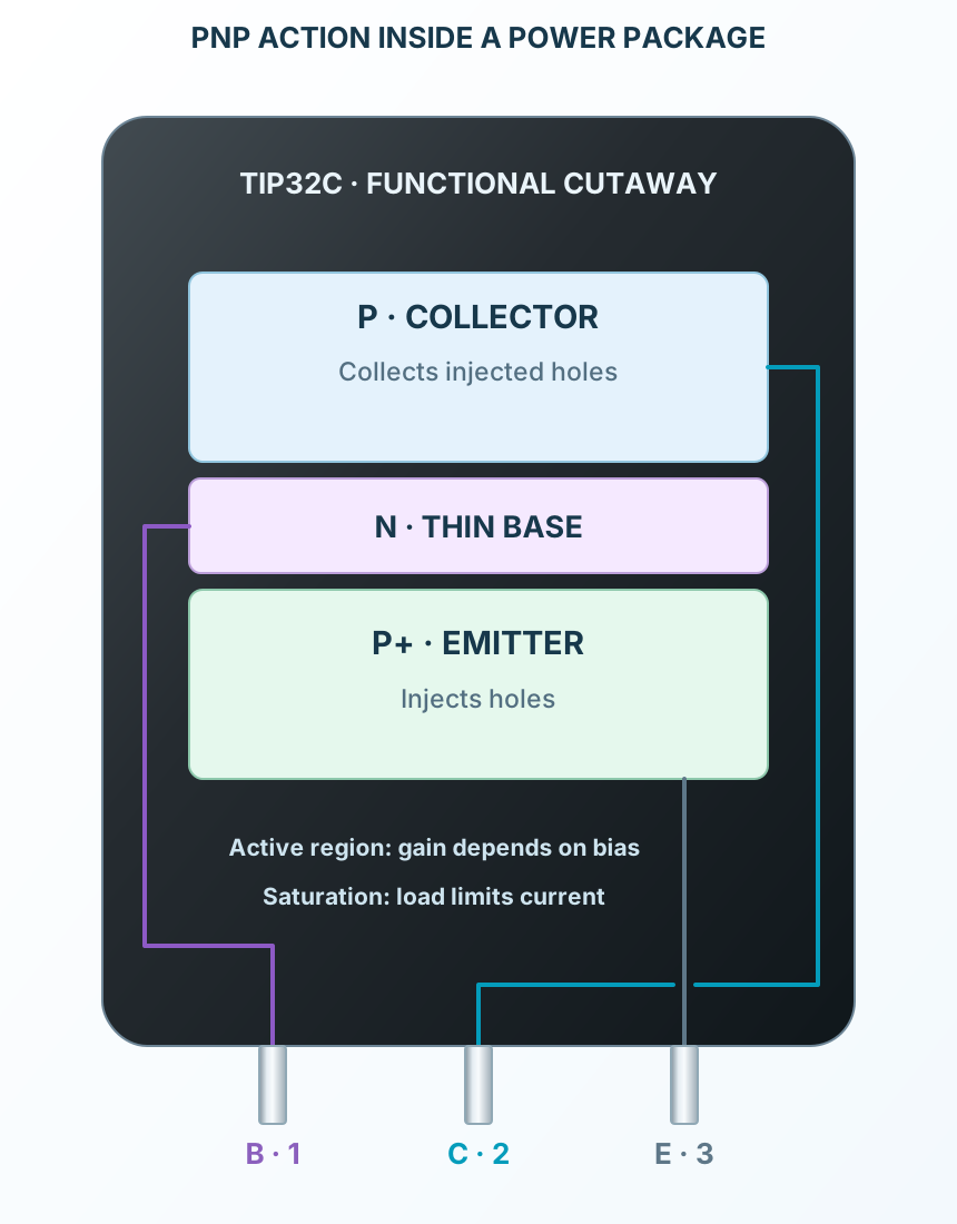
Select a stage to see its role and connections
The thin base controls carrier transport.
The collector supports off-state voltage and carries load current.
The emitter injects carriers when the base junction is forward biased.
Signal names, electrical functions and connection guidance
Scroll within the table to see all columns and rows.
| Pin | Signal | Type | Function & connection |
|---|---|---|---|
| B | Base | Current-driven control junction.Connection guidanceUse the example’s 330 Ω base resistor and 10 kΩ base-emitter return. The driver must sink base current. A 3.3 V output cannot directly turn off a 12 V high-side transistor. | |
| C | Collector | Load terminal, also connected to the metal tab.Connection guidanceConnect the 100 Ω resistor load to this terminal. The exposed tab is electrically live; insulate it when required. | |
| E | Emitter | Positive supply and base-drive reference.Connection guidanceConnect emitter to +12 V. Pull base up to emitter to turn off. Front view: B1, C2, E3; tab is collector. |
No pins match these filters. Try another signal name or reset the filters.
Two separately documented selections
Scroll within the table to see all columns and rows.
| Parameter | Value | Conditions / notes |
|---|---|---|
| Through-hole | TIP32CG · TO-220 | TIP31A/D Rev. 17, June 2024 |
| Surface-mount | MJD32CT4G · DPAK | MJD31/D Rev. 21, May 2026 |
| Polarity | PNP | Manufacturer tables use magnitudes; reverse voltage/current signs for PNP |
| Terminals | B1 · C2 · E3 | Tab/contact 4 is electrically collector |
| SMD relationship | Electrically similar manufacturer counterpart | Different power and leakage limits; check the selected package |
No specifications match. Try a parameter name or a unit.
Pin function is preserved when the package changes.
Magnitudes; individual stress limits
Scroll within the table to see all columns and rows.
| Parameter | Value | Conditions / notes |
|---|---|---|
| Collector-emitter / collector-base | 100 / 100 V | Selected C-voltage grades only |
| Emitter-base reverse voltage | 5 V | Do not apply a reverse drive without limiting it |
| DC / peak collector current | 3 / 5 A | Thermal and pulse restrictions also apply |
| Base current | 1 A | Absolute maximum |
| Junction and storage | −65 to +150°C | Both selected references |
No specifications match. Try a parameter name or a unit.
These are not simultaneous operating targets.
TC 25°C; pulse ≤300 µs, duty ≤2%
Scroll within the table to see all columns and rows.
| Parameter | Value | Conditions / notes |
|---|---|---|
| hFE at IC 1 A | 25 minimum | VCE 4 V |
| hFE at IC 3 A | 10–50 | VCE 4 V |
| Collector-emitter saturation | 1.2 V maximum | IC 3 A; IB 375 mA |
| Base-emitter on voltage | 1.8 V maximum | IC 3 A; VCE 4 V |
| Current gain-bandwidth | 3 MHz minimum | IC 500 mA; VCE 10 V; test 1 MHz |
| Small-signal gain | 20 minimum | IC 500 mA; VCE 10 V; 1 kHz |
No specifications match. Try a parameter name or a unit.
Active-region gain does not replace a saturation base-current budget.
Maximum magnitudes at TC 25°C
Scroll within the table to see all columns and rows.
| Parameter | Value | Conditions / notes |
|---|---|---|
| TO-220 ICEO | 0.3 mA | VCE 60 V; base open |
| DPAK ICEO | 50 µA | VCE 60 V; base open |
| TO-220 ICES | 200 µA | VCE 100 V; VEB 0 |
| DPAK ICES | 20 µA | VCE 100 V; VEB 0 |
| Emitter leakage | 1 mA | VBE reverse 5 V; collector open |
No specifications match. Try a parameter name or a unit.
Leakage can matter even when the load is meant to be off.
The boundary condition changes the rating
Scroll within the table to see all columns and rows.
| Parameter | Value | Conditions / notes |
|---|---|---|
| TO-220 power / derating | 40 W / 0.32 W per °C | Case 25°C / above 25°C |
| TO-220 ambient power | 2 W | Ambient 25°C; derate 0.016 W/°C |
| TO-220 RθJC / RθJA | 3.125 / 62.5°C/W | Maximum reference values |
| DPAK power / derating | 15 W / 0.12 W per °C | Case 25°C / above 25°C |
| DPAK ambient power | 1.56 W | FR-4, 165 mm², 1 oz copper; derate 0.012 W/°C |
| DPAK RθJC / RθJA | 8.3 / 80°C/W | Specified mounting and minimum-pad conditions |
| Safe operating area | Check manufacturer curves | Voltage, current, duration and starting temperature together |
No specifications match. Try a parameter name or a unit.
The package image is not a heatsink rating.
Explicit illustrative assumptions
Scroll within the table to see all columns and rows.
| Parameter | Value | Conditions / notes |
|---|---|---|
| Load | 100 Ω, at least 3 W | Collector to ground |
| Base resistor / return | 330 Ω / 10 kΩ | Return resistor goes from base to emitter |
| Buffered driver | 12 V off / 7 V on | Level-shifted; sinks base current |
| Assumed junctions | |VBE| 0.8 V; |VCE| 0.2 V | Teaching assumptions, not guaranteed test points |
| Base current | 12.65 mA | (5−0.8)/330−0.8/10000 |
| Collector current / forced ratio | 118 mA / 9.33 | (12−0.2)/100; IC/IB |
| Transistor / load loss | 33.7 mW / 1.392 W | Include base contribution; allow resistor thermal margin |
No specifications match. Try a parameter name or a unit.
Inductive loads require a suitable clamp and a separate transient check.
No matching rowsTry a pin name, parameter, unit or test condition, or reset the filters.
Control modest DC loads with explicit base drive and thermal checks.
Manufacturer application guideUse the transistor in its active region within safe operating area.
Manufacturer application guidePair NPN and PNP devices with suitable bias and protection.
Manufacturer application guideFind TIP32C in the Components Library to place its schematic symbol and connect its pins.
Reference page · circuit simulation model not yet availableOpen ProTech