TM1637Six-digit LED driver with key scanning
Two control wires. Six digit positions. A built-in key scanner.
TM1637 integrates a six-digit LED driver, six bytes of display RAM and a 16-key scanner in a 20-pin IC. It drives common-anode displays: GRID outputs source the digit current and SEG outputs sink the individual segment currents. A host updates the display through CLK and bidirectional DIO. The interface resembles I²C electrically, but it has no slave address and transfers each byte least-significant bit first. The host must release DIO for the acknowledgement clock. This reference covers the DIP-20 and SOP-20 packages in Titan Micro V2.4. Its example uses a 5 V host, six digits, two 10 kΩ pull-ups and local supply bypassing. Eight non-linear PWM settings adjust brightness; digit bytes directly select segments rather than decoding decimal numbers.
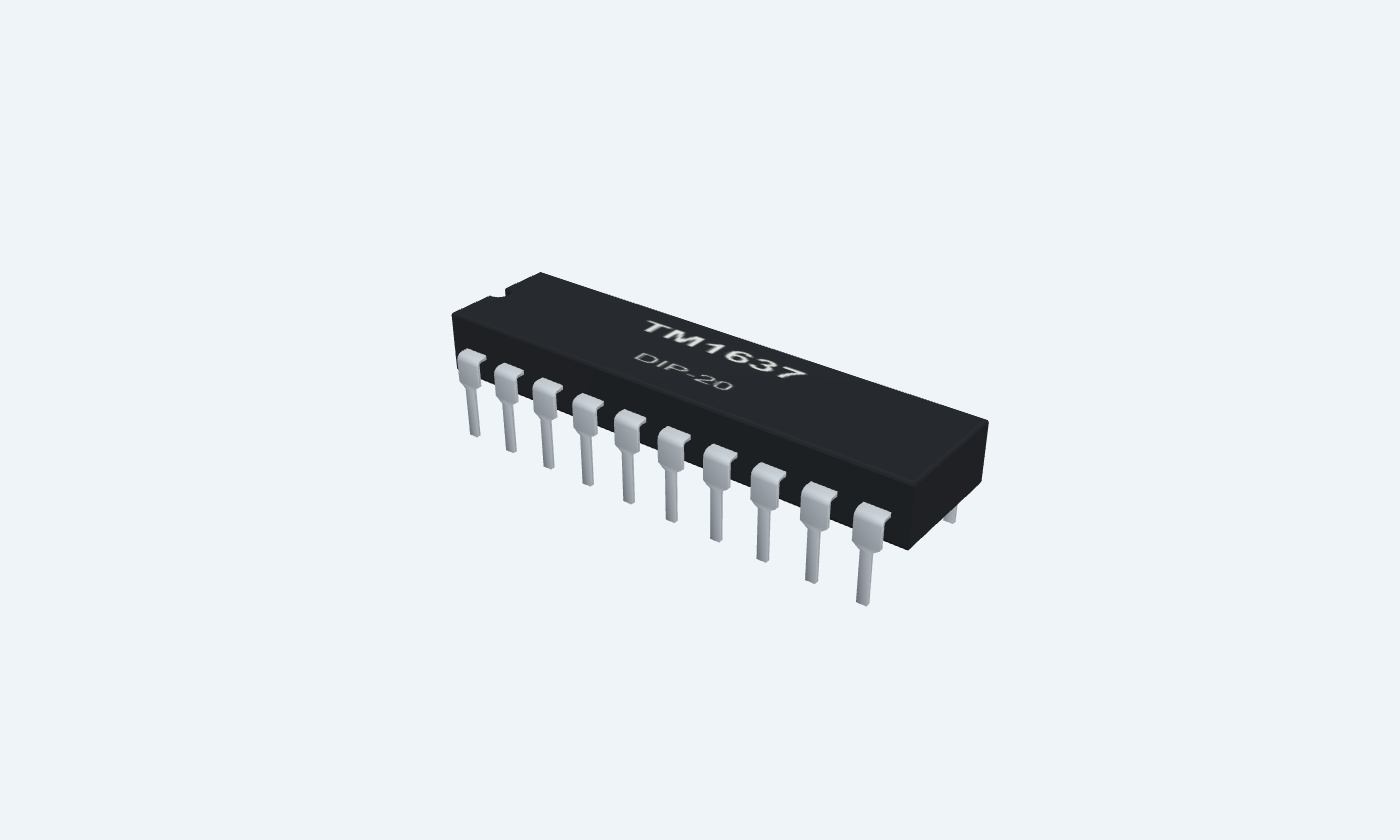
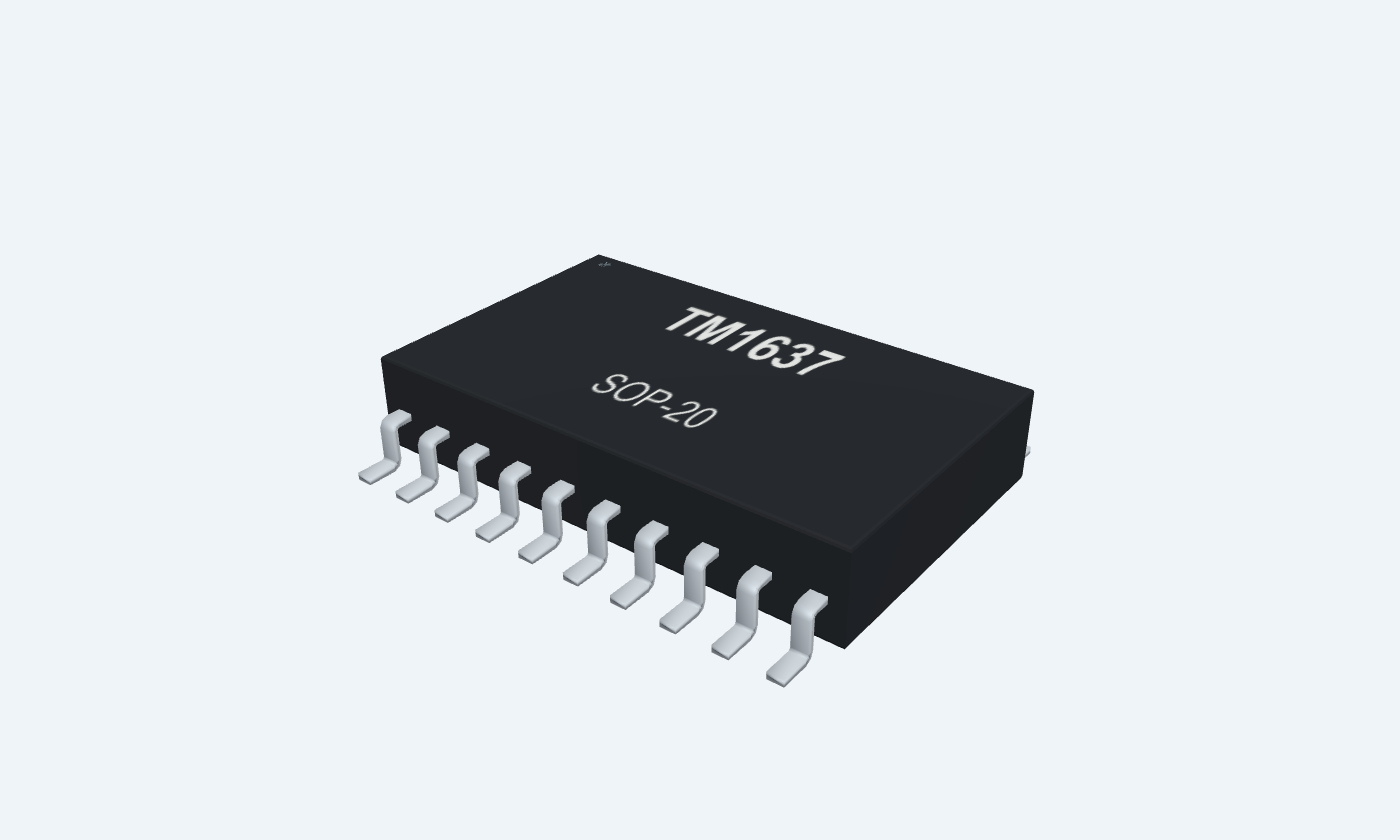

20Physical pins
TM1637DIP-20
Manufacturer-referencedTitan Micro Electronics
Pin diagram
Select a pin to explore its connection
Highlight
TM1637DIP-20Top view
TM1637SOP-20Top view
Click a lead or use the arrow keys. Top view
PIN 1 · Ground
GroundGND
Function
Supply and segment-current return.
How to connect
Connect to the common ground and the bypass capacitors.
PIN 2 · Segments / key scan
Open-drain sink / scanSEG1 / KS1
Function
Sinks current from segment 1; also provides key-scan timing.
How to connect
Connect to the shared cathodes of segment A across the display.
Electrical note
A set display bit enables the corresponding sink during the selected grid slot.
PIN 3 · Segments / key scan
Open-drain sink / scanSEG2 / KS2
Function
Sinks current from segment 2; also provides key-scan timing.
How to connect
Connect to the shared cathodes of segment B across the display.
Electrical note
A set display bit enables the corresponding sink during the selected grid slot.
PIN 4 · Segments / key scan
Open-drain sink / scanSEG3 / KS3
Function
Sinks current from segment 3; also provides key-scan timing.
How to connect
Connect to the shared cathodes of segment C across the display.
Electrical note
A set display bit enables the corresponding sink during the selected grid slot.
PIN 5 · Segments / key scan
Open-drain sink / scanSEG4 / KS4
Function
Sinks current from segment 4; also provides key-scan timing.
How to connect
Connect to the shared cathodes of segment D across the display.
Electrical note
A set display bit enables the corresponding sink during the selected grid slot.
PIN 6 · Segments / key scan
Open-drain sink / scanSEG5 / KS5
Function
Sinks current from segment 5; also provides key-scan timing.
How to connect
Connect to the shared cathodes of segment E across the display.
Electrical note
A set display bit enables the corresponding sink during the selected grid slot.
PIN 7 · Segments / key scan
Open-drain sink / scanSEG6 / KS6
Function
Sinks current from segment 6; also provides key-scan timing.
How to connect
Connect to the shared cathodes of segment F across the display.
Electrical note
A set display bit enables the corresponding sink during the selected grid slot.
PIN 8 · Segments / key scan
Open-drain sink / scanSEG7 / KS7
Function
Sinks current from segment 7; also provides key-scan timing.
How to connect
Connect to the shared cathodes of segment G across the display.
Electrical note
A set display bit enables the corresponding sink during the selected grid slot.
PIN 9 · Segments / key scan
Open-drain sink / scanSEG8 / KS8
Function
Sinks current from segment 8; also provides key-scan timing.
How to connect
Connect to the shared cathodes of segment DP across the display.
Electrical note
A set display bit enables the corresponding sink during the selected grid slot.
PIN 10 · Common-anode digits
High-side sourceGRID6
Function
Drives the common anode of digit 6.
How to connect
Connect to the common anode of display digit 6.
Electrical note
Use common-anode LEDs; these outputs are not logic-level GPIO.
PIN 11 · Common-anode digits
High-side sourceGRID5
Function
Drives the common anode of digit 5.
How to connect
Connect to the common anode of display digit 5.
Electrical note
Use common-anode LEDs; these outputs are not logic-level GPIO.
PIN 12 · Common-anode digits
High-side sourceGRID4
Function
Drives the common anode of digit 4.
How to connect
Connect to the common anode of display digit 4.
Electrical note
Use common-anode LEDs; these outputs are not logic-level GPIO.
PIN 13 · Common-anode digits
High-side sourceGRID3
Function
Drives the common anode of digit 3.
How to connect
Connect to the common anode of display digit 3.
Electrical note
Use common-anode LEDs; these outputs are not logic-level GPIO.
PIN 14 · Common-anode digits
High-side sourceGRID2
Function
Drives the common anode of digit 2.
How to connect
Connect to the common anode of display digit 2.
Electrical note
Use common-anode LEDs; these outputs are not logic-level GPIO.
PIN 15 · Common-anode digits
High-side sourceGRID1
Function
Drives the common anode of digit 1.
How to connect
Connect to the common anode of display digit 1.
Electrical note
Use common-anode LEDs; these outputs are not logic-level GPIO.
PIN 16 · Supply
SupplyVDD
Function
Powers the logic and display drivers.
How to connect
The example uses a regulated 5 V rail with 100 nF and 100 µF bypass near the IC.
Electrical note
Electrical and timing characteristics are specified at 4.5–5.5 V; follow the purchased part revision.
PIN 17 · Two-wire controls
Bidirectional dataDIO
Function
Transfers command, display and key bytes; the IC pulls this line LOW for acknowledgement.
How to connect
Use a 10 kΩ pull-up to 5 V and an open-drain or releasable host pin.
Electrical note
Release the line for the ninth ACK clock and when reading keys; never contend with the IC output.
PIN 18 · Two-wire controls
Clock inputCLK
Function
Clocks data on rising edges.
How to connect
Use a 10 kΩ pull-up to 5 V; the example host clocks at 100 kHz.
Electrical note
This two-wire protocol is not I²C: no slave address, and bytes are sent least-significant bit first.
PIN 19 · Key inputs
Key inputK1
Function
First row input for the 8 × 2 key matrix.
How to connect
Optional keys connect to the SEG/KS scan lines as shown in the manufacturer circuit.
Electrical note
Internal nominal 10 kΩ pull-down; leave unused key inputs unconnected.
PIN 20 · Key inputs
Key inputK2
Function
Second row input for the 8 × 2 key matrix.
How to connect
Read with command 0x42; one key code is returned.
Electrical note
Combined key presses are not supported; idle key data is 0xFF.
Key specifications
The host writes one segment byte per grid position. The internal oscillator scans the digits, PWM controls brightness and the shared segment outputs also scan the optional key matrix.
Display capacity6 digits × 8 segments
Example supply5 V
Key matrix16 keys · one reported at a time
PWM settings8 non-linear levels
Package details
TM1637 · DIP-20
| Property | Details |
|---|---|
| Manufacturer | Titan Micro Electronics |
| Part number | TM1637 |
| Package | DIP-20 |
| Connections | 20 pins |
| Mounting | Through-hole |
| Lead pitch | 2.54 mm |
| Package code | DIP-20 |
| Thermal reference | See operating and package limits |
Supply and electrical conditions
Distinguish operating conditions from absolute limits
Manufacturer specifications 8 parameters
Scroll sideways to see all columns.
| Parameter | Value | Conditions / notes |
|---|---|---|
| Nominal application supply | 5 V | V2.4 reference circuit |
| Electrical/timing test supply | 4.5–5.5 V | Published characteristics use this range |
| Input HIGH / LOW | ≥0.7 × VDD / ≤0.3 × VDD | At 5 V: ≥3.5 V HIGH, ≤1.5 V LOW |
| Operating temperature | −40 to +85°C | Board and LED heating must remain within limits |
| No-load current, display OFF | 5 mA maximum | Not total LED supply current |
| Internal oscillator | 450 kHz typical | RC oscillator; display scan is automatic |
| Bypass example | 100 nF ceramic + 100 µF bulk | Place close to VDD16 / GND1 |
| Absolute limits | 7 V supply; 400 mW dissipation | Damage limits, not recommended operating settings |
No specifications match. Try a parameter name or a unit.
Use a compatible host or proper level translation; a 3.3 V HIGH is not guaranteed at a 5 V supply.
Display and key commands
Each command byte is sent LSB first
Manufacturer specifications 8 parameters
Scroll sideways to see all columns.
| Parameter | Value | Conditions / notes |
|---|---|---|
| 0x40 | Write display, auto increment | Normal mode; addresses advance through six bytes |
| 0x44 | Write display, fixed address | Send the chosen address and one byte |
| 0x42 | Read key-scan code | Release DIO for IC-to-host transfer |
| 0xC0–0xC5 | Set display address | GRID1 through GRID6 respectively |
| 0xC6 and higher | Outside display RAM | Data ignored until a valid address is selected |
| 0x80 | Display OFF | Output blanking command |
| 0x88–0x8F | Display ON + brightness | Low three bits select the PWM setting |
| Test mode bit | Keep cleared | Reserved for manufacturer testing |
No specifications match. Try a parameter name or a unit.
There is no I²C slave address or decimal-to-segment decoder.
Segment bytes and example digits
Example wiring: SEG1…SEG8 = A, B, C, D, E, F, G, DP
Manufacturer specifications 7 parameters
Scroll sideways to see all columns.
| Parameter | Value | Conditions / notes |
|---|---|---|
| Byte D0…D7 | SEG1…SEG8 | A set bit enables its segment |
| Blank / dash | 0x00 / 0x40 | Dash uses only segment G |
| Digits 0, 1, 2, 3 | 0x3F, 0x06, 0x5B, 0x4F | For the stated segment wiring |
| Digits 4, 5, 6, 7 | 0x66, 0x6D, 0x7D, 0x07 | No automatic font decoding |
| Digits 8, 9 | 0x7F, 0x6F | Decimal point remains off |
| Decimal point | OR the byte with 0x80 | Some modules wire this output to a colon instead |
| Six-digit example 123456 | 06 5B 4F 66 6D 7D | Send after 0xC0 with auto increment enabled |
No specifications match. Try a parameter name or a unit.
A breakout module can have a different digit or colon map; check its wiring.
Eight PWM brightness settings
Duty applies during the selected digit slot
Manufacturer specifications 8 parameters
Scroll sideways to see all columns.
| Parameter | Value | Conditions / notes |
|---|---|---|
| 0x88 / level 0 | 1/16 | Display ON; minimum PWM |
| 0x89 / level 1 | 2/16 | |
| 0x8A / level 2 | 4/16 | |
| 0x8B / level 3 | 10/16 | The step from level 2 is intentionally large |
| 0x8C / level 4 | 11/16 | |
| 0x8D / level 5 | 12/16 | |
| 0x8E / level 6 | 13/16 | |
| 0x8F / level 7 | 14/16 | Maximum PWM setting |
No specifications match. Try a parameter name or a unit.
PWM duty is not the complete per-LED average duty: digit multiplexing also applies.
Two-wire timing
Use the conservative 100 kHz example for both writing and key reads
Manufacturer specifications 8 parameters
Scroll sideways to see all columns.
| Parameter | Value | Conditions / notes |
|---|---|---|
| START / STOP | DIO falls / rises while CLK HIGH | Keep DIO stable during ordinary HIGH clock periods |
| Bit order | Least-significant bit first | Different from many SPI devices |
| Acknowledge | Ninth clock; DIO pulled LOW | Host releases DIO after bit 7 |
| Write clock upper specification | 500 kHz at 50% duty | Electrical table maximum, subject to timing limits |
| Key-read clock | Below 250 kHz | Additional instruction in the key-read section |
| Clock pulse width | At least 400 ns | Observe all other timing constraints too |
| Data setup / hold | At least 100 ns / 100 ns | Relative to CLK |
| Waiting time | At least 1 µs | CLK rising to falling in the timing table |
No specifications match. Try a parameter name or a unit.
The 100 kHz demonstration provides margin for pull-ups, wiring capacitance and host timing.
Key scan and output loading
Optional 8 × 2 matrix shares the segment scan lines
Manufacturer specifications 8 parameters
Scroll sideways to see all columns.
| Parameter | Value | Conditions / notes |
|---|---|---|
| K1 / K2 contacts | Pins 19 / 20 | Two key-return inputs |
| Idle key code | 0xFF | No key reported |
| Simultaneous keys | Not supported | Do not assume rollover or independent key bits |
| Key input bias | 10 kΩ nominal internal pull-down | Unused K1/K2 can remain unconnected |
| Segment sink capability | 20 / 30 / 50 mA min / typ / max | At VO=0.3 V in the electrical table |
| Grid source capability | 80 / 120 / 180 mA min / typ / max | At VO=VDD−2 V |
| Current interpretation | These are output-characteristic test values | Not a guaranteed constant-current setting or a free current budget |
| Display loading | Check LED pulse limits and IC dissipation | Use segment resistors when required by the selected display/current design |
No specifications match. Try a parameter name or a unit.
Unlike MAX7219, TM1637 has no external RSET pin; do not copy the MAX7219 current-setting circuit.
Connections by function
Select a pin for its function, connection guidance and electrical notes.
Ground1 pin
Segments / key scan8 pins
Common-anode digits6 pins
Supply1 pin
Two-wire controls2 pins
Key inputs2 pins
Ground1 pin
Segments / key scan8 pins
Common-anode digits6 pins
Supply1 pin
Two-wire controls2 pins
Key inputs2 pins
TM1637 at a glance
Follow the labeled connections and functional stages
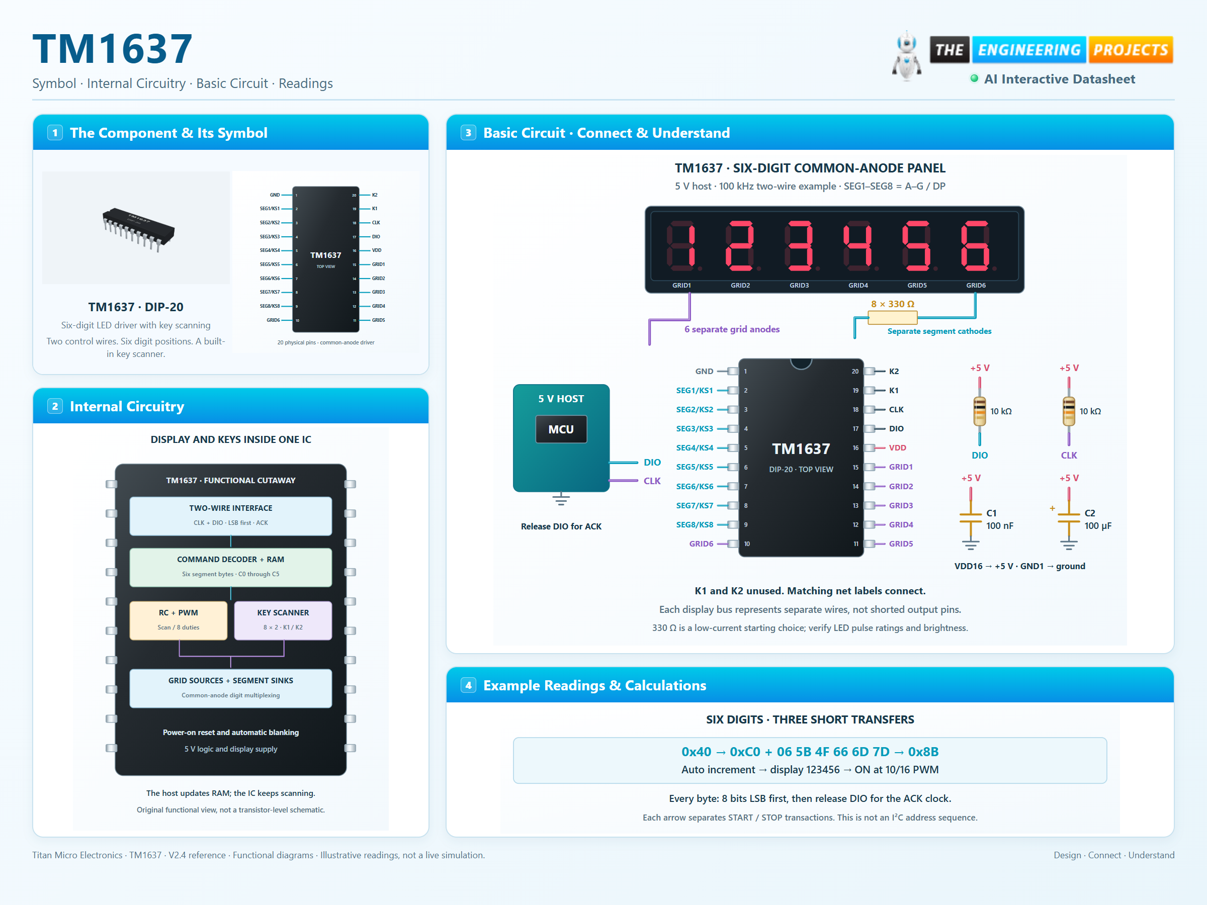
How it works
3 stages · Explore one step at a time
Connect a common-anode display
GRID1–GRID6 feed the digit anodes; SEG1–SEG8 sink the corresponding segment cathodes.
Write segment patterns
Choose sequential or fixed-address writes and acknowledge each byte.
Set brightness and read keys
Display control selects one of eight PWM duties; 0x42 requests key data.
Step 1 of 3
TM1637 in a circuit
5 V host, bidirectional data, pull-ups and local bypassing.
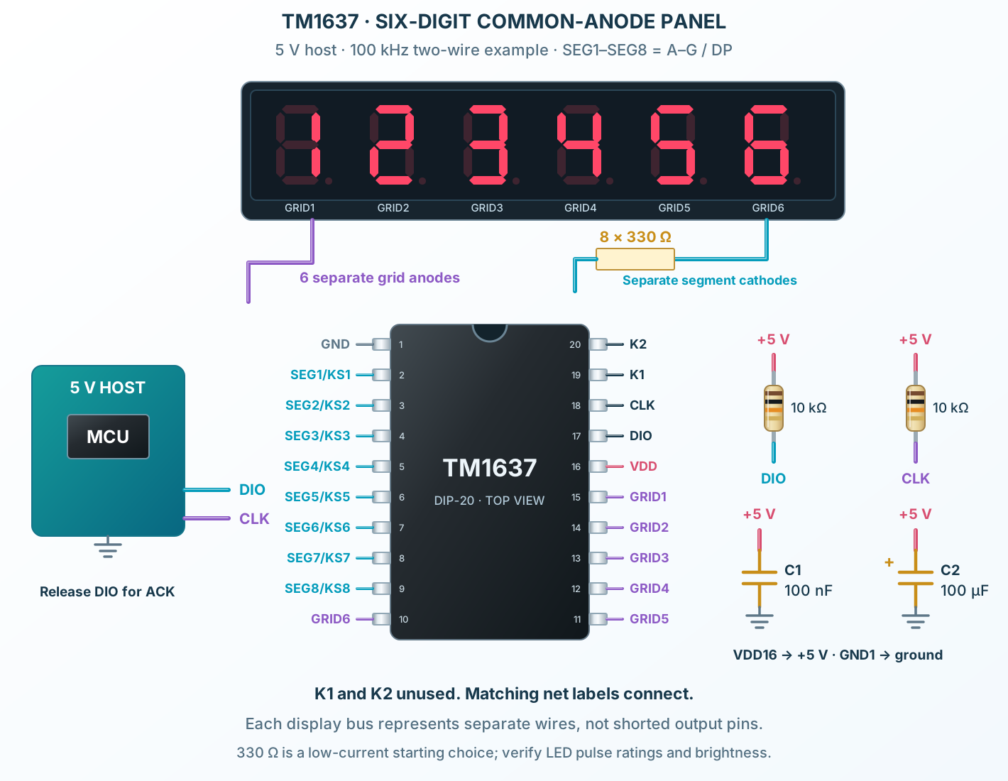
Connect it, step by step
Follow the component values and pin connections
Power and bypass
Use regulated 5 V, common ground, 100 nF and 100 µF near the IC.
Release DIO for ACK
Pull CLK and DIO up through 10 kΩ and use a compatible host.
Write and enable
Write the six display bytes with 0x40 / 0xC0, then enable with 0x8B. K1/K2 are unused in this example.
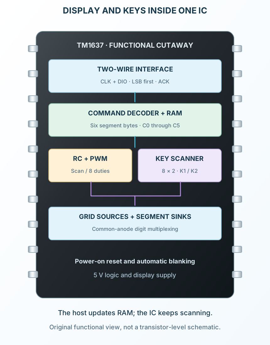
Inside TM1637
Compact functional view of serial, display and key-scan blocks.
Explore the circuit
Select a stage to see its role and connections
Receive and acknowledge
The two-wire front end recognizes START, bytes, ACK and STOP.
Store display bytes
Six RAM addresses retain raw segment patterns.
Scan LEDs and keys
Grid timing, segment sinks and the key returns work from the internal oscillator.
Selected packageDIP-20TM1637
Physical connections20 pinsPackage-specific numbering
Reference collection7 tables47 parameters & pin functions
Pin reference
Signal names, electrical functions and connection guidance
Physical pin numbers20 pins
Scroll within the table to see all columns and rows.
| Pin | Signal | Type | Function & connection |
|---|---|---|---|
| GND | Ground | Supply and segment-current return.Connection guidanceConnect to the common ground and the bypass capacitors. | |
| SEG1 / KS1 | Open-drain sink / scan | Sinks current from segment 1; also provides key-scan timing.Connection guidanceConnect to the shared cathodes of segment A across the display. A set display bit enables the corresponding sink during the selected grid slot. | |
| SEG2 / KS2 | Open-drain sink / scan | Sinks current from segment 2; also provides key-scan timing.Connection guidanceConnect to the shared cathodes of segment B across the display. A set display bit enables the corresponding sink during the selected grid slot. | |
| SEG3 / KS3 | Open-drain sink / scan | Sinks current from segment 3; also provides key-scan timing.Connection guidanceConnect to the shared cathodes of segment C across the display. A set display bit enables the corresponding sink during the selected grid slot. | |
| SEG4 / KS4 | Open-drain sink / scan | Sinks current from segment 4; also provides key-scan timing.Connection guidanceConnect to the shared cathodes of segment D across the display. A set display bit enables the corresponding sink during the selected grid slot. | |
| SEG5 / KS5 | Open-drain sink / scan | Sinks current from segment 5; also provides key-scan timing.Connection guidanceConnect to the shared cathodes of segment E across the display. A set display bit enables the corresponding sink during the selected grid slot. | |
| SEG6 / KS6 | Open-drain sink / scan | Sinks current from segment 6; also provides key-scan timing.Connection guidanceConnect to the shared cathodes of segment F across the display. A set display bit enables the corresponding sink during the selected grid slot. | |
| SEG7 / KS7 | Open-drain sink / scan | Sinks current from segment 7; also provides key-scan timing.Connection guidanceConnect to the shared cathodes of segment G across the display. A set display bit enables the corresponding sink during the selected grid slot. | |
| SEG8 / KS8 | Open-drain sink / scan | Sinks current from segment 8; also provides key-scan timing.Connection guidanceConnect to the shared cathodes of segment DP across the display. A set display bit enables the corresponding sink during the selected grid slot. | |
| GRID6 | High-side source | Drives the common anode of digit 6.Connection guidanceConnect to the common anode of display digit 6. Use common-anode LEDs; these outputs are not logic-level GPIO. | |
| GRID5 | High-side source | Drives the common anode of digit 5.Connection guidanceConnect to the common anode of display digit 5. Use common-anode LEDs; these outputs are not logic-level GPIO. | |
| GRID4 | High-side source | Drives the common anode of digit 4.Connection guidanceConnect to the common anode of display digit 4. Use common-anode LEDs; these outputs are not logic-level GPIO. | |
| GRID3 | High-side source | Drives the common anode of digit 3.Connection guidanceConnect to the common anode of display digit 3. Use common-anode LEDs; these outputs are not logic-level GPIO. | |
| GRID2 | High-side source | Drives the common anode of digit 2.Connection guidanceConnect to the common anode of display digit 2. Use common-anode LEDs; these outputs are not logic-level GPIO. | |
| GRID1 | High-side source | Drives the common anode of digit 1.Connection guidanceConnect to the common anode of display digit 1. Use common-anode LEDs; these outputs are not logic-level GPIO. | |
| VDD | Supply | Powers the logic and display drivers.Connection guidanceThe example uses a regulated 5 V rail with 100 nF and 100 µF bypass near the IC. Electrical and timing characteristics are specified at 4.5–5.5 V; follow the purchased part revision. | |
| DIO | Bidirectional data | Transfers command, display and key bytes; the IC pulls this line LOW for acknowledgement.Connection guidanceUse a 10 kΩ pull-up to 5 V and an open-drain or releasable host pin. Release the line for the ninth ACK clock and when reading keys; never contend with the IC output. | |
| CLK | Clock input | Clocks data on rising edges.Connection guidanceUse a 10 kΩ pull-up to 5 V; the example host clocks at 100 kHz. This two-wire protocol is not I²C: no slave address, and bytes are sent least-significant bit first. | |
| K1 | Key input | First row input for the 8 × 2 key matrix.Connection guidanceOptional keys connect to the SEG/KS scan lines as shown in the manufacturer circuit. Internal nominal 10 kΩ pull-down; leave unused key inputs unconnected. | |
| K2 | Key input | Second row input for the 8 × 2 key matrix.Connection guidanceRead with command 0x42; one key code is returned. Combined key presses are not supported; idle key data is 0xFF. |
No pins match these filters. Try another signal name or reset the filters.
Supply and electrical conditions
Distinguish operating conditions from absolute limits
Manufacturer-referenced values8 parameters
Scroll within the table to see all columns and rows.
| Parameter | Value | Conditions / notes |
|---|---|---|
| Nominal application supply | 5 V | V2.4 reference circuit |
| Electrical/timing test supply | 4.5–5.5 V | Published characteristics use this range |
| Input HIGH / LOW | ≥0.7 × VDD / ≤0.3 × VDD | At 5 V: ≥3.5 V HIGH, ≤1.5 V LOW |
| Operating temperature | −40 to +85°C | Board and LED heating must remain within limits |
| No-load current, display OFF | 5 mA maximum | Not total LED supply current |
| Internal oscillator | 450 kHz typical | RC oscillator; display scan is automatic |
| Bypass example | 100 nF ceramic + 100 µF bulk | Place close to VDD16 / GND1 |
| Absolute limits | 7 V supply; 400 mW dissipation | Damage limits, not recommended operating settings |
No specifications match. Try a parameter name or a unit.
Use a compatible host or proper level translation; a 3.3 V HIGH is not guaranteed at a 5 V supply.
Display and key commands
Each command byte is sent LSB first
Manufacturer-referenced values8 parameters
Scroll within the table to see all columns and rows.
| Parameter | Value | Conditions / notes |
|---|---|---|
| 0x40 | Write display, auto increment | Normal mode; addresses advance through six bytes |
| 0x44 | Write display, fixed address | Send the chosen address and one byte |
| 0x42 | Read key-scan code | Release DIO for IC-to-host transfer |
| 0xC0–0xC5 | Set display address | GRID1 through GRID6 respectively |
| 0xC6 and higher | Outside display RAM | Data ignored until a valid address is selected |
| 0x80 | Display OFF | Output blanking command |
| 0x88–0x8F | Display ON + brightness | Low three bits select the PWM setting |
| Test mode bit | Keep cleared | Reserved for manufacturer testing |
No specifications match. Try a parameter name or a unit.
There is no I²C slave address or decimal-to-segment decoder.
Segment bytes and example digits
Example wiring: SEG1…SEG8 = A, B, C, D, E, F, G, DP
Manufacturer-referenced values7 parameters
Scroll within the table to see all columns and rows.
| Parameter | Value | Conditions / notes |
|---|---|---|
| Byte D0…D7 | SEG1…SEG8 | A set bit enables its segment |
| Blank / dash | 0x00 / 0x40 | Dash uses only segment G |
| Digits 0, 1, 2, 3 | 0x3F, 0x06, 0x5B, 0x4F | For the stated segment wiring |
| Digits 4, 5, 6, 7 | 0x66, 0x6D, 0x7D, 0x07 | No automatic font decoding |
| Digits 8, 9 | 0x7F, 0x6F | Decimal point remains off |
| Decimal point | OR the byte with 0x80 | Some modules wire this output to a colon instead |
| Six-digit example 123456 | 06 5B 4F 66 6D 7D | Send after 0xC0 with auto increment enabled |
No specifications match. Try a parameter name or a unit.
A breakout module can have a different digit or colon map; check its wiring.
Eight PWM brightness settings
Duty applies during the selected digit slot
Manufacturer-referenced values8 parameters
Scroll within the table to see all columns and rows.
| Parameter | Value | Conditions / notes |
|---|---|---|
| 0x88 / level 0 | 1/16 | Display ON; minimum PWM |
| 0x89 / level 1 | 2/16 | |
| 0x8A / level 2 | 4/16 | |
| 0x8B / level 3 | 10/16 | The step from level 2 is intentionally large |
| 0x8C / level 4 | 11/16 | |
| 0x8D / level 5 | 12/16 | |
| 0x8E / level 6 | 13/16 | |
| 0x8F / level 7 | 14/16 | Maximum PWM setting |
No specifications match. Try a parameter name or a unit.
PWM duty is not the complete per-LED average duty: digit multiplexing also applies.
Two-wire timing
Use the conservative 100 kHz example for both writing and key reads
Manufacturer-referenced values8 parameters
Scroll within the table to see all columns and rows.
| Parameter | Value | Conditions / notes |
|---|---|---|
| START / STOP | DIO falls / rises while CLK HIGH | Keep DIO stable during ordinary HIGH clock periods |
| Bit order | Least-significant bit first | Different from many SPI devices |
| Acknowledge | Ninth clock; DIO pulled LOW | Host releases DIO after bit 7 |
| Write clock upper specification | 500 kHz at 50% duty | Electrical table maximum, subject to timing limits |
| Key-read clock | Below 250 kHz | Additional instruction in the key-read section |
| Clock pulse width | At least 400 ns | Observe all other timing constraints too |
| Data setup / hold | At least 100 ns / 100 ns | Relative to CLK |
| Waiting time | At least 1 µs | CLK rising to falling in the timing table |
No specifications match. Try a parameter name or a unit.
The 100 kHz demonstration provides margin for pull-ups, wiring capacitance and host timing.
Key scan and output loading
Optional 8 × 2 matrix shares the segment scan lines
Manufacturer-referenced values8 parameters
Scroll within the table to see all columns and rows.
| Parameter | Value | Conditions / notes |
|---|---|---|
| K1 / K2 contacts | Pins 19 / 20 | Two key-return inputs |
| Idle key code | 0xFF | No key reported |
| Simultaneous keys | Not supported | Do not assume rollover or independent key bits |
| Key input bias | 10 kΩ nominal internal pull-down | Unused K1/K2 can remain unconnected |
| Segment sink capability | 20 / 30 / 50 mA min / typ / max | At VO=0.3 V in the electrical table |
| Grid source capability | 80 / 120 / 180 mA min / typ / max | At VO=VDD−2 V |
| Current interpretation | These are output-characteristic test values | Not a guaranteed constant-current setting or a free current budget |
| Display loading | Check LED pulse limits and IC dissipation | Use segment resistors when required by the selected display/current design |
No specifications match. Try a parameter name or a unit.
Unlike MAX7219, TM1637 has no external RSET pin; do not copy the MAX7219 current-setting circuit.
No matching rowsTry a pin name, parameter, unit or test condition, or reset the filters.
Clocks and counters
Drive common-anode numeric panels using a small host pin budget.
Manufacturer application guideSmall appliance panels
Combine six digit positions with an optional key matrix.
Manufacturer application guideEducational displays
Inspect segment bytes, ACK timing and non-linear brightness settings.
Manufacturer application guideTake it into ProTech
Find TM1637 in the Components Library to place its schematic symbol and connect its pins.
Reference page · circuit simulation model not yet availableOpen ProTech