Real View
Start a pulse. Measure current. End it at the threshold.
UC3842A is a current-mode PWM controller with an oscillator, voltage-error amplifier, current comparator, latch and gate driver. It begins a switching pulse with the oscillator and ends it when the sensed current reaches the threshold requested by the feedback loop. This variant uses a nominal 16 V startup threshold and a 10 V turn-off threshold. It can operate near full duty cycle; it must not be confused with the lower-startup UC3843A or the half-duty UC3844A and UC3845A variants. The example uses an 18 V bench supply, an RC oscillator and an adjustable low-voltage signal at ISENSE. It demonstrates pulse truncation on a scope without a power MOSFET, transformer or mains connection. The selected eight-pin packages keep the same electrical pin numbers.
Select a pin to explore its connection
Click a lead or use the arrow keys. Top view
Controls the current comparator threshold and accepts the loop-compensation network.
Leave externally open in the fixed-demand bench circuit.
Do not force the node against its amplifier drive.
Inverting error-amplifier input, compared with an internal nominal 2.5 V reference.
Ground in this open-loop scope demonstration to request the maximum current threshold.
A real regulated converter needs feedback and compensation; this example has no power stage.
Ends an output pulse when the sense voltage exceeds the COMP-derived threshold; the maximum threshold is approximately 1 V.
Feed a 0–1.25 V control through 1 kΩ, with 1 nF to GND at the input.
DC above the threshold can leave very short pulses because turn-off has propagation delay.
Connects both the charging resistor and timing capacitor.
Use RT = 10 kΩ from VREF8 to this pin and CT = 3.3 nF from this pin to GND.
RT returns to VREF, not to ground.
Control and driver return in the selected eight-pin packages.
Join timing, bypass, control and scope grounds locally.
Pulsed output intended to drive an external power switch through a suitable gate resistor.
Connect a high-impedance scope and a 10 kΩ load to GND in this demonstration.
The 1 A headline is peak driver capability, not a continuous load supply.
Undervoltage lockout keeps OUTPUT low until startup voltage is reached.
Use regulated +18 V with 10 µF and 100 nF local bypass.
UC3842A starts around 16 V; a 12 V supply may never start it.
Bias and oscillator supply available after startup.
Bypass with 1 µF; feed RT and the low-current sense-control network.
Keep normal external reference load at or below 10 mA.
COMP sets the sense threshold below an internal clamp. The output latch prevents a second full pulse until the next clock cycle.
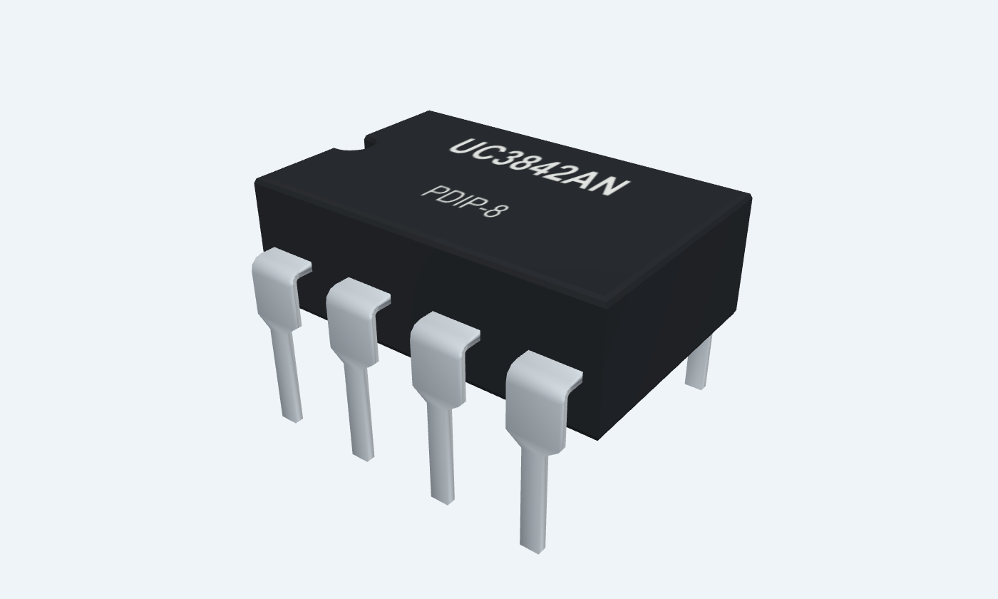
UC3842AN · PDIP-8
| Property | Details |
|---|---|
| Manufacturer | Texas Instruments |
| Part number | UC3842AN |
| Package | PDIP-8 |
| Connections | 8 pins |
| Mounting | Through-hole |
| Lead pitch | 2.54 mm |
| Package code | PDIP-8 |
| Thermal reference | See operating and package limits |
UC3842A variant only
Scroll sideways to see all columns.
| Parameter | Value | Conditions / notes |
|---|---|---|
| Startup threshold | 14.5–17.5 V; 16 V typical | VCC rising |
| Turn-off threshold | 8.5–11.5 V; 10 V typical | VCC falling after turn-on |
| Example supply | 18 V regulated | Allows margin above the maximum startup threshold |
| Startup current | 0.3 mA typical; 0.5 mA maximum | Specified test conditions |
| Operating supply current | 11 mA typical; 17 mA maximum | FB and ISENSE grounded; unloaded test conditions |
| Ambient temperature | 0 to +70°C | Selected UC3842A grade |
No specifications match. Try a parameter name or a unit.
The shared family operating table does not override the UC3842A startup threshold.
UC384xA specifications
Scroll sideways to see all columns.
| Parameter | Value | Conditions / notes |
|---|---|---|
| Initial VREF | 4.9–5.1 V; 5 V typical | TJ = 25°C, IO = 1 mA |
| Total VREF variation | 4.82–5.18 V | Specified line, load and temperature |
| Normal VREF load | 10 mA maximum | Reference supplies timing and control networks |
| VREF bypass | 1 µF | Close to VREF8 and GND5 |
| FB regulation reference | 2.42–2.58 V; 2.5 V typical | VCOMP = 2.5 V |
| Amplifier unity bandwidth | 1 MHz typical; 0.7 MHz minimum | Manufacturer test conditions |
| Amplifier output | COMP1 | Compensation and current-demand control |
No specifications match. Try a parameter name or a unit.
VREF is not a motor or general power-supply output.
Eight-pin RT/CT4
Scroll sideways to see all columns.
| Parameter | Value | Conditions / notes |
|---|---|---|
| RT connection | VREF8 to RT/CT4 | Recommended resistor range 5–100 kΩ |
| CT connection | RT/CT4 to GND5 | Recommended capacitance 470 pF–4.7 nF |
| Example network | 10 kΩ and 3.3 nF | Matches the electrical-characteristic timing setup |
| Initial frequency | 47–57 kHz; 52 kHz typical | TJ = 25°C and stated datasheet conditions |
| Typical period | About 19.2 µs | 1 / 52 kHz |
| Maximum duty capability | 92% minimum; 96% typical | UC3842A test conditions |
| Other family members | UC3844A / UC3845A limit duty to about half | Do not mix their timing behavior with this page |
No specifications match. Try a parameter name or a unit.
Frequency and maximum duty are affected by discharge current and the RC network.
Voltage determines external peak current
Scroll sideways to see all columns.
| Parameter | Value | Conditions / notes |
|---|---|---|
| Maximum sense input | 0.9–1.1 V; 1 V typical | VCOMP = 5 V; specified test |
| Sense control gain | 2.85–3.15 V/V; 3 typical | Specified current-sense transfer |
| Comparator delay | 150 ns typical; 300 ns maximum | ISENSE transition from 0 to 2 V |
| Shunt relationship | IPK ≈ VTRIP / RSENSE | Ignores propagation overshoot and filtering |
| Illustrative 0.5 Ω shunt | 1 V / 0.5 Ω = 2 A | Calculation only; no shunt or power stage in the bench demo |
| DC sense above threshold | Pulses are cut short | Propagation delay can leave narrow pulses |
| Duty above 50% | Slope compensation may be needed | Current-mode subharmonic behavior must be checked |
No specifications match. Try a parameter name or a unit.
Actual power-stage peak current also depends on delay, noise filtering, tolerances and inductor current slope.
Observe current-comparator action
Scroll sideways to see all columns.
| Parameter | Value | Conditions / notes |
|---|---|---|
| VCC7 / GND5 | 18 V / common return | 10 µF and 100 nF local supply bypass |
| VREF8 | 1 µF bypass | Feeds RT and the sense-control divider |
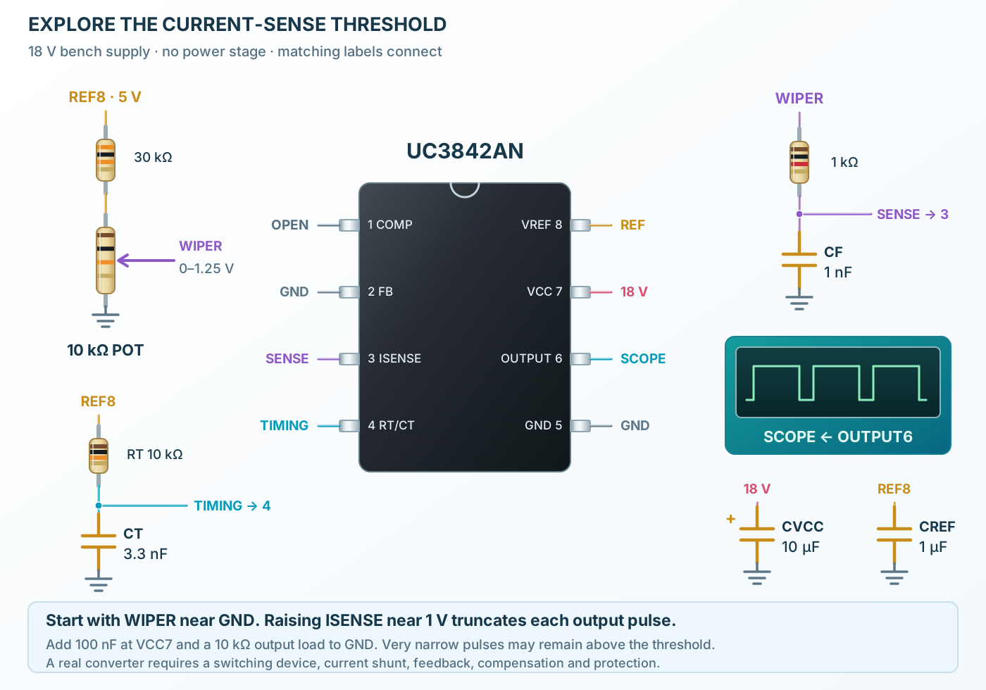
| RT / CT | 10 kΩ from REF to pin 4; 3.3 nF from pin 4 to GND | Keep timing traces short |
| FB2 / COMP1 | GND / no external connection | Maximum current demand in this demonstration |
| Sense control | 30 kΩ in series with a 10 kΩ pot across REF/GND | Pot wiper gives approximately 0–1.25 V |
| ISENSE3 filter | Wiper through 1 kΩ; 1 nF from pin 3 to GND | Reduces wiper noise; not a power-stage filter design |
| OUTPUT6 | High-impedance scope plus 10 kΩ to GND | No transformer or switching MOSFET |
| Control action | Raise sense voltage from zero | Observe pulse truncation near the comparator threshold |
No specifications match. Try a parameter name or a unit.
All grounds share one return. The output can reach near VCC; use a properly rated probe.
Totem-pole gate drive
Scroll sideways to see all columns.
| Parameter | Value | Conditions / notes |
|---|---|---|
| Peak output capability | Up to ±1 A | Peak gate drive; observe thermal and pulse limits |
| LOW at 20 mA sink | 0.1 V typical; 0.4 V maximum | Specified VCC = 15 V test |
| HIGH at 20 mA source | 13.5 V typical; 13 V minimum | Specified VCC = 15 V test |
| External MOSFET connection | Use a suitable gate resistor | Limits peak gate charging current |
| Supply bypass sizing | VCC capacitance at least 10× VREF bypass | Also account for power-switch gate capacitance |
| Ground arrangement | Short local timing and sense returns | Keep gate-current loops away from analog inputs |
No specifications match. Try a parameter name or a unit.
The eight-pin version shares power and signal ground internally; larger packages have additional pins.
UC3842AN · PDIP-8
Scroll sideways to see all columns.
| Parameter | Value | Conditions / notes |
|---|---|---|
| PDIP reference | UC3842AN · 8 pins | TI P; current appendix marks NRND |
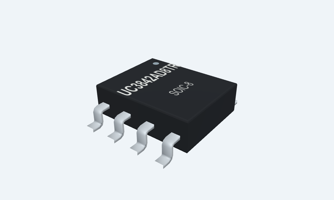
| SMD reference | UC3842AD8TR · 8 pins | TI D8; active orderable in reviewed appendix |
| Different SMD ordering | UC3842AD · 14 pins | Different pin map; not represented by this eight-pin preview |
| VCC absolute maximum | 30 V from a low-impedance source | Stress limit; not a recommended operating target |
| Analog-input absolute range | −0.3 to +6.3 V | Recommended analog limits are tighter |
| Storage temperature | −65 to +150°C | Unpowered |
| Output capacitive energy | 5 µJ absolute maximum | Check driver dissipation and repetition |
No specifications match. Try a parameter name or a unit.
Use exact suffixes and manufacturer drawings when selecting a package.
Select a pin for its function, connection guidance and electrical notes.
Follow the labeled connections and functional stages
3 stages · Explore one step at a time
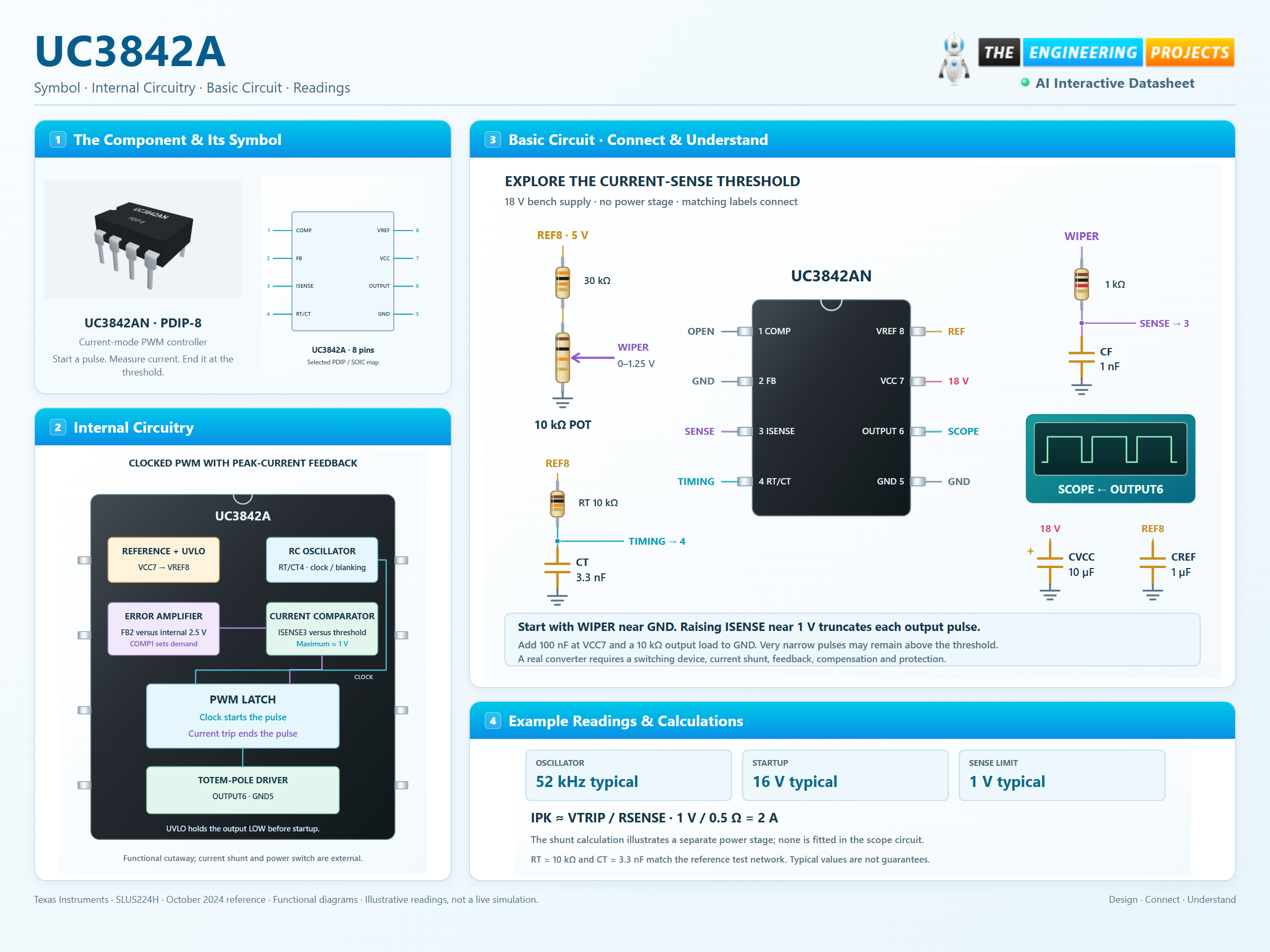
VCC must first reach the start threshold. After startup, hysteresis permits operation at a lower voltage.
The error amplifier compares FB with 2.5 V. COMP programs the current-comparator trip point, up to the internal limit.
A sufficiently high ISENSE signal resets the PWM latch. Oscillator blanking also limits maximum duty.
An RC oscillator, a low-voltage control and a scope.
Follow the component values and pin connections
An 18 V supply exceeds the specified maximum start threshold. A 12 V supply is not sufficient for guaranteed cold startup.
RT connects to VREF and CT connects to ground, meeting at pin 4.
Increase the pot wiper from zero toward 1.25 V and observe shorter pulses. Very narrow pulses may remain above the threshold.
Reference, current comparator and a clocked PWM latch.
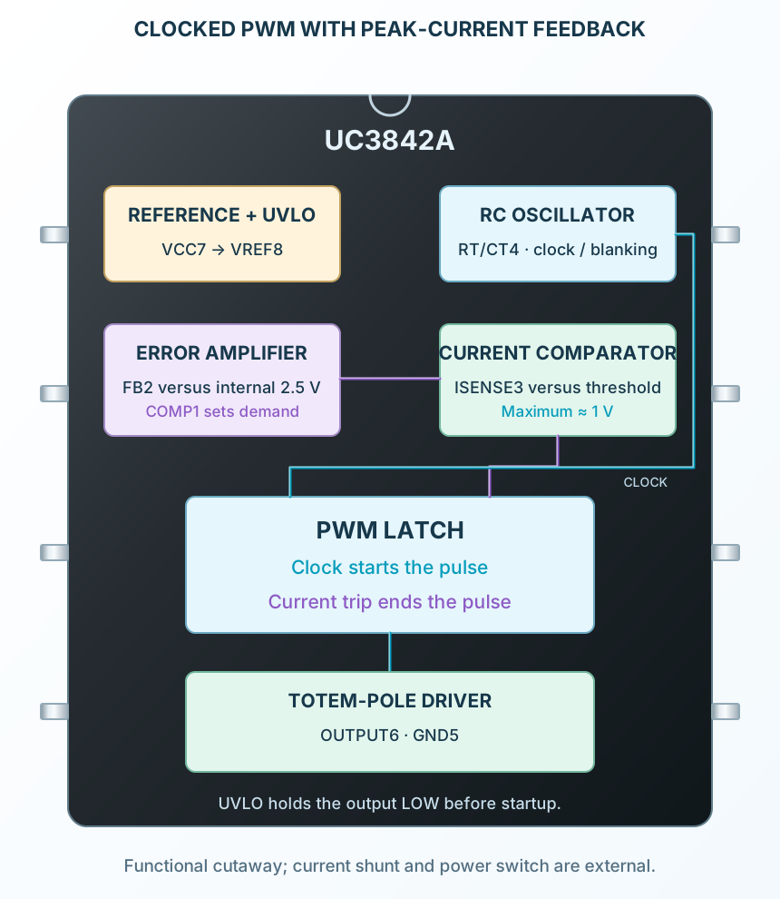
Select a stage to see its role and connections
UVLO controls startup. VREF supplies timing and the feedback reference.
COMP sets a threshold for ISENSE, bounded by the internal clamp.
A current trip ends the pulse; the next oscillator cycle allows a new one.
Signal names, electrical functions and connection guidance
Scroll within the table to see all columns and rows.
| Pin | Signal | Type | Function & connection |
|---|---|---|---|
| COMP | Error-amplifier output | Controls the current comparator threshold and accepts the loop-compensation network.Connection guidanceLeave externally open in the fixed-demand bench circuit. Do not force the node against its amplifier drive. | |
| FB | Voltage feedback | Inverting error-amplifier input, compared with an internal nominal 2.5 V reference.Connection guidanceGround in this open-loop scope demonstration to request the maximum current threshold. A real regulated converter needs feedback and compensation; this example has no power stage. | |
| ISENSE | Current-sense input | Ends an output pulse when the sense voltage exceeds the COMP-derived threshold; the maximum threshold is approximately 1 V.Connection guidanceFeed a 0–1.25 V control through 1 kΩ, with 1 nF to GND at the input. DC above the threshold can leave very short pulses because turn-off has propagation delay. | |
| RT/CT | Oscillator timing node | Connects both the charging resistor and timing capacitor.Connection guidanceUse RT = 10 kΩ from VREF8 to this pin and CT = 3.3 nF from this pin to GND. RT returns to VREF, not to ground. | |
| GND | Common return | Control and driver return in the selected eight-pin packages.Connection guidanceJoin timing, bypass, control and scope grounds locally. | |
| OUTPUT | Totem-pole gate driver | Pulsed output intended to drive an external power switch through a suitable gate resistor.Connection guidanceConnect a high-impedance scope and a 10 kΩ load to GND in this demonstration. The 1 A headline is peak driver capability, not a continuous load supply. | |
| VCC | Controller and driver supply | Undervoltage lockout keeps OUTPUT low until startup voltage is reached.Connection guidanceUse regulated +18 V with 10 µF and 100 nF local bypass. UC3842A starts around 16 V; a 12 V supply may never start it. | |
| VREF | 5 V reference | Bias and oscillator supply available after startup.Connection guidanceBypass with 1 µF; feed RT and the low-current sense-control network. Keep normal external reference load at or below 10 mA. |
No pins match these filters. Try another signal name or reset the filters.
UC3842A variant only
Scroll within the table to see all columns and rows.
| Parameter | Value | Conditions / notes |
|---|---|---|
| Startup threshold | 14.5–17.5 V; 16 V typical | VCC rising |
| Turn-off threshold | 8.5–11.5 V; 10 V typical | VCC falling after turn-on |
| Example supply | 18 V regulated | Allows margin above the maximum startup threshold |
| Startup current | 0.3 mA typical; 0.5 mA maximum | Specified test conditions |
| Operating supply current | 11 mA typical; 17 mA maximum | FB and ISENSE grounded; unloaded test conditions |
| Ambient temperature | 0 to +70°C | Selected UC3842A grade |
No specifications match. Try a parameter name or a unit.
The shared family operating table does not override the UC3842A startup threshold.
UC384xA specifications
Scroll within the table to see all columns and rows.
| Parameter | Value | Conditions / notes |
|---|---|---|
| Initial VREF | 4.9–5.1 V; 5 V typical | TJ = 25°C, IO = 1 mA |
| Total VREF variation | 4.82–5.18 V | Specified line, load and temperature |
| Normal VREF load | 10 mA maximum | Reference supplies timing and control networks |
| VREF bypass | 1 µF | Close to VREF8 and GND5 |
| FB regulation reference | 2.42–2.58 V; 2.5 V typical | VCOMP = 2.5 V |
| Amplifier unity bandwidth | 1 MHz typical; 0.7 MHz minimum | Manufacturer test conditions |
| Amplifier output | COMP1 | Compensation and current-demand control |
No specifications match. Try a parameter name or a unit.
VREF is not a motor or general power-supply output.
Eight-pin RT/CT4
Scroll within the table to see all columns and rows.
| Parameter | Value | Conditions / notes |
|---|---|---|
| RT connection | VREF8 to RT/CT4 | Recommended resistor range 5–100 kΩ |
| CT connection | RT/CT4 to GND5 | Recommended capacitance 470 pF–4.7 nF |
| Example network | 10 kΩ and 3.3 nF | Matches the electrical-characteristic timing setup |
| Initial frequency | 47–57 kHz; 52 kHz typical | TJ = 25°C and stated datasheet conditions |
| Typical period | About 19.2 µs | 1 / 52 kHz |
| Maximum duty capability | 92% minimum; 96% typical | UC3842A test conditions |
| Other family members | UC3844A / UC3845A limit duty to about half | Do not mix their timing behavior with this page |
No specifications match. Try a parameter name or a unit.
Frequency and maximum duty are affected by discharge current and the RC network.
Voltage determines external peak current
Scroll within the table to see all columns and rows.
| Parameter | Value | Conditions / notes |
|---|---|---|
| Maximum sense input | 0.9–1.1 V; 1 V typical | VCOMP = 5 V; specified test |
| Sense control gain | 2.85–3.15 V/V; 3 typical | Specified current-sense transfer |
| Comparator delay | 150 ns typical; 300 ns maximum | ISENSE transition from 0 to 2 V |
| Shunt relationship | IPK ≈ VTRIP / RSENSE | Ignores propagation overshoot and filtering |
| Illustrative 0.5 Ω shunt | 1 V / 0.5 Ω = 2 A | Calculation only; no shunt or power stage in the bench demo |
| DC sense above threshold | Pulses are cut short | Propagation delay can leave narrow pulses |
| Duty above 50% | Slope compensation may be needed | Current-mode subharmonic behavior must be checked |
No specifications match. Try a parameter name or a unit.
Actual power-stage peak current also depends on delay, noise filtering, tolerances and inductor current slope.
Observe current-comparator action
Scroll within the table to see all columns and rows.
| Parameter | Value | Conditions / notes |
|---|---|---|
| VCC7 / GND5 | 18 V / common return | 10 µF and 100 nF local supply bypass |
| VREF8 | 1 µF bypass | Feeds RT and the sense-control divider |
| RT / CT | 10 kΩ from REF to pin 4; 3.3 nF from pin 4 to GND | Keep timing traces short |
| FB2 / COMP1 | GND / no external connection | Maximum current demand in this demonstration |
| Sense control | 30 kΩ in series with a 10 kΩ pot across REF/GND | Pot wiper gives approximately 0–1.25 V |
| ISENSE3 filter | Wiper through 1 kΩ; 1 nF from pin 3 to GND | Reduces wiper noise; not a power-stage filter design |
| OUTPUT6 | High-impedance scope plus 10 kΩ to GND | No transformer or switching MOSFET |
| Control action | Raise sense voltage from zero | Observe pulse truncation near the comparator threshold |
No specifications match. Try a parameter name or a unit.
All grounds share one return. The output can reach near VCC; use a properly rated probe.
Totem-pole gate drive
Scroll within the table to see all columns and rows.
| Parameter | Value | Conditions / notes |
|---|---|---|
| Peak output capability | Up to ±1 A | Peak gate drive; observe thermal and pulse limits |
| LOW at 20 mA sink | 0.1 V typical; 0.4 V maximum | Specified VCC = 15 V test |
| HIGH at 20 mA source | 13.5 V typical; 13 V minimum | Specified VCC = 15 V test |
| External MOSFET connection | Use a suitable gate resistor | Limits peak gate charging current |
| Supply bypass sizing | VCC capacitance at least 10× VREF bypass | Also account for power-switch gate capacitance |
| Ground arrangement | Short local timing and sense returns | Keep gate-current loops away from analog inputs |
No specifications match. Try a parameter name or a unit.
The eight-pin version shares power and signal ground internally; larger packages have additional pins.
UC3842AN · PDIP-8
Scroll within the table to see all columns and rows.
| Parameter | Value | Conditions / notes |
|---|---|---|
| PDIP reference | UC3842AN · 8 pins | TI P; current appendix marks NRND |
| SMD reference | UC3842AD8TR · 8 pins | TI D8; active orderable in reviewed appendix |
| Different SMD ordering | UC3842AD · 14 pins | Different pin map; not represented by this eight-pin preview |
| VCC absolute maximum | 30 V from a low-impedance source | Stress limit; not a recommended operating target |
| Analog-input absolute range | −0.3 to +6.3 V | Recommended analog limits are tighter |
| Storage temperature | −65 to +150°C | Unpowered |
| Output capacitive energy | 5 µJ absolute maximum | Check driver dissipation and repetition |
No specifications match. Try a parameter name or a unit.
Use exact suffixes and manufacturer drawings when selecting a package.
No matching rowsTry a pin name, parameter, unit or test condition, or reset the filters.
Control a separately designed flyback, forward or other compatible power stage.
Manufacturer application guideUse an external sense network to limit peak switching current.
Manufacturer application guideInspect the oscillator and comparator response without connecting a power stage.
Manufacturer application guideFind UC3842A in the Components Library to place its schematic symbol and connect its pins.
Reference page · circuit simulation model not yet availableOpen ProTech