Real View
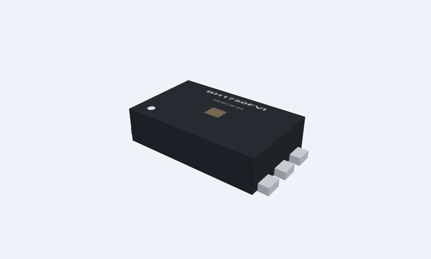
Turn ambient light into a readable lux value.
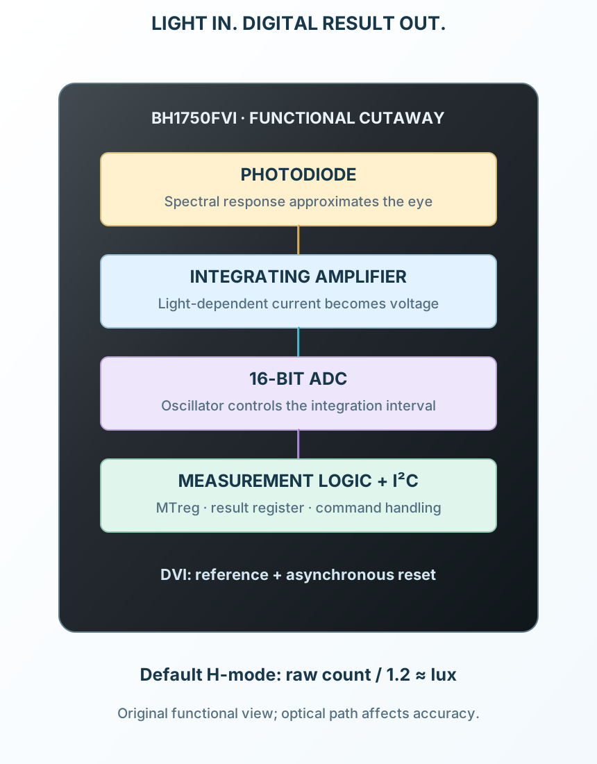
BH1750FVI is an ambient-light sensor with a photodiode, integrating amplifier, analog-to-digital converter and I²C interface. Its spectral response approximates human vision, making it useful for display brightness control and general illuminance measurements. The bare WSOF6I device has six terminals. Commands select continuous or one-time measurements at different resolutions. The two returned bytes form a 16-bit result; firmware applies the mode and measurement-time scaling to obtain lux. Optical windows, light spectrum and device tolerance still affect the result. The example uses 3.3 V, address 0x23 and continuous high-resolution mode. It explicitly controls the DVI reset/reference terminal during startup, then waits for the first conversion. A sample result of 600 counts corresponds to approximately 500 lux with the default measurement-time setting.
Click a lead or use the arrow keys. Top view · rotated clockwise
Analog sensor supply.
Use regulated 3.3 V with 100 nF to ground.
Recommended 2.4–3.6 V.
Selects seven-bit address 0x23 when low or 0x5C when high.
Use 100 kΩ to GND in the example.
ROHM recommends a resistor if the required DVI reset interval is not guaranteed; do not float.
Common return for power and I²C.
Join controller ground.
Receives commands and returns a 16-bit result.
Connect to controller SDA with 4.7 kΩ to the DVI reference rail.
Sets SDA/SCL input levels and resets the internal state when held low.
Hold below 0.4 V for more than 1 µs after VCC is present, then drive to 3.3 V.
The firmware example holds reset low for 1 ms and allows DVI to settle before I²C. Operating reference 1.65 V to VCC.
I²C clock input from the host.
Connect to controller SCL with 4.7 kΩ to DVI.
100 kHz in this example; 400 kHz maximum.
16-bit I²C ambient-light sensor
The measurement integrates incident light over a defined interval. Reading before completion can return an old value. High-resolution mode and mode 2 use different output scaling.
BH1750FVI
Key parameters and their test conditions
Follows the selected physical package
Select a pin to open its function, electrical notes and wiring guidance.
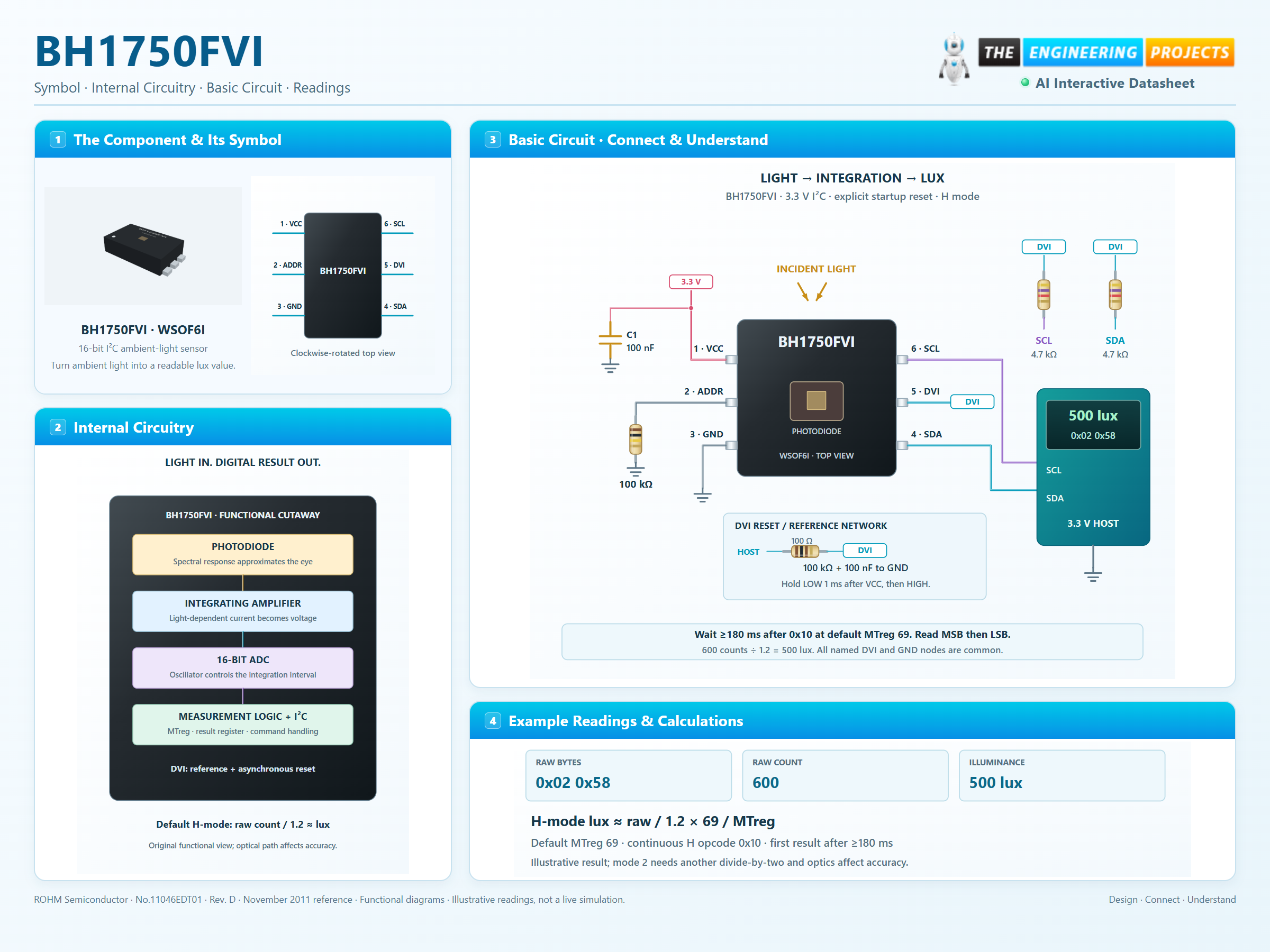
Hold DVI low after VCC rises, then enable its logic reference and allow it to settle.
Send 0x10 for continuous high-resolution mode at address 0x23. Wait at least 180 ms at the default MTreg.
Read high byte then low byte, NACK the final byte and stop. Combine them as an unsigned 16-bit count and apply the mode scaling.
At MTreg 69, high-resolution result 0x0258 is 600 counts; 600 / 1.2 = 500 lux. This is an illustrative calculation, not a live reading.
Select a pin to explore its function and connection.
| Pin | Signal | Type | Function |
|---|---|---|---|
| VCC | Supply | Analog sensor supply. | |
| ADDR | Address selection | Selects seven-bit address 0x23 when low or 0x5C when high. | |
| GND | Ground | Common return for power and I²C. | |
| SDA | Open-drain serial data | Receives commands and returns a 16-bit result. | |
| DVI | Logic reference and asynchronous reset | Sets SDA/SCL input levels and resets the internal state when held low. | |
| SCL | Serial clock | I²C clock input from the host. |
No pins match. Try a signal name or choose All pins.
Recommended limits and sequencing
| Parameter | Value | Conditions / notes |
|---|---|---|
| VCC | 2.4–3.6 V | 3.3 V example |
| DVI operating reference | 1.65 V to VCC | Also asynchronous reset |
| Reset low level | At most 0.4 V | Keep low for more than 1 µs after VCC is supplied |
| ADDR thresholds | Low ≤0.3 VCC; high ≥0.7 VCC | Address input is referenced to VCC |
| I²C bus maximum | 400 kHz | 100 kHz example |
| Operating temperature | −40 to +85°C | Separate from storage limits |
| Active current | 120 µA typical; 190 µA maximum | VCC=DVI=3 V, 25°C, 100 lux |
| Power-down current | 0.01 µA typical; 1 µA maximum | No incident light, stated conditions |
No specifications match. Try a parameter name or a unit.
An existing breakout may hide DVI or implement its reset with an RC network. Check its actual schematic.
Default measurement time register = 69
| Parameter | Value | Conditions / notes |
|---|---|---|
| Continuous H mode | 0x10 | 1 lux nominal resolution; 120 ms typical, 180 ms maximum |
| Continuous H mode 2 | 0x11 | 0.5 lux nominal resolution; 120 / 180 ms |
| Continuous L mode | 0x13 | 4 lux nominal resolution; 16 / 24 ms |
| One-time H mode | 0x20 | Returns to power down after acquisition |
| One-time H mode 2 | 0x21 | Higher resolution; returns to power down |
| One-time L mode | 0x23 | Shorter acquisition; returns to power down |
| Measurement-time adjustment | MTreg 31–254 | Default 69; integration time scales with MTreg |
No specifications match. Try a parameter name or a unit.
Resolution is not measurement accuracy. Do not apply H-mode scaling unchanged to mode 2.
Opcodes, not a conventional register-address map
| Parameter | Value | Conditions / notes |
|---|---|---|
| Power down | 0x00 | Stops measurement activity |
| Power on | 0x01 | Awaits a measurement command |
| Reset illuminance register | 0x07 | Use after power on; does not replace the DVI startup reset |
| MTreg high bits | 0x40 | (MTreg >> 5) | High three bits |
| MTreg low bits | 0x60 | (MTreg & 0x1F) | Low five bits |
| Read result | Two bytes, high byte first | Unsigned 16-bit value |
| ADDR low / high | 0x23 / 0x5C | Seven-bit address, not shifted read/write byte |
No specifications match. Try a parameter name or a unit.
A continuous mode repeats measurements; one-time mode needs another measurement command for a fresh result.
Scaling and uncertainty
| Parameter | Value | Conditions / notes |
|---|---|---|
| H-mode default | lux = raw / 1.2 | MTreg 69 |
| H-mode adjusted | lux = raw / 1.2 × 69 / MTreg | Integration-time scaling |
| H-mode 2 adjusted | lux = raw / 1.2 × 69 / MTreg / 2 | Additional factor of two |
| Example bytes | 0x02 and 0x58 | raw = 600 |
| Example illuminance | 500 lux | 600 / 1.2 at MTreg 69, H mode |
| Raw / lux ratio at 1000 lux | 0.96–1.44; typical 1.2 | Manufacturer white-LED test; approximately ±20% variation |
| Dark output | 0–3 counts | High-resolution mode, stated test conditions |
No specifications match. Try a parameter name or a unit.
Use actual optical-window transmission and calibration if a tighter system accuracy is required.
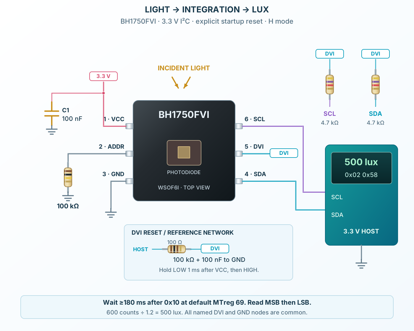
Explicit DVI control
| Parameter | Value | Conditions / notes |
|---|---|---|
| VCC1 | 3.3 V with 100 nF | Common ground at pin 3 |
| ADDR2 | 100 kΩ to GND | Selects 0x23 |
| DVI5 | Reset/reference control from 3.3 V host | 100 Ω series, 100 kΩ pulldown and 100 nF bypass in this example |
| Startup behavior | Hold host output low for 1 ms after valid VCC | Then drive high and allow settling before bus access |
| SDA4 and SCL6 | Controller I²C | 4.7 kΩ pull-ups to the settled DVI rail |
| Measurement | Continuous H, opcode 0x10 | Wait 180 ms or longer for first result |
| Display | 500 lux illustration | Derived from the example 600-count result |
No specifications match. Try a parameter name or a unit.
The host output must support the DVI reference and pull-up current. Do not let bus lines back-power an unpowered sensor.
Keep the sensing area exposed
| Parameter | Value | Conditions / notes |
|---|---|---|
| Peak spectral response | 560 nm typical | Approximates human-eye sensitivity |
| Light-source effects | Not identical for every spectrum | Check the reference response curves |
| Optical window | Keep at least the recommended clear region | Align with the photodiode area |
| Photodiode area | 0.25 × 0.30 mm | Located near the package center |
| Package | WSOF6I | 1.6 mm wide; 2.6 mm body; 3.0 mm overall; 0.75 mm maximum height |
| Terminal pitch | 0.50 mm | Three terminals at each end |
| Page orientation | Clockwise-rotated top view | 1/2/3 on left, 6/5/4 on right |
No specifications match. Try a parameter name or a unit.
The illustration shows a bare IC; breakout boards add their own electrical and optical details.
Avoid stale or incorrectly scaled readings
| Parameter | Value | Conditions / notes |
|---|---|---|
| Zero reading | Check power mode and reset | Also check optical obstruction |
| Old reading | Wait for the first conversion | Longer MTreg requires proportionally longer waits |
| Wrong address | Verify ADDR level | 0x23 low or 0x5C high |
| Result doubled | Check H-mode 2 scaling | Divide by two in addition to normal scaling |
| Window attenuation | Review MTreg and calibration | Do not infer transmission from appearance alone |
| Saturation | Reduce integration or choose the proper range | Check the final system under its brightest light |
No specifications match. Try a parameter name or a unit.
Mode, timing and optical path must be recorded alongside a lux value.
Measure room light for display or indicator control.
Manufacturer application guideRecord illuminance with timing and mode metadata.
Manufacturer application guideApply thresholds and hysteresis in host software.
Manufacturer application guideFind BH1750FVI in the Components Library to place its schematic symbol and connect its pins.
Working Arduino light-meter example available in ProTechOpen ProTech