Real View
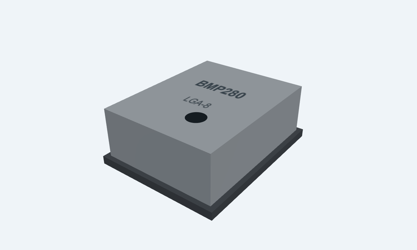
Measure air pressure. Compensate it with temperature.
BMP280 is a miniature digital sensor that measures barometric pressure and temperature. Its sensing elements and mixed-signal electronics share an eight-contact metal-lid LGA package. I²C and SPI provide the interface to a microcontroller; the IC itself has no display or regulator. The BMP280 has no humidity channel; a similar-looking BME280 is a different device. Raw conversion data must be compensated with calibration coefficients read from that individual sensor. Temperature compensation is performed first because the pressure calculation depends on its intermediate result. The example uses both supplies at 3.3 V, two local bypass capacitors and an I²C address of 0x76. Pin numbering runs clockwise in the top view, so pad 1 is at the upper right. The illustrated 25°C and 1000 hPa readings explain units; they are not measurements from a connected sensor.
Select a pin to explore its connection
Click a lead or use the arrow keys. Top view · clockwise numbering
First ground pad.
Join common ground; connect pad 7 too.
Selects the digital interface.
Tie directly to VDDIO for I²C; use controller chip-select for SPI.
For I²C it must already be high during power-on reset.
SPI input, shared three-wire data or I²C bidirectional data.
Connect to 3.3 V controller SDA and a 4.7 kΩ pull-up in the example.
SPI or I²C clock from the host.
Connect to controller SCL with a pull-up to VDDIO for I²C.
SPI serial output; the I²C address bit is sampled from its level.
Tie to GND for 0x76 or VDDIO for 0x77 in I²C.
Do not leave floating in I²C; unconnected in three-wire SPI.
Supplies the digital input/output domain.
Use 3.3 V and 100 nF to GND in this example.
Operating range 1.2–3.6 V; no 5 V bus pull-ups.
Second ground pad.
Join pad 1 and controller ground.
Powers the analog sensing and conversion circuitry.
Use 3.3 V and a separate 100 nF to GND.
Operating range 1.71–3.6 V.
Factory calibration belongs to each individual sensor. Read its coefficients, acquire a complete result and apply the manufacturer compensation in the correct order.
BMP280 · LGA-8
| Property | Details |
|---|---|
| Manufacturer | Bosch Sensortec |
| Part number | BMP280 |
| Package | LGA-8 |
| Connections | 8 pins |
| Mounting | SMD |
| Lead pitch | 0.65 mm |
| Package code | Metal-lid LGA |
| Thermal reference | Keep the vent open and isolate from board heat |
Recommended operating conditions
Scroll sideways to see all columns.
| Parameter | Value | Conditions / notes |
|---|---|---|
| VDD main supply | 1.71–3.6 V | 3.3 V in the example |
| VDDIO supply | 1.2–3.6 V | Sets the digital logic domain |
| Operating temperature | −40 to +85°C | Accuracy conditions are narrower |
| Pressure range | 300–1100 hPa | Absolute pressure |
| Humidity channel | Not present | Use BME280 if humidity is required |
| Startup before communication | 2 ms | Also wait until status.im_update clears |
| Sleep current | 0.1 µA typical | Sensor sleep; excludes external pull-ups and controller |
No specifications match. Try a parameter name or a unit.
Do not connect 5 V logic or pull-ups to the bare sensor.
Typical or stated accuracy conditions
Scroll sideways to see all columns.
| Parameter | Value | Conditions / notes |
|---|---|---|
| Pressure absolute accuracy | ±1 hPa typical | 950–1050 hPa, 0–40°C |
| Relative pressure accuracy | ±0.12 hPa | 700–900 hPa; 25°C |
| Temperature accuracy | ±0.5°C at 25°C | Internal die temperature; board heating affects ambient estimates |
| Pressure resolution | 0.16 Pa | Output resolution is not accuracy |
| Typical pressure noise | 1.3 Pa RMS | Highest resolution, full bandwidth |
| Filtered pressure noise | 0.2 Pa RMS typical | Highest oversampling and lowest bandwidth |
| Typical current at 1 Hz | 2.7 µA | Pressure and temperature |
No specifications match. Try a parameter name or a unit.
Resolution, noise, accuracy and conversion speed describe different limitations.
I²C and SPI configuration
Scroll sideways to see all columns.
| Parameter | Value | Conditions / notes |
|---|---|---|
| I²C chip selection | CSB2 tied to VDDIO | Required from power-on reset |
| I²C data / clock | SDI3 = SDA; SCK4 = SCL | Pull both bus lines to VDDIO |
| SDO5 low / high | 0x76 / 0x77 | Seven-bit addresses; do not float |
| I²C maximum clock | 3.4 MHz | Use the required high-speed protocol; example is 100 kHz |
| SPI maximum clock | 10 MHz | Observe setup, hold and output delay conditions |
| 4-wire SPI | CSB, SCK, SDI, SDO | Separate input and output data |
| 3-wire SPI | CSB, SCK and shared SDI | Set spi3w_en; SDO is unused |
No specifications match. Try a parameter name or a unit.
A module may contain its own pull-ups or regulator. Inspect its schematic separately.
Read whole measurement groups coherently
Scroll sideways to see all columns.
| Parameter | Value | Conditions / notes |
|---|---|---|
| 0xD0 chip ID | 0x58 | Distinguishes the selected part |
| 0xE0 reset | Write 0xB6 | Wait for startup / coefficient copy |
| 0xF3 status | Bit 3 measuring; bit 0 im_update | Do not read an old result as a just-triggered conversion |
| 0xF4 ctrl_meas | Temperature / pressure oversampling and mode | Example 0x25 = ×1 / ×1 / forced |
| 0xF5 config | Standby time, IIR and 3-wire selection | Configure in sleep; example filter off |
| 0xF7–0xFC | 20-bit pressure + 20-bit temperature | MSB, LSB and upper nibble of XLSB |
| Calibration | Temperature / pressure from 0x88 onward | Use each chip’s stored coefficients |
No specifications match. Try a parameter name or a unit.
Preserve signed coefficient types and packed fields; raw ADC data is not already °C, Pa or % RH.
Noise, response and current trade-offs
Scroll sideways to see all columns.
| Parameter | Value | Conditions / notes |
|---|---|---|
| Sleep | No measurements | Registers remain accessible |
| Forced | One measurement, then sleep | Host triggers the next result |
| Normal | Repeated measurement and standby | Choose standby for the required update rate |
| Oversampling | Skipped or ×1 / ×2 / ×4 / ×8 / ×16 | Each enabled channel configured separately |
| IIR | Off / 2 / 4 / 8 / 16 | Pressure and temperature; not humidity |
| Example conversion maximum | 6.425 ms | ×1 temperature and pressure; manufacturer timing formula |
| Fresh result check | Wait for the conversion to finish | Allow the full bounded duration or observe the busy-to-idle transition |
No specifications match. Try a parameter name or a unit.
Firmware must allow startup and bus time as well as the acquisition itself.
A bare-sensor connection
Scroll sideways to see all columns.
| Parameter | Value | Conditions / notes |
|---|---|---|
| VDD8 and VDDIO6 | 3.3 V | Separate 100 nF capacitors to common ground |
| GND1 and GND7 | Common ground | Connect both pads |
| CSB2 | 3.3 V | Select I²C from startup |
| SDO5 | GND | Address 0x76 |
| SDA3 and SCL4 | 3.3 V controller | 4.7 kΩ example pull-ups; verify bus rise time |
| Firmware order | Reset / wait / coefficients / configuration / convert / read | Temperature compensation before dependent channels |
| Display examples | 25.0°C · 1000.0 hPa | Illustrative engineering-unit values, not live readings |
No specifications match. Try a parameter name or a unit.
The display belongs to the host system, not the sensor package.
Clockwise top-view numbering
Scroll sideways to see all columns.
| Parameter | Value | Conditions / notes |
|---|---|---|
| Package body | 2 × 2.5 × 0.95 mm | Eight-contact metal-lid LGA |
| Pad pitch | 0.65 mm | Four contacts on each of two opposite sides |
| Top-view order | Right: 1,2,3,4 · left: 8,7,6,5 | Top to bottom; bottom view is mirrored |
| Vent opening | Keep clear | Avoid coating, adhesive or contamination in the port |
| Thermal placement | Away from hot ICs and airflow artifacts | Temperature senses package conditions |
| PCB lands | Authored 0.50 × 0.35 mm; 1.50 mm row centers | Starting pattern checked against the package outline |
| Humidity handling | No humidity sensing element | Review the complete manufacturer assembly instructions |
No specifications match. Try a parameter name or a unit.
The bare IC and a breakout module have different size, pinout and supporting circuitry.
Select a pin for its function, connection guidance and electrical notes.
Follow the labeled connections and functional stages
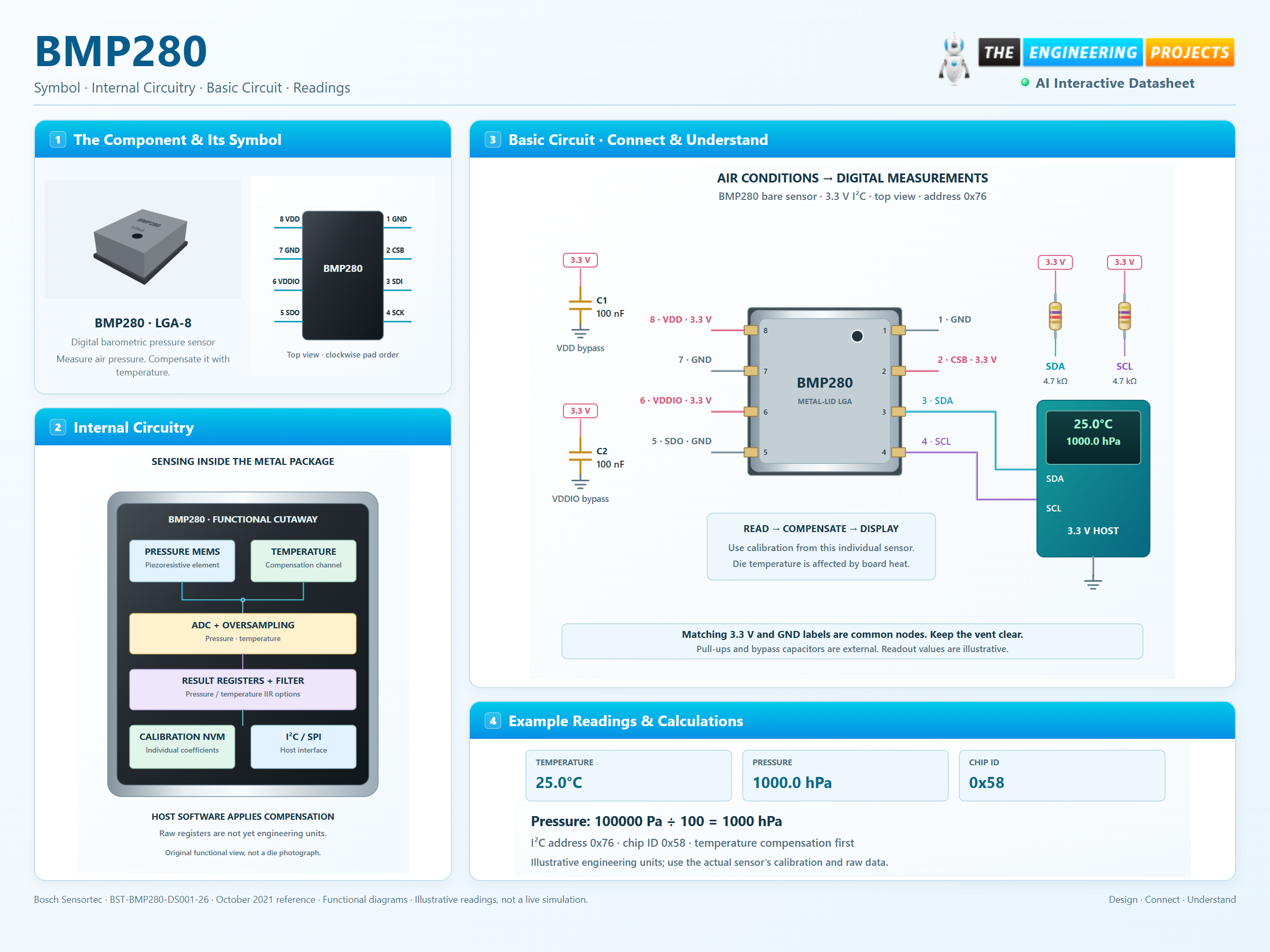
3 stages · Explore one step at a time
Supply both domains, wait for startup and NVM copying, then confirm chip ID 0x58 at register 0xD0.
write ctrl_meas 0xF4 = 0x25 for ×1 temperature, ×1 pressure and forced mode. Wait for this conversion to complete.
Burst-read six bytes from 0xF7. Decode raw fields, use this sensor’s calibration and convert pressure from Pa to hPa by dividing by 100.
Metal-lid sensor, two supply capacitors and a level-compatible host.
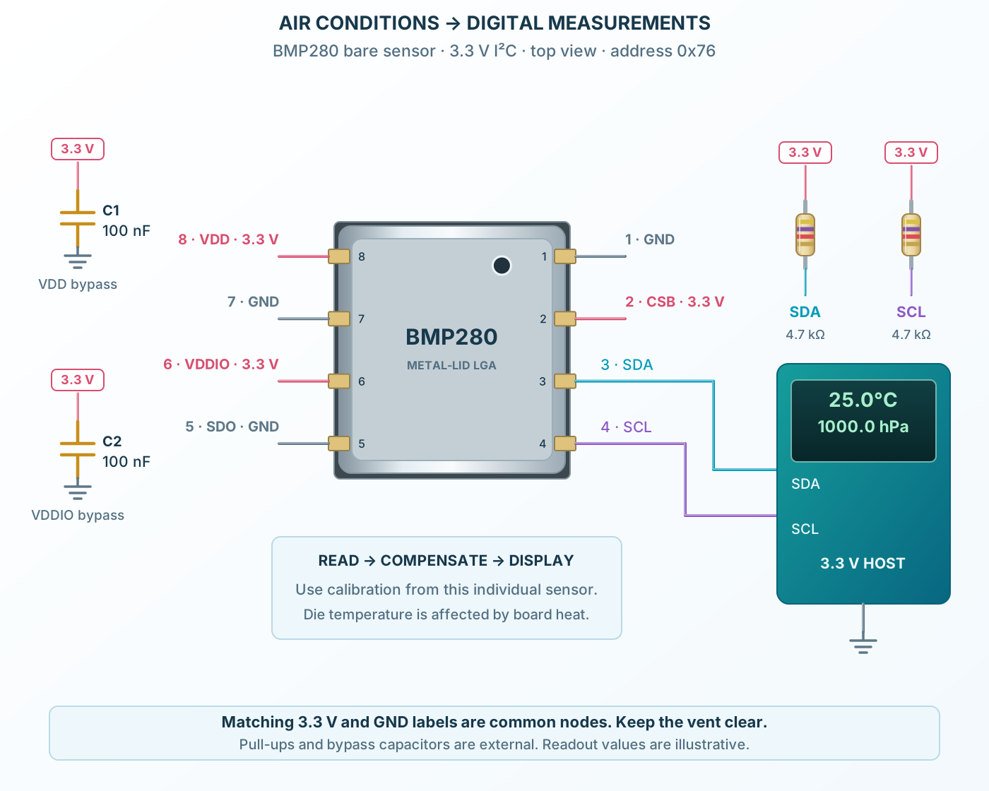
Follow the component values and pin connections
Bypass VDD and VDDIO independently.
Tie CSB high and SDO low for I²C address 0x76.
Read calibrated engineering units through the host firmware.
A compact sensing and conversion path inside the metal package.
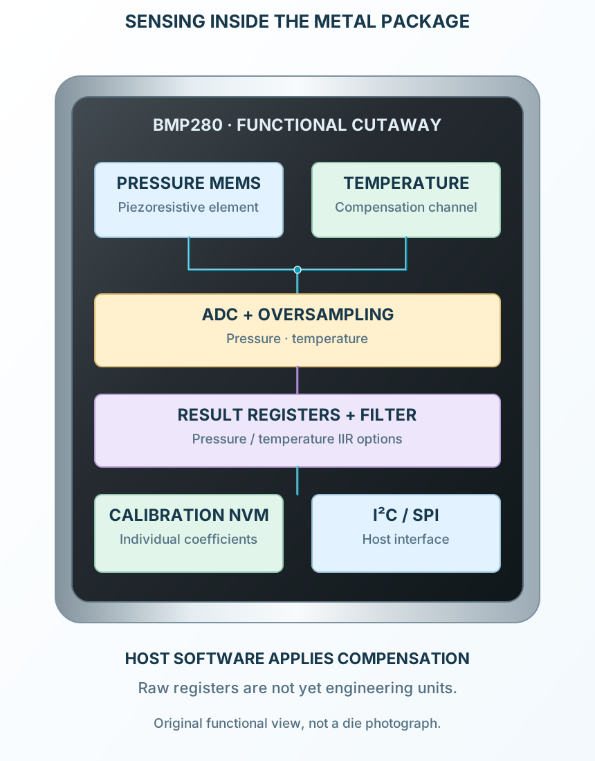
Select a stage to see its role and connections
A piezoresistive MEMS element responds to absolute pressure.
Oversampling and filtering control noise and response.
The host combines raw results with individual calibration coefficients.
Signal names, electrical functions and connection guidance
Scroll within the table to see all columns and rows.
| Pin | Signal | Type | Function & connection |
|---|---|---|---|
| GND | Ground | First ground pad.Connection guidanceJoin common ground; connect pad 7 too. | |
| CSB | Active-low SPI select | Selects the digital interface.Connection guidanceTie directly to VDDIO for I²C; use controller chip-select for SPI. For I²C it must already be high during power-on reset. | |
| SDI / SDA | Serial data | SPI input, shared three-wire data or I²C bidirectional data.Connection guidanceConnect to 3.3 V controller SDA and a 4.7 kΩ pull-up in the example. | |
| SCK / SCL | Serial clock | SPI or I²C clock from the host.Connection guidanceConnect to controller SCL with a pull-up to VDDIO for I²C. | |
| SDO / ADDR | SPI output / I²C address | SPI serial output; the I²C address bit is sampled from its level.Connection guidanceTie to GND for 0x76 or VDDIO for 0x77 in I²C. Do not leave floating in I²C; unconnected in three-wire SPI. | |
| VDDIO | Interface supply | Supplies the digital input/output domain.Connection guidanceUse 3.3 V and 100 nF to GND in this example. Operating range 1.2–3.6 V; no 5 V bus pull-ups. | |
| GND | Ground | Second ground pad.Connection guidanceJoin pad 1 and controller ground. | |
| VDD | Sensor supply | Powers the analog sensing and conversion circuitry.Connection guidanceUse 3.3 V and a separate 100 nF to GND. Operating range 1.71–3.6 V. |
No pins match these filters. Try another signal name or reset the filters.
Recommended operating conditions
Scroll within the table to see all columns and rows.
| Parameter | Value | Conditions / notes |
|---|---|---|
| VDD main supply | 1.71–3.6 V | 3.3 V in the example |
| VDDIO supply | 1.2–3.6 V | Sets the digital logic domain |
| Operating temperature | −40 to +85°C | Accuracy conditions are narrower |
| Pressure range | 300–1100 hPa | Absolute pressure |
| Humidity channel | Not present | Use BME280 if humidity is required |
| Startup before communication | 2 ms | Also wait until status.im_update clears |
| Sleep current | 0.1 µA typical | Sensor sleep; excludes external pull-ups and controller |
No specifications match. Try a parameter name or a unit.
Do not connect 5 V logic or pull-ups to the bare sensor.
Typical or stated accuracy conditions
Scroll within the table to see all columns and rows.
| Parameter | Value | Conditions / notes |
|---|---|---|
| Pressure absolute accuracy | ±1 hPa typical | 950–1050 hPa, 0–40°C |
| Relative pressure accuracy | ±0.12 hPa | 700–900 hPa; 25°C |
| Temperature accuracy | ±0.5°C at 25°C | Internal die temperature; board heating affects ambient estimates |
| Pressure resolution | 0.16 Pa | Output resolution is not accuracy |
| Typical pressure noise | 1.3 Pa RMS | Highest resolution, full bandwidth |
| Filtered pressure noise | 0.2 Pa RMS typical | Highest oversampling and lowest bandwidth |
| Typical current at 1 Hz | 2.7 µA | Pressure and temperature |
No specifications match. Try a parameter name or a unit.
Resolution, noise, accuracy and conversion speed describe different limitations.
I²C and SPI configuration
Scroll within the table to see all columns and rows.
| Parameter | Value | Conditions / notes |
|---|---|---|
| I²C chip selection | CSB2 tied to VDDIO | Required from power-on reset |
| I²C data / clock | SDI3 = SDA; SCK4 = SCL | Pull both bus lines to VDDIO |
| SDO5 low / high | 0x76 / 0x77 | Seven-bit addresses; do not float |
| I²C maximum clock | 3.4 MHz | Use the required high-speed protocol; example is 100 kHz |
| SPI maximum clock | 10 MHz | Observe setup, hold and output delay conditions |
| 4-wire SPI | CSB, SCK, SDI, SDO | Separate input and output data |
| 3-wire SPI | CSB, SCK and shared SDI | Set spi3w_en; SDO is unused |
No specifications match. Try a parameter name or a unit.
A module may contain its own pull-ups or regulator. Inspect its schematic separately.
Read whole measurement groups coherently
Scroll within the table to see all columns and rows.
| Parameter | Value | Conditions / notes |
|---|---|---|
| 0xD0 chip ID | 0x58 | Distinguishes the selected part |
| 0xE0 reset | Write 0xB6 | Wait for startup / coefficient copy |
| 0xF3 status | Bit 3 measuring; bit 0 im_update | Do not read an old result as a just-triggered conversion |
| 0xF4 ctrl_meas | Temperature / pressure oversampling and mode | Example 0x25 = ×1 / ×1 / forced |
| 0xF5 config | Standby time, IIR and 3-wire selection | Configure in sleep; example filter off |
| 0xF7–0xFC | 20-bit pressure + 20-bit temperature | MSB, LSB and upper nibble of XLSB |
| Calibration | Temperature / pressure from 0x88 onward | Use each chip’s stored coefficients |
No specifications match. Try a parameter name or a unit.
Preserve signed coefficient types and packed fields; raw ADC data is not already °C, Pa or % RH.
Noise, response and current trade-offs
Scroll within the table to see all columns and rows.
| Parameter | Value | Conditions / notes |
|---|---|---|
| Sleep | No measurements | Registers remain accessible |
| Forced | One measurement, then sleep | Host triggers the next result |
| Normal | Repeated measurement and standby | Choose standby for the required update rate |
| Oversampling | Skipped or ×1 / ×2 / ×4 / ×8 / ×16 | Each enabled channel configured separately |
| IIR | Off / 2 / 4 / 8 / 16 | Pressure and temperature; not humidity |
| Example conversion maximum | 6.425 ms | ×1 temperature and pressure; manufacturer timing formula |
| Fresh result check | Wait for the conversion to finish | Allow the full bounded duration or observe the busy-to-idle transition |
No specifications match. Try a parameter name or a unit.
Firmware must allow startup and bus time as well as the acquisition itself.
A bare-sensor connection
Scroll within the table to see all columns and rows.
| Parameter | Value | Conditions / notes |
|---|---|---|
| VDD8 and VDDIO6 | 3.3 V | Separate 100 nF capacitors to common ground |
| GND1 and GND7 | Common ground | Connect both pads |
| CSB2 | 3.3 V | Select I²C from startup |
| SDO5 | GND | Address 0x76 |
| SDA3 and SCL4 | 3.3 V controller | 4.7 kΩ example pull-ups; verify bus rise time |
| Firmware order | Reset / wait / coefficients / configuration / convert / read | Temperature compensation before dependent channels |
| Display examples | 25.0°C · 1000.0 hPa | Illustrative engineering-unit values, not live readings |
No specifications match. Try a parameter name or a unit.
The display belongs to the host system, not the sensor package.
Clockwise top-view numbering
Scroll within the table to see all columns and rows.
| Parameter | Value | Conditions / notes |
|---|---|---|
| Package body | 2 × 2.5 × 0.95 mm | Eight-contact metal-lid LGA |
| Pad pitch | 0.65 mm | Four contacts on each of two opposite sides |
| Top-view order | Right: 1,2,3,4 · left: 8,7,6,5 | Top to bottom; bottom view is mirrored |
| Vent opening | Keep clear | Avoid coating, adhesive or contamination in the port |
| Thermal placement | Away from hot ICs and airflow artifacts | Temperature senses package conditions |
| PCB lands | Authored 0.50 × 0.35 mm; 1.50 mm row centers | Starting pattern checked against the package outline |
| Humidity handling | No humidity sensing element | Review the complete manufacturer assembly instructions |
No specifications match. Try a parameter name or a unit.
The bare IC and a breakout module have different size, pinout and supporting circuitry.
No matching rowsTry a pin name, parameter, unit or test condition, or reset the filters.
Log compensated atmospheric pressure and die temperature.
Manufacturer application guideUse pressure changes with an appropriate atmospheric model and reference pressure.
Manufacturer application guideUse forced acquisitions and sleep between host-requested samples.
Manufacturer application guideFind BMP280 in the Components Library to place its schematic symbol and connect its pins.
Working Arduino sensor example available in ProTechOpen ProTech