Real View
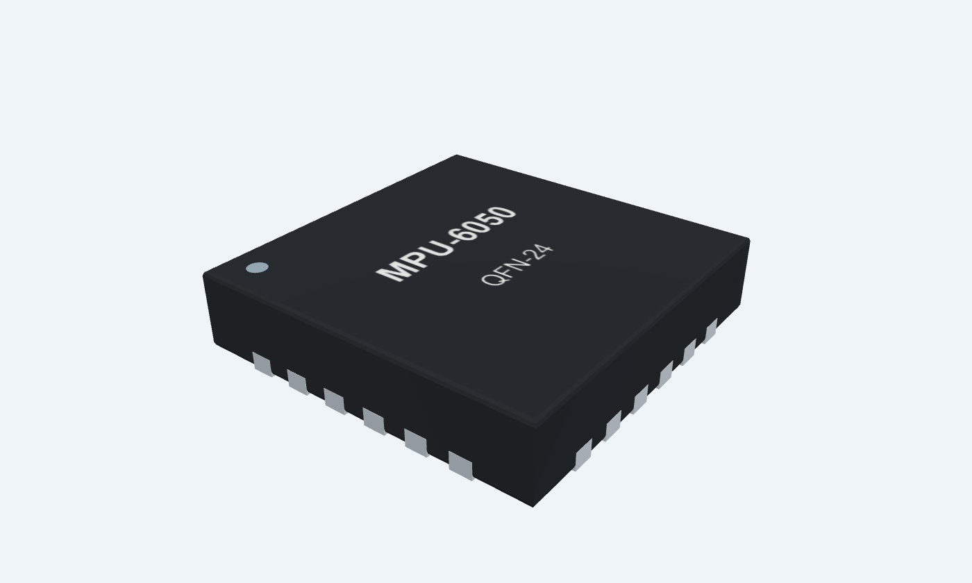
Measure acceleration and rotation in three dimensions.
MPU6050 combines a three-axis accelerometer and three-axis gyroscope with 16-bit conversion in a 4 mm QFN package. Selectable ranges cover ±2 to ±16 g and ±250 to ±2000 degrees per second; a temperature channel, digital filters and a 1024-byte FIFO support motion acquisition. Its main host interface is I²C, with an auxiliary I²C master for external sensors. It has no built-in magnetometer, and SPI support in the combined manufacturer document belongs to MPU6000. The bare MPU6050 needs VDD, VLOGIC and the specified regulator and charge-pump capacitors. Read each signed measurement using the configured scale, remove measured offsets and account for the sensor axes. Acceleration includes gravity, while gyro output is angular rate rather than an absolute angle. This page follows the original MPU6050 package and assembly rules, including leaving its exposed die pad unsoldered.
Click a lead or use the arrow keys. Top view · counterclockwise numbering
Optional external reference clock.
Ground when unused; the example uses an internal gyro PLL.
Not internally connected.
No external connection is needed.
Not internally connected.
No external connection is needed.
Not internally connected.
No external connection is needed.
Not internally connected.
No external connection is needed.
Auxiliary I²C master data for an external sensor.
Leave open when the auxiliary interface is disabled.
Auxiliary I²C master clock.
Leave open when unused.
Digital interface supply for MPU-6050.
Use 1.71 V to VDD and a local 10 nF bypass.
This is not the chip-select pin found on MPU-6000.
Least-significant bit of the seven-bit I²C address.
Ground selects 0x68; VLOGIC selects 0x69.
Internal regulator output requiring a filter capacitor.
Connect 100 nF X7R to ground; do not drive this pin.
External frame synchronization input.
Ground when unused.
Configurable interrupt; push-pull or open-drain.
Connect to a host interrupt input or leave open when unused.
Sensor power supply.
Use 2.375–3.46 V with a local 100 nF bypass.
The bare chip is not a 5 V part.
Not internally connected.
No external connection is needed.
Not internally connected.
No external connection is needed.
Not internally connected.
No external connection is needed.
Not internally connected.
No external connection is needed.
Power and signal ground.
Connect to common host ground.
Reserved package contact.
Do not connect.
Internal charge-pump capacitor connection.
Use 2.2 nF X7R, ±10%, 50 V to ground.
This is a filter node, not a power output for external circuitry.
Reserved package contact.
Do not connect.
Reserved on MPU-6050.
Do not connect.
Primary I²C serial clock.
Connect to host SCL with a pullup to VLOGIC.
Primary I²C serial data.
Connect to host SDA with a pullup to VLOGIC.
Six-axis accelerometer and gyroscope
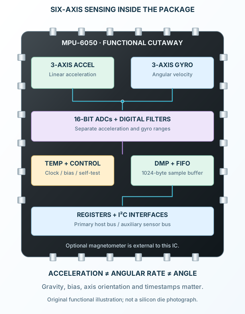
MEMS acceleration and angular-rate channels pass through conversion and digital filtering. The host can read raw measurements, drain the FIFO or use supported motion-processing software. Temperature is a separate on-die reading.
MPU-6050
Key parameters and their test conditions
Follows the selected physical package
Select a pin to open its function, electrical notes and wiring guidance.
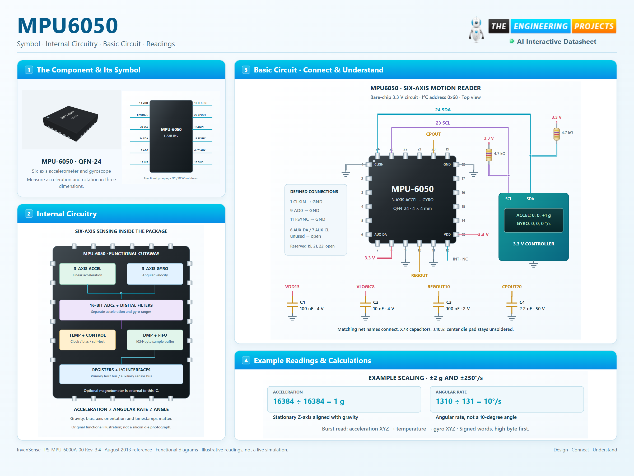
Set the clock, ranges, filter and sample divider before acquisition.
Read 14 bytes from 0x3B: acceleration XYZ, temperature, then gyro XYZ.
Combine high and low bytes as signed 16-bit values, apply the selected sensitivity and remove measured offsets.
At ±2 g, divide acceleration counts by 16384. At ±250°/s, divide gyro counts by 131. Integrating gyro rate needs time and bias calibration; it does not provide an absolute compass heading.
Select a pin to explore its function and connection.
| Pin | Signal | Type | Function |
|---|---|---|---|
| CLKIN | Input | Optional external reference clock. | |
| NC | No connection | Not internally connected. | |
| NC | No connection | Not internally connected. | |
| NC | No connection | Not internally connected. | |
| NC | No connection | Not internally connected. | |
| AUX_DA | Bidirectional | Auxiliary I²C master data for an external sensor. | |
| AUX_CL | Output | Auxiliary I²C master clock. | |
| VLOGIC | Supply | Digital interface supply for MPU-6050. | |
| AD0 | Input | Least-significant bit of the seven-bit I²C address. | |
| REGOUT | Regulator filter | Internal regulator output requiring a filter capacitor. | |
| FSYNC | Input | External frame synchronization input. | |
| INT | Output | Configurable interrupt; push-pull or open-drain. | |
| VDD | Supply | Sensor power supply. | |
| NC | No connection | Not internally connected. | |
| NC | No connection | Not internally connected. | |
| NC | No connection | Not internally connected. | |
| NC | No connection | Not internally connected. | |
| GND | Return | Power and signal ground. | |
| RESV | Reserved | Reserved package contact. | |
| CPOUT | Charge-pump filter | Internal charge-pump capacitor connection. | |
| RESV | Reserved | Reserved package contact. | |
| RESV | Reserved | Reserved on MPU-6050. | |
| SCL | Input | Primary I²C serial clock. | |
| SDA | Bidirectional | Primary I²C serial data. |
No pins match. Try a signal name or choose All pins.
Bare sensor; breakout-board limits may differ
| Parameter | Value | Conditions / notes |
|---|---|---|
| VDD | 2.375–3.46 V | Sensor supply; example uses 3.3 V |
| VLOGIC | 1.71 V to VDD | Must not exceed VDD, including during power transitions |
| Primary interface | I²C up to 400 kHz | MPU6050 has no primary SPI interface |
| I²C address | 0x68 / 0x69 | AD0 grounded / tied to VLOGIC |
| Gyro + accelerometer current | 3.8 mA typical | Normal operating mode; DMP disabled |
| Gyro + accelerometer + DMP | 3.9 mA typical | Typical normal-operation value |
| Sleep current | 5 µA typical | Excludes the separate interface-rail contribution |
| Operating temperature | −40°C to +85°C | Calibrate offsets across the intended conditions |
No specifications match. Try a parameter name or a unit.
Observe the manufacturer power-on sequence and supply ramp requirements.
16-bit signed sensor outputs
| Parameter | Value | Conditions / notes |
|---|---|---|
| Accelerometer ±2 / ±4 g | 16384 / 8192 LSB per g | ACCEL_CONFIG AFS_SEL = 0 / 1 |
| Accelerometer ±8 / ±16 g | 4096 / 2048 LSB per g | AFS_SEL = 2 / 3 |
| Gyroscope ±250 / ±500°/s | 131 / 65.5 LSB per °/s | GYRO_CONFIG FS_SEL = 0 / 1 |
| Gyroscope ±1000 / ±2000°/s | 32.8 / 16.4 LSB per °/s | FS_SEL = 2 / 3 |
| Temperature conversion | Signed raw / 340 + 36.53°C | On-die temperature, not a calibrated ambient thermometer |
| Stationary acceleration | Approximately 1 g total magnitude | Gravity remains in the accelerometer reading |
| Initial gyro zero-rate offset | Up to ±20°/s | Calibration is needed for meaningful integration |
| Initial accelerometer offset | X/Y: ±50 mg; Z: ±80 mg | Manufacturer initial zero-g tolerances |
No specifications match. Try a parameter name or a unit.
An angular-rate reading is not an absolute orientation.
RM-MPU-6000A-00 Rev. 4.2
| Parameter | Value | Conditions / notes |
|---|---|---|
| WHO_AM_I | 0x75 → 0x68 | Does not change when AD0 selects address 0x69 |
| PWR_MGMT_1 | 0x6B | Reset default is sleep; example writes 0x01 for X-gyro PLL |
| CONFIG | 0x1A → 0x03 | Example filter: gyro 42 Hz, acceleration 44 Hz |
| SMPLRT_DIV | 0x19 → 0x09 | With the enabled DLPF: 1000 / (1 + 9) = 100 Hz |
| GYRO_CONFIG | 0x1B → 0x00 | Example ±250°/s, self-test off |
| ACCEL_CONFIG | 0x1C → 0x00 | Example ±2 g, self-test off |
| INT_ENABLE / INT_STATUS | 0x38 / 0x3A | Bit 0 selects / reports data-ready |
| Coherent measurement burst | 0x3B–0x48, 14 bytes | Accel XYZ, temperature, gyro XYZ; high byte first |
| FIFO count / data | 0x72–0x73 / 0x74 | FIFO capacity is 1024 bytes; handle overflow |
No specifications match. Try a parameter name or a unit.
Register reference: https://netsonic.fi/en/files/MPU6050-datasheet.pdf
Filter settings affect rate and latency
| Parameter | Value | Conditions / notes |
|---|---|---|
| Output sample formula | Gyro output rate / (1 + SMPLRT_DIV) | Divider is an unsigned byte |
| DLPF configurations 1–6 | 1 kHz gyro base rate | Valid low-pass-filter settings |
| DLPF configuration 0 | 8 kHz gyro base rate | Do not use reserved configuration 7 |
| Accelerometer base rate | 1 kHz | Higher output rates can repeat acceleration samples |
| Example 100 Hz acquisition | DLPF = 3, divider = 9 | 10 ms sample interval before host scheduling effects |
| Signed conversion | int16((high << 8) | low) | Sign extension matters for negative motion |
| Rate-to-angle integration | Angle change ≈ corrected rate × elapsed time | Gyro bias accumulates as drift |
| Nine-axis claims | Requires an external magnetometer | None is built into MPU6050 |
No specifications match. Try a parameter name or a unit.
The illustrated readings are examples, not live measurements.
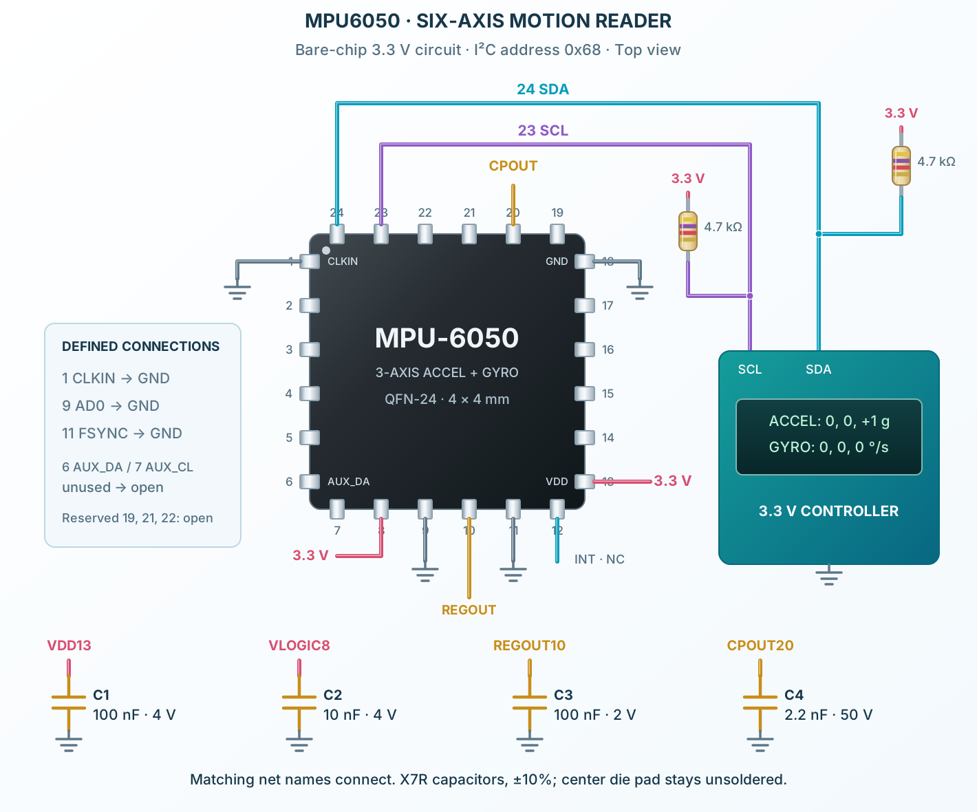
Manufacturer typical operating circuit
| Parameter | Value | Conditions / notes |
|---|---|---|
| VDD13 bypass | 100 nF, X7R, ±10%, ≥4 V | Place near pin 13 |
| VLOGIC8 bypass | 10 nF, X7R, ±10%, ≥4 V | Separate interface-rail bypass |
| REGOUT10 filter | 100 nF, X7R, ±10%, ≥2 V | Connect only the filter capacitor to ground |
| CPOUT20 filter | 2.2 nF, X7R, ±10%, 50 V | Do not replace with a low-voltage supply bypass |
| SDA24 / SCL23 | Pullups to VLOGIC | 4.7 kΩ shown for a short example bus; size for capacitance |
| Unused external clocks | CLKIN1 and FSYNC11 → GND | Do not leave these unused inputs floating |
| Unused auxiliary interface | AUX_DA6 / AUX_CL7 open | Keep the auxiliary master disabled |
| Reserved contacts | 19, 21, 22 unconnected | NC and reserved are not interchangeable instructions |
No specifications match. Try a parameter name or a unit.
3.3 V is within both rail ranges. This is not a 5 V breakout circuit.
Original manufacturer land guidance
| Parameter | Value | Conditions / notes |
|---|---|---|
| Body / height | 4 × 4 × 0.90 mm nominal | 24 contacts on four sides |
| Contact pitch | 0.50 mm | Pin 1 upper-left; counterclockwise top view |
| Perimeter copper lands | 0.35 mm wide; 0.80 / 0.85 mm long | Longer lands at each bank end; outer span 4.80 mm |
| Exposed die pad | 2.70 × 2.60 mm on the package | No internal electrical connection |
| Center solder land | Intentionally omitted | Manufacturer section 11.4.2 says do not solder the exposed pad |
| Routing beneath the die pad | No traces or vias beneath that pad | Follow section 11.4.3 shielding/ground-plane advice |
| Mechanical stress | Keep large insertion components away | Manufacturer recommends at least 6 mm separation |
| Physical axes | Follow package top-view axes | Board mounting errors cause cross-axis response |
No specifications match. Try a parameter name or a unit.
Do not substitute a generic QFN footprint with a soldered thermal pad.
Track acceleration and angular velocity with calibration and timestamps.
Manufacturer application guideFuse acceleration and rate measurements within the control-system bandwidth.
Manufacturer application guideUse sampling, filters and thresholds appropriate to the expected movement.
Manufacturer application guideFind MPU6050 in the Components Library to place its schematic symbol and connect its pins.
Reference page · circuit simulation model not yet availableOpen ProTech