SHT31SHT31-DIS digital humidity and temperature sensor
Two calibrated measurements on a checked I²C connection.
SHT31-DIS combines humidity and temperature sensing with factory calibration and an I²C interface. A controller can request one measurement or select periodic acquisition. Each returned measurement word has its own CRC byte, allowing corrupted transfers to be rejected before the display or control logic uses them. The compact DFN package has eight perimeter contacts and an underside ground pad. A supply bypass capacitor and two bus pullups complete the basic interface. ADDR selects 0x44 or 0x45; the optional ALERT and reset connections support more advanced designs. This page covers the SHT31 digital variant. Follow its package orientation and keep the sensing opening exposed to the air. A fast bus transaction does not mean the physical humidity and temperature have changed equally quickly; airflow, mounting and nearby heat sources affect the reading.
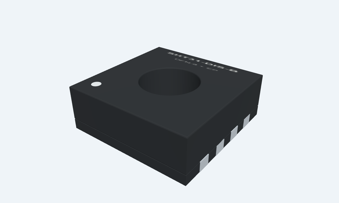

9Physical pins
SHT31-DIS-BDFN-8 + EP
Manufacturer-referencedSensirion
Pin diagram
Select a pin to explore its connection
Highlight
SHT31DFN-8 + EPTop view · contact 9 is the underside ground pad
Click a lead or use the arrow keys. Top view · contact 9 is the underside ground pad
PIN 1 · Serial data
Bidirectional dataSDA
Function
I²C data connection.
How to connect
Pull up to the logic rail; connect to the controller SDA.
Electrical note
Open-drain; choose the pullup for bus capacitance and frequency.
PIN 2 · Address strap
Address selectionADDR
Function
Selects the seven-bit bus address.
How to connect
Tie LOW for 0x44 or HIGH for 0x45; do not leave floating.
Electrical note
Keep stable throughout the I²C transaction.
PIN 3 · Alert
Alert outputALERT
Function
Indicates configured temperature or humidity limits.
How to connect
Connect to a compatible controller input, or leave open if unused.
PIN 4 · Serial clock
Serial clockSCL
Function
I²C clock connection.
How to connect
Connect to controller SCL with an external pullup.
Electrical note
Choose a controller that supports clock stretching if that command mode is used.
PIN 5 · Supply
SupplyVDD
Function
Positive sensor rail.
How to connect
Use 2.15–5.5 V with 100 nF close to VDD/VSS.
PIN 6 · Reset
Active-low resetnRESET
Function
Resets the sensor when pulled LOW.
How to connect
May be left open when unused; an optional pullup to VDD must be at least 2 kΩ.
Electrical note
Do not hard-wire this input directly to VDD.
PIN 7 · Ground
Reserved contactR
Function
No functional signal.
How to connect
Connect to VSS as directed by the datasheet.
PIN 8 · Ground
GroundVSS
Function
Supply and interface return.
How to connect
Connect to controller ground.
PIN 9 · Ground
Exposed center padEP
Function
Underside pad, internally connected to VSS.
How to connect
Solder to a ground land for mechanical support.
Electrical note
Contact 9 is the footprint identifier for the unnumbered die pad, not a ninth perimeter pin.
Key specifications
Write a 16-bit measurement command, wait for completion or use clock stretching, then read temperature and humidity with separate CRC checks.
Supply2.15–5.5 V
Typical humidity error±2 %RH · see tolerance curves
Typical temperature error±0.2 °C · 0–90°C
I²C addresses44 / 45 hex · seven-bit
Package details
SHT31-DIS-B · DFN-8 + EP
| Property | Details |
|---|---|
| Manufacturer | Sensirion |
| Part number | SHT31-DIS-B |
| Package | DFN-8 + EP |
| Connections | 9 pins |
| Mounting | SMD |
| Lead pitch | 0.50 mm |
| Package code | DFN-8 |
| Thermal reference | −40°C to +125°C · reference conditions apply |
Power and operating conditions
Digital SHT31-DIS variant
Manufacturer specifications 6 parameters
Scroll sideways to see all columns.
| Parameter | Value | Conditions / notes |
|---|---|---|
| Supply | 2.15–5.5 V | 3.3 V in the example |
| Local bypass | 100 nF | Place close to VDD and VSS |
| Idle / conversion current | 0.2 µA / 600 µA typical | Single-shot idle at 25°C; conversion 1.5 mA maximum |
| Specified ranges | −40°C to +125°C; 0–100%RH | Extended range; normal conditions are narrower |
| Recommended normal operation | 5–60°C and 20–80%RH | Long exposure outside this region can change sensor behavior |
| Bus pullups | 4.7 kΩ in the example | An illustrative short 100 kHz bus; calculate for the real load |
No specifications match. Try a parameter name or a unit.
Do not confuse operating limits with absolute maximum ratings.
Accuracy and response
SHT31 grade; do not substitute SHT35 limits
Manufacturer specifications 6 parameters
Scroll sideways to see all columns.
| Parameter | Value | Conditions / notes |
|---|---|---|
| Humidity tolerance | ±2%RH typical | Use the manufacturer curves for range-dependent maxima |
| Temperature tolerance | ±0.2°C typical over 0–90°C | See the temperature error curve outside this range |
| Humidity repeatability | 0.08%RH typical, high setting | A noise metric, distinct from absolute accuracy |
| Temperature repeatability | 0.04°C typical, high setting | A noise metric, distinct from absolute accuracy |
| Humidity response | 8 s typical to 63% | 25°C, 1 m/s airflow, without ART |
| Temperature response | Greater than 2 s | Depends strongly on mounting and heat exchange |
No specifications match. Try a parameter name or a unit.
A 16-bit result is not a promise of 16-bit measurement accuracy.
Useful command reference
Two-byte command values
Manufacturer specifications 8 parameters
Scroll sideways to see all columns.
| Parameter | Value | Conditions / notes |
|---|---|---|
| Single shot, high repeatability | 0x2400 / 0x2C06 | Without / with clock stretching |
| Single shot, medium repeatability | 0x240B / 0x2C0D | Without / with clock stretching |
| Single shot, low repeatability | 0x2416 / 0x2C10 | Without / with clock stretching |
| Periodic, 1 sample/s, high | 0x2130 | Fetch with 0xE000 |
| Exit periodic mode | 0x3093 | Break command |
| Soft reset | 0x30A2 | Allow the reset recovery time |
| Read / clear status | 0xF32D / 0x3041 | Status is a checked 16-bit word |
| Heater enable / disable | 0x306D / 0x3066 | Heater raises sensor temperature; not normal ambient measurement |
No specifications match. Try a parameter name or a unit.
Use explicit error handling for NACKs and communication timeouts.
Six-byte response and equations
Temperature first, humidity second
Manufacturer specifications 7 parameters
Scroll sideways to see all columns.
| Parameter | Value | Conditions / notes |
|---|---|---|
| Bytes 0–2 | Temperature MSB, LSB, CRC | Unsigned raw word ST |
| Bytes 3–5 | Humidity MSB, LSB, CRC | Unsigned raw word SRH |
| Temperature | T = −45 + 175 × ST / 65535 | Result in °C |
| Relative humidity | RH = 100 × SRH / 65535 | Result in %RH |
| CRC-8 | Polynomial 0x31; initial 0xFF | No reflection; final XOR 0; reset for each word |
| Reference check | CRC(BE EF) = 92 hex | Manufacturer test vector |
| Illustrative response | 66 66 93 80 00 A2 hex | 25.00°C and approximately 50.00%RH |
No specifications match. Try a parameter name or a unit.
Check all six bytes before updating the displayed measurements.
Conversion and interface timing
Supply-dependent maximum conversion time
Manufacturer specifications 7 parameters
Scroll sideways to see all columns.
| Parameter | Value | Conditions / notes |
|---|---|---|
| High repeatability | 15 ms at 2.4–5.5 V | 15.5 ms at 2.15 V to below 2.4 V |
| Medium repeatability | 6 ms at 2.4–5.5 V | 6.5 ms at 2.15 V to below 2.4 V |
| Low repeatability | 4 ms at 2.4–5.5 V | 4.5 ms at 2.15 V to below 2.4 V |
| Power-up | 1 ms maximum at 2.4–5.5 V | 1.5 ms in the lower supply range |
| Soft reset | 1.5 ms maximum | Wait before another command |
| Supported I²C clock | Up to 1 MHz | Respect the electrical and rise-time limits |
| Periodic rates | 0.5, 1, 2, 4 or 10 samples/s | Do not mistake sample rate for environmental response time |
No specifications match. Try a parameter name or a unit.
Choose command mode, bus speed and power budget together.
Pin straps and package
Top-view numbering; underside pad identified separately
Manufacturer specifications 7 parameters
Scroll sideways to see all columns.
| Parameter | Value | Conditions / notes |
|---|---|---|
| ADDR | VSS → 0x44; VDD → 0x45 | Never leave floating |
| R contact 7 | Connect to VSS | Not a spare GPIO |
| ALERT | Leave open if unused | Optional alarm output |
| nRESET | Leave open if unused | Optional pullup must be at least 2 kΩ |
| Center pad | Internally connected to VSS | Soldering supports the package mechanically |
| DFN outline | 2.5 × 2.5 × 0.9 mm nominal | Eight 0.5 mm-pitch perimeter contacts |
| Authored land pattern | 0.55 × 0.25 mm signal lands | 1.0 × 1.7 mm rectangular center land; review mask and paste |
No specifications match. Try a parameter name or a unit.
Keep the sensing opening free of coating, flux residue and enclosure obstructions.
Connections by function
Select a pin for its function, connection guidance and electrical notes.
Serial data1 pin
Address strap1 pin
Alert1 pin
Serial clock1 pin
Supply1 pin
Reset1 pin
Ground3 pins
SHT31 at a glance
Follow the labeled connections and functional stages
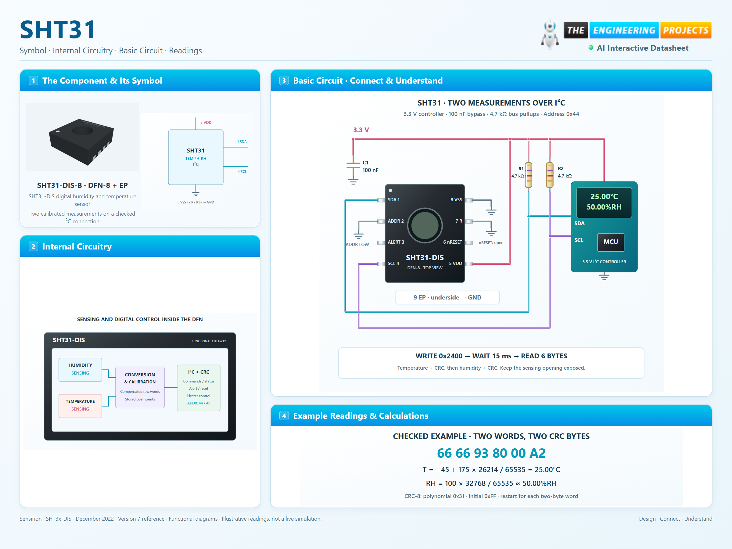
How it works
3 stages · Explore one step at a time
Select the measurement
At address 0x44, send 0x2400 for a high-repeatability single conversion without clock stretching.
Wait for completion
At 3.3 V, allow the 15 ms maximum conversion time before reading. Lower supply operation has a longer bound.
Validate and scale
Check both CRCs, then scale the unsigned raw words into Celsius and percent humidity.
Step 1 of 3
SHT31 in a circuit
A physical sensor, two bus pullups and local bypassing.
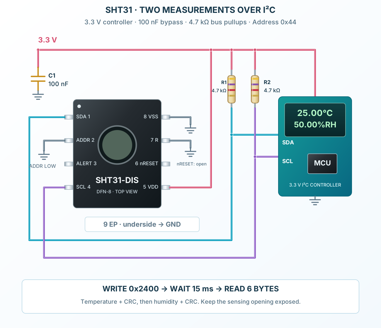
Connect it, step by step
Follow the component values and pin connections
Power and ground
Bypass VDD, connect VSS and the center land, and keep the opening clear.
Wire the bus
Fit SDA and SCL pullups to 3.3 V and strap ADDR LOW.
Check each word
Issue the conversion command, wait, then validate temperature and humidity separately.
Inside SHT31
Sensing, conversion and digital control inside the DFN body.
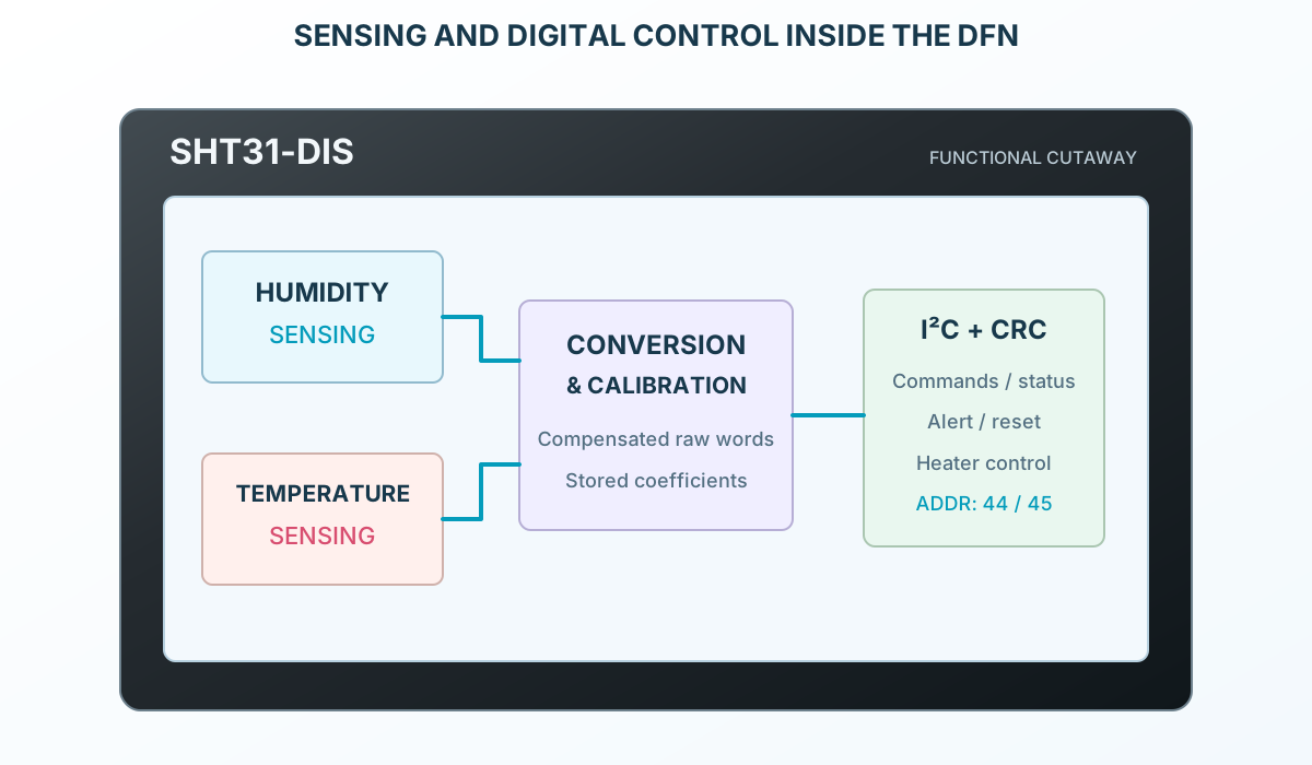
Explore the circuit
Select a stage to see its role and connections
Convert the sensor signals
The sensing and conversion stages measure the local environment.
Apply stored calibration
The device returns compensated digital measurement words.
Transfer with checks
The I²C interface provides commands, status and separate CRC bytes.
Selected packageDFN-8 + EPSHT31-DIS-B
Physical connections9 pinsPackage-specific numbering
Reference collection7 tables41 parameters & pin functions
Pin reference
Signal names, electrical functions and connection guidance
Physical pin numbers9 pins
Scroll within the table to see all columns and rows.
| Pin | Signal | Type | Function & connection |
|---|---|---|---|
| SDA | Bidirectional data | I²C data connection.Connection guidancePull up to the logic rail; connect to the controller SDA. Open-drain; choose the pullup for bus capacitance and frequency. | |
| ADDR | Address selection | Selects the seven-bit bus address.Connection guidanceTie LOW for 0x44 or HIGH for 0x45; do not leave floating. Keep stable throughout the I²C transaction. | |
| ALERT | Alert output | Indicates configured temperature or humidity limits.Connection guidanceConnect to a compatible controller input, or leave open if unused. | |
| SCL | Serial clock | I²C clock connection.Connection guidanceConnect to controller SCL with an external pullup. Choose a controller that supports clock stretching if that command mode is used. | |
| VDD | Supply | Positive sensor rail.Connection guidanceUse 2.15–5.5 V with 100 nF close to VDD/VSS. | |
| nRESET | Active-low reset | Resets the sensor when pulled LOW.Connection guidanceMay be left open when unused; an optional pullup to VDD must be at least 2 kΩ. Do not hard-wire this input directly to VDD. | |
| R | Reserved contact | No functional signal.Connection guidanceConnect to VSS as directed by the datasheet. | |
| VSS | Ground | Supply and interface return.Connection guidanceConnect to controller ground. | |
| EP | Exposed center pad | Underside pad, internally connected to VSS.Connection guidanceSolder to a ground land for mechanical support. Contact 9 is the footprint identifier for the unnumbered die pad, not a ninth perimeter pin. |
No pins match these filters. Try another signal name or reset the filters.
Power and operating conditions
Digital SHT31-DIS variant
Manufacturer-referenced values6 parameters
Scroll within the table to see all columns and rows.
| Parameter | Value | Conditions / notes |
|---|---|---|
| Supply | 2.15–5.5 V | 3.3 V in the example |
| Local bypass | 100 nF | Place close to VDD and VSS |
| Idle / conversion current | 0.2 µA / 600 µA typical | Single-shot idle at 25°C; conversion 1.5 mA maximum |
| Specified ranges | −40°C to +125°C; 0–100%RH | Extended range; normal conditions are narrower |
| Recommended normal operation | 5–60°C and 20–80%RH | Long exposure outside this region can change sensor behavior |
| Bus pullups | 4.7 kΩ in the example | An illustrative short 100 kHz bus; calculate for the real load |
No specifications match. Try a parameter name or a unit.
Do not confuse operating limits with absolute maximum ratings.
Accuracy and response
SHT31 grade; do not substitute SHT35 limits
Manufacturer-referenced values6 parameters
Scroll within the table to see all columns and rows.
| Parameter | Value | Conditions / notes |
|---|---|---|
| Humidity tolerance | ±2%RH typical | Use the manufacturer curves for range-dependent maxima |
| Temperature tolerance | ±0.2°C typical over 0–90°C | See the temperature error curve outside this range |
| Humidity repeatability | 0.08%RH typical, high setting | A noise metric, distinct from absolute accuracy |
| Temperature repeatability | 0.04°C typical, high setting | A noise metric, distinct from absolute accuracy |
| Humidity response | 8 s typical to 63% | 25°C, 1 m/s airflow, without ART |
| Temperature response | Greater than 2 s | Depends strongly on mounting and heat exchange |
No specifications match. Try a parameter name or a unit.
A 16-bit result is not a promise of 16-bit measurement accuracy.
Useful command reference
Two-byte command values
Manufacturer-referenced values8 parameters
Scroll within the table to see all columns and rows.
| Parameter | Value | Conditions / notes |
|---|---|---|
| Single shot, high repeatability | 0x2400 / 0x2C06 | Without / with clock stretching |
| Single shot, medium repeatability | 0x240B / 0x2C0D | Without / with clock stretching |
| Single shot, low repeatability | 0x2416 / 0x2C10 | Without / with clock stretching |
| Periodic, 1 sample/s, high | 0x2130 | Fetch with 0xE000 |
| Exit periodic mode | 0x3093 | Break command |
| Soft reset | 0x30A2 | Allow the reset recovery time |
| Read / clear status | 0xF32D / 0x3041 | Status is a checked 16-bit word |
| Heater enable / disable | 0x306D / 0x3066 | Heater raises sensor temperature; not normal ambient measurement |
No specifications match. Try a parameter name or a unit.
Use explicit error handling for NACKs and communication timeouts.
Six-byte response and equations
Temperature first, humidity second
Manufacturer-referenced values7 parameters
Scroll within the table to see all columns and rows.
| Parameter | Value | Conditions / notes |
|---|---|---|
| Bytes 0–2 | Temperature MSB, LSB, CRC | Unsigned raw word ST |
| Bytes 3–5 | Humidity MSB, LSB, CRC | Unsigned raw word SRH |
| Temperature | T = −45 + 175 × ST / 65535 | Result in °C |
| Relative humidity | RH = 100 × SRH / 65535 | Result in %RH |
| CRC-8 | Polynomial 0x31; initial 0xFF | No reflection; final XOR 0; reset for each word |
| Reference check | CRC(BE EF) = 92 hex | Manufacturer test vector |
| Illustrative response | 66 66 93 80 00 A2 hex | 25.00°C and approximately 50.00%RH |
No specifications match. Try a parameter name or a unit.
Check all six bytes before updating the displayed measurements.
Conversion and interface timing
Supply-dependent maximum conversion time
Manufacturer-referenced values7 parameters
Scroll within the table to see all columns and rows.
| Parameter | Value | Conditions / notes |
|---|---|---|
| High repeatability | 15 ms at 2.4–5.5 V | 15.5 ms at 2.15 V to below 2.4 V |
| Medium repeatability | 6 ms at 2.4–5.5 V | 6.5 ms at 2.15 V to below 2.4 V |
| Low repeatability | 4 ms at 2.4–5.5 V | 4.5 ms at 2.15 V to below 2.4 V |
| Power-up | 1 ms maximum at 2.4–5.5 V | 1.5 ms in the lower supply range |
| Soft reset | 1.5 ms maximum | Wait before another command |
| Supported I²C clock | Up to 1 MHz | Respect the electrical and rise-time limits |
| Periodic rates | 0.5, 1, 2, 4 or 10 samples/s | Do not mistake sample rate for environmental response time |
No specifications match. Try a parameter name or a unit.
Choose command mode, bus speed and power budget together.
Pin straps and package
Top-view numbering; underside pad identified separately
Manufacturer-referenced values7 parameters
Scroll within the table to see all columns and rows.
| Parameter | Value | Conditions / notes |
|---|---|---|
| ADDR | VSS → 0x44; VDD → 0x45 | Never leave floating |
| R contact 7 | Connect to VSS | Not a spare GPIO |
| ALERT | Leave open if unused | Optional alarm output |
| nRESET | Leave open if unused | Optional pullup must be at least 2 kΩ |
| Center pad | Internally connected to VSS | Soldering supports the package mechanically |
| DFN outline | 2.5 × 2.5 × 0.9 mm nominal | Eight 0.5 mm-pitch perimeter contacts |
| Authored land pattern | 0.55 × 0.25 mm signal lands | 1.0 × 1.7 mm rectangular center land; review mask and paste |
No specifications match. Try a parameter name or a unit.
Keep the sensing opening free of coating, flux residue and enclosure obstructions.
No matching rowsTry a pin name, parameter, unit or test condition, or reset the filters.
Indoor monitoring
Measure local environmental conditions with checked digital transfers.
Manufacturer application guideLow-power loggers
Use single-shot requests and select the repeatability needed by the application.
Manufacturer application guideThreshold alerts
Use periodic measurements and the optional alert output for slow environmental control.
Manufacturer application guideTake it into ProTech
Find SHT31 in the Components Library to place its schematic symbol and connect its pins.
Reference page · circuit simulation model not yet availableOpen ProTech