Hello everyone! I hope you are doing well. In this tutorial, we will study the relay from its basic construction to practical selection and control. A relay allows one electrical circuit to operate contacts in another circuit. This makes it useful when a low-power controller must switch a different voltage, a larger load or an electrically isolated circuit.
We will focus first on the common electromechanical relay because its moving contacts make the operating principle easy to understand. We will then compare electromagnetic, reed, solid-state, thermal and hybrid relays, calculate coil current, discuss contact ratings and examine a safe microcontroller driver.
A relay is often described as an automatic switch, but that short definition hides several important details. The coil and contacts have separate ratings, the terms normally open and normally closed refer to the unenergized state, and an inductive load can be much harder to switch than a resistive load carrying the same steady current. Let us build the complete picture step by step.
What Is a Relay?
A relay is an electrically operated switching device. In an electromechanical relay, current through a coil creates a magnetic field. That field moves an armature, and the armature changes the state of one or more contacts. Removing coil power allows a spring or magnetic arrangement to return the contacts, unless the relay is a latching type.
The input side is the coil circuit and the output side is the contact circuit. They are mechanically linked but can be electrically isolated. A small DC control circuit can therefore switch an AC load, provided the selected relay and the completed product meet all voltage, current, insulation and safety requirements.
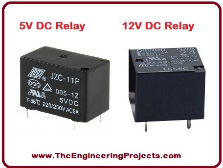
The phrase normal state always means the state shown in the datasheet with the coil de-energized. Energizing a standard changeover relay causes the common contact to leave the normally closed contact and touch the normally open contact. It does not turn an NO terminal into an NC terminal; the terminal names remain fixed.
Relay Terminals and Contact Names
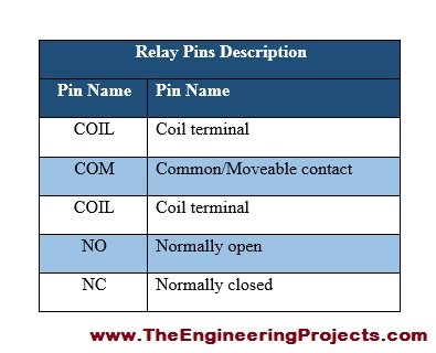
The familiar five-pin relay is commonly a single-pole double-throw, or SPDT, device. Two pins belong to the coil and three belong to one changeover contact set. Other relays may have four, six, eight or many more terminals, so never assume the pinout from the package shape alone.
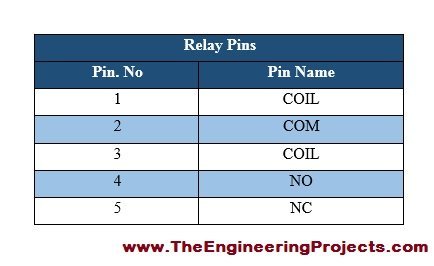
| Terminal | Meaning | State with coil off |
|---|---|---|
| Coil A and Coil B | Input terminals that energize the electromagnet | No coil current |
| COM | Moving or common contact | Connected to NC in a changeover relay |
| NC | Normally closed contact | Connected to COM |
| NO | Normally open contact | Disconnected from COM |
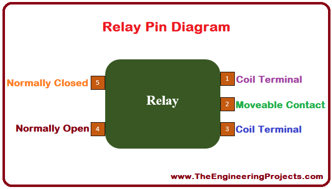
Use the manufacturer's datasheet to identify the terminals. If a loose, unmarked relay must be investigated, an ohmmeter can help: the coil usually has a measurable resistance that is independent of the contact terminals, and COM has continuity to NC while the coil is off. This test does not establish the allowable coil voltage or contact rating, so an unidentified relay should not be used for a safety-critical or mains-voltage design.
Inside an Electromechanical Relay
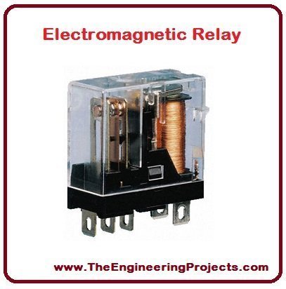
The main parts are the coil, iron core, yoke, movable armature, return spring and contacts. When current flows through the coil, the core becomes an electromagnet and attracts the armature. The armature transfers that motion to the contact spring. Contact material, spring force and travel are designed to provide low resistance when closed and sufficient separation when open.
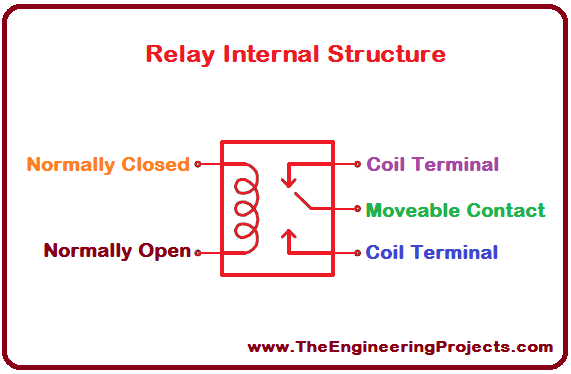
The coil is an inductive load. Its DC resistance limits the steady current, while its inductance opposes rapid changes in current. The contacts are a separate switching element and do not receive their load current through the coil. This separation is why a relay datasheet gives one group of coil specifications and another group of contact specifications.
Understanding the Relay Pinout
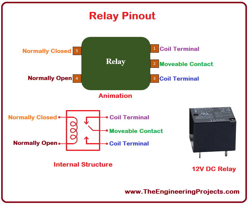
A pinout drawing is normally presented as a bottom view or terminal view. Check the viewing direction before wiring a printed circuit board because mirroring the footprint is a common mistake. Some DC relays include an internal diode or LED and are polarity-sensitive; reversing their coil leads can prevent operation or damage the driver. A plain coil without an internal suppression component is usually nonpolarized.
Contact symbols use poles and throws to describe the switching arrangement:
| Arrangement | Alternative contact form | Function |
|---|---|---|
| SPST-NO | Form A | One circuit closes when energized |
| SPST-NC | Form B | One circuit opens when energized |
| SPDT | Form C | One common terminal changes between NC and NO |
| DPDT | Two Form C sets | Two changeover circuits operate together |
Relay Working Principle
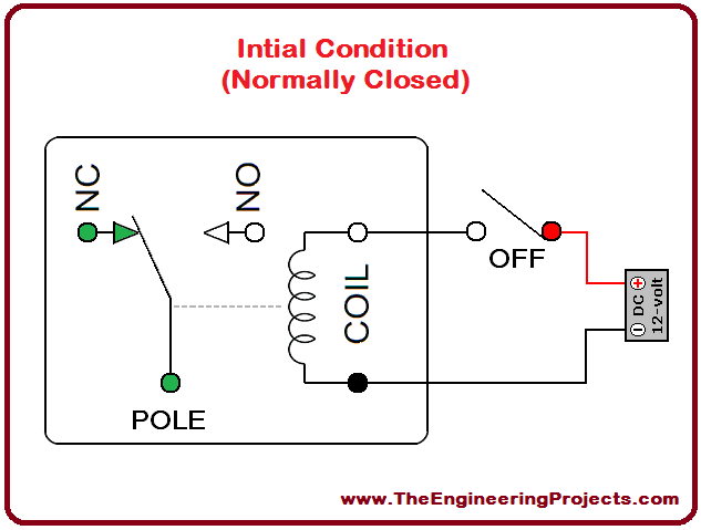
Consider a non-latching SPDT relay. With no voltage across the coil, the return spring holds the armature in its normal position. COM touches NC, while a physical air gap separates COM from NO.
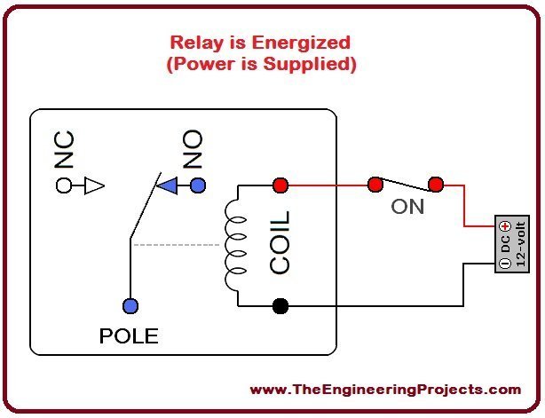
When the rated coil voltage is applied, coil current establishes magnetic flux in the core. The magnetic force overcomes the spring force and moves the armature. COM disconnects from NC and connects to NO. When coil power is removed, the collapsing magnetic field releases the armature and the spring restores the original state.
A practical relay does not change state instantaneously. Operate time, release time and contact bounce are specified in milliseconds. During bounce, the contacts may make and break several times before settling. This is usually acceptable for power switching, but a relay contact used as a digital input may require hardware or software debouncing.
Three Main Functions of a Relay
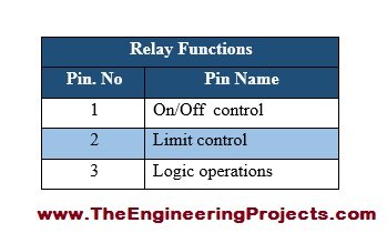
- Control: a low-power signal commands a separate load circuit.
- Isolation: properly rated coil and contact circuits can have no conductive connection between them.
- Contact multiplication or routing: one coil can operate several poles, or a changeover contact can select between two paths.
A relay does not create power or amplify energy in the electronic sense. The load energy comes from the load supply. The control circuit merely determines whether the contacts pass that energy.
Calculate Relay Coil Current and Power
For a DC coil, the datasheet may specify coil resistance, rated current or rated power. Ohm's law connects these values:
Icoil = Vcoil / Rcoil
Pcoil = Vcoil × Icoil = Vcoil² / Rcoil
Suppose a 12 V relay has a rated coil power of 400 mW. Its approximate current and resistance are:
Icoil = 0.400 W / 12 V = 0.0333 A = 33.3 mA
Rcoil = 12 V / 0.0333 A = 360 ohms
The actual resistance changes with temperature and has a manufacturing tolerance. Use the datasheet values over the required temperature range rather than treating this simple calculation as a guaranteed worst-case result.
A relay also has must-operate, must-release and maximum-allowable coil voltages. The rated coil voltage is the normal design value. Must-operate voltage is a guaranteed threshold, not a recommended continuous supply. The maximum allowable voltage may depend on ambient temperature and duty, and it should not be confused with a continuous rated voltage. Omron's general-purpose relay terminology explains these coil quantities in detail.
Relay Contact Ratings
Contact voltage and current must both remain within the datasheet limits, but choosing a relay is not as simple as multiplying those values to obtain watts. Manufacturers normally rate contacts for particular load types and may publish different limits for AC, DC, motors, lamps and small signals.
A resistive heater has little starting surge. An incandescent lamp can draw a large cold-filament inrush current. A motor can draw several times its running current at startup and creates an inductive transient when switched off. A capacitor-input power supply can also produce a sharp charging surge. These loads may require substantial derating or a relay with an appropriate motor, lamp or inrush rating.
| Specification | What it describes | Design question |
|---|---|---|
| Maximum switching voltage | Voltage the contacts are designed to interrupt | Is the load AC or DC, and what transients occur? |
| Rated contact current | Allowed current for a stated load category | What are the continuous and inrush currents? |
| Electrical endurance | Expected operations at a stated electrical load | How frequently will the load switch? |
| Mechanical endurance | Operations with little or no contact load | Do not substitute this for electrical life |
| Contact resistance | Resistance of a closed contact | Is loss acceptable at the intended current? |
| Minimum load | Lower region for reliable contact conduction | Is this a dry-circuit or sensor signal? |
| Isolation and spacing | Dielectric strength, creepage and clearance | Does the complete assembly meet its safety standard? |
Omron's Fundamentals of Relays notes that contact ratings vary with voltage and load type. Always select from the specific relay datasheet and allow margin for the real application.
Major Types of Relays
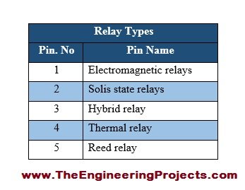
Electromagnetic Relay
An electromagnetic relay uses a coil, magnetic structure and mechanical contacts. It provides a clear open contact, can switch AC or DC within its ratings and is available with many contact forms. Its limitations include finite contact life, audible operation, bounce, coil power and a switching rate that is slow compared with semiconductor devices.
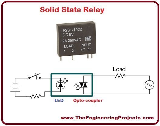
Solid-State Relay
A solid-state relay, or SSR, replaces moving contacts with semiconductor switching. An optical, capacitive or transformer coupling system may isolate its input from its output. SSRs switch silently, resist mechanical wear and can operate rapidly, but they have on-state voltage drop, leakage current when off and heat dissipation requirements. AC-output and DC-output SSRs are not interchangeable.
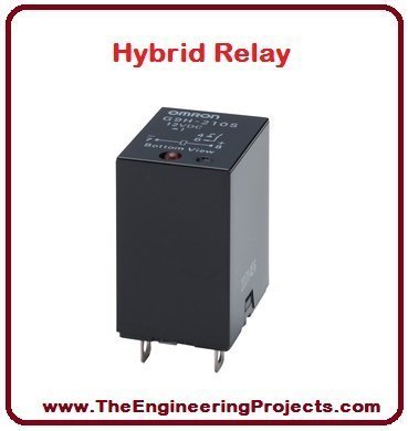
Hybrid Relay
A hybrid arrangement combines semiconductor control with mechanical contacts. One design may use electronics to manage coil power or suppress contact arcing; another may let a semiconductor handle switching transitions while a contact carries steady current with low loss. The exact behavior depends on the product, so the term hybrid alone is not a complete specification.
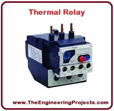
Thermal Overload Relay
A thermal overload relay protects a motor by responding to heating associated with sustained overcurrent. Traditional units use bimetal elements. They are designed to work with a contactor and provide overload protection; they are not a substitute for short-circuit protection. Trip class, reset method, motor current and ambient compensation must match the installation.
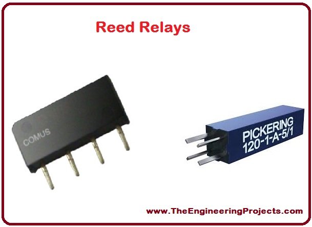
Reed Relay
A reed relay contains ferromagnetic contact blades sealed inside a glass capsule. A surrounding coil creates the magnetic field that brings the reeds together or changes their state. Reed relays are useful for small signals, low leakage and fast operation, although their contact power is generally lower than that of larger power relays.
Latching and Protective Relays
A latching relay retains its commanded state without continuous coil power and uses a pulse or polarity change to set or reset it. Protective relays monitor quantities such as current, voltage, frequency or phase and command a circuit breaker when a defined fault condition occurs. These functions differ from a basic PCB power relay even though all are called relays.
Drive a Relay from a Microcontroller
A microcontroller pin should not drive a typical relay coil directly. The coil may require more current than the pin can supply, and the coil releases stored magnetic energy when switched off. Use a transistor or a dedicated relay driver between the controller and the coil.
A common DC low-side driver contains:
- An N-channel logic-level MOSFET or an NPN transistor sized for the coil current.
- A flyback diode connected across the coil, reverse-biased while the relay is on.
- A suitable gate resistor and pull-down for a MOSFET, or a calculated base resistor for an NPN transistor.
- A supply that matches the rated coil voltage and can provide the starting and steady coil current.
- Common signal and driver grounds when the driver is not isolated.
The energy stored in a coil immediately before switch-off is approximately:
E = 1/2 × L × I²
Current through an inductor cannot stop instantly. Without a controlled path, the coil can produce a high voltage that damages the transistor or disturbs nearby electronics. The flyback diode carries the decaying current and clamps the voltage. Texas Instruments demonstrates this inductive transient and the need for protection in its relay-driver design procedure.
A simple diode also slows the decay of coil current and therefore delays contact release. When release speed matters, use a properly designed Zener, TVS or active clamp after checking the driver's voltage rating. Do not omit suppression merely to obtain faster release.
Relay Applications
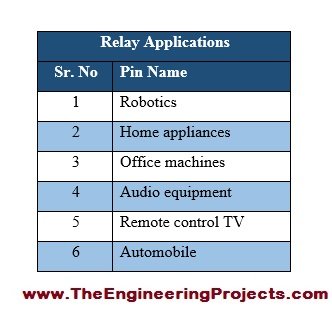
- Switching lamps, heaters, valves, pumps and fans.
- Selecting test points in measurement equipment.
- Providing dry-contact outputs from controllers and alarm systems.
- Changing motor polarity or selecting windings with interlocked contacts.
- Separating a control circuit from a differently referenced load circuit.
- Implementing overload, undervoltage and other protection functions with specialized relays.
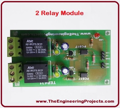
A relay module may contain one or several relays plus driver transistors, indicators and coil suppression. The label on the module does not guarantee complete isolation. If the board shares ground between its logic and coil driver, or if PCB spacing is inadequate for the load voltage, the system is not isolated in the way a bare relay symbol might suggest.
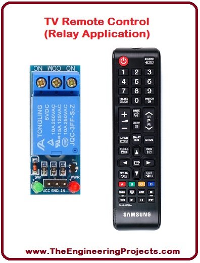
A remote-control receiver can command a relay to switch a television, lamp or other appliance. The handheld remote itself usually transmits an infrared or radio signal and does not need a power relay. The receiving control unit interprets the command and energizes the appropriate relay or semiconductor switch.
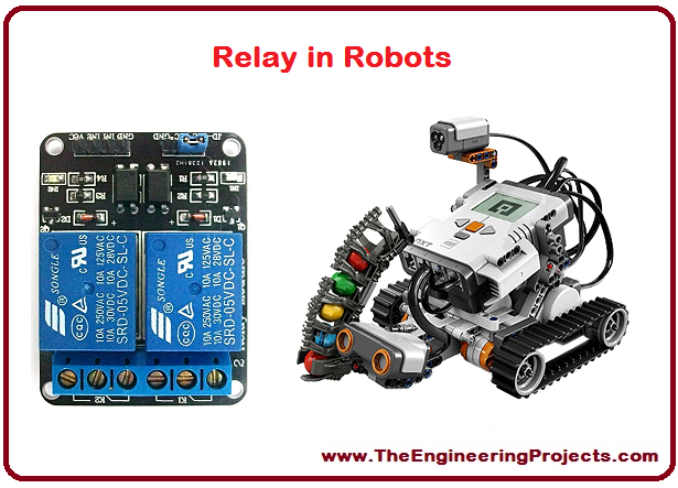
Robots may use relays for auxiliary loads, safety interlocks or simple motor direction control. An H-bridge is usually better when a DC motor needs frequent, fast or pulse-width-modulated control because mechanical contacts have limited life and switching speed.
Relay Simulation in Proteus
A simulation is useful for learning the relationship between the coil and contacts. Place an SPDT relay, a compatible coil supply, an input switch or driver, and an LED load with its series resistor. The contact circuit should have its own suitable source.
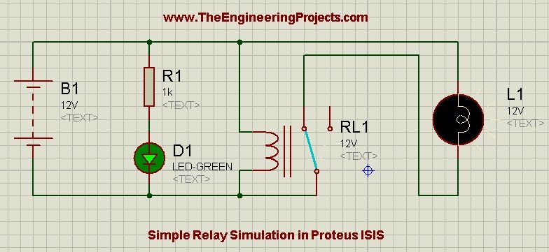
- Run the simulation with the coil off and observe which path COM follows.
- Energize the coil and confirm that COM transfers from NC to NO.
- Measure coil current and compare it with the value calculated from the model resistance.
- Move the load between NO and NC to see how the required default state changes.
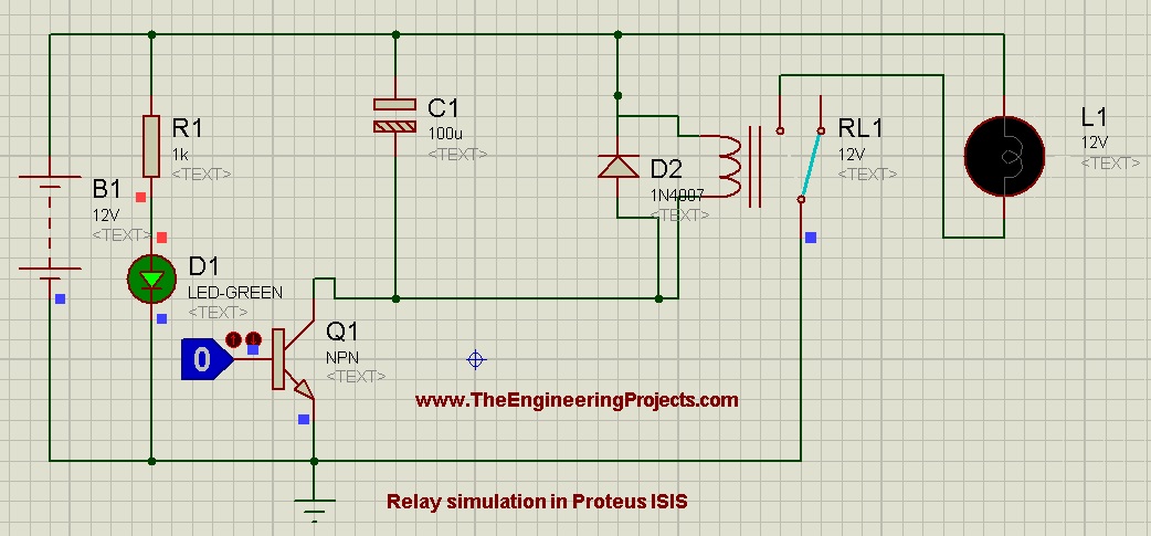
The related relay simulation in Proteus provides a focused simulation example. Remember that an idealized model may not reproduce contact bounce, arcing, thermal rise, insulation limitations or electrical life. A simulation supports circuit understanding; the component datasheet controls the physical design.
How to Select a Relay
- Define the load voltage, normal current, inrush current and whether the load is resistive, inductive, motor, lamp or capacitive.
- Select the required contact arrangement and the desired state when control power is absent.
- Check the manufacturer's contact rating for that voltage and load category, including electrical endurance.
- Choose a coil voltage available in the system and calculate its current and power.
- Verify operate voltage at the lowest supply voltage and highest expected coil temperature.
- Verify insulation, creepage, clearance, pollution degree and applicable safety approvals.
- Choose a driver and suppression network that tolerate the coil current and stored energy.
- Check ambient temperature, vibration, shock, mounting orientation and switching frequency.
Practical Safety Notes
Mains wiring can cause fatal shock, fire and equipment damage. A contact rating printed on a relay does not certify a homemade board or enclosure. The PCB layout, conductor width, creepage, clearance, fuse, connectors, enclosure, earthing and assembly method must all suit the intended voltage and applicable standards. Use an appropriately certified relay module or qualified design process when working with hazardous voltages.
Switch power off before changing wiring. Add a correctly rated fuse or protective device in the load circuit, keep low-voltage wiring separated from hazardous conductors and never touch a live circuit to investigate a relay that fails to operate.
Practical Review
An electromechanical relay uses coil current to create magnetic force and move isolated contacts. In a standard SPDT relay, COM connects to NC while the coil is off and transfers to NO while the coil is energized. Coil voltage and power determine the driver requirements, while contact voltage, current, load type and required life determine whether the relay can control the load.
The two sides must be designed independently and then checked together. A correctly rated contact does not make an unsuitable coil driver safe, and a correct coil voltage does not mean the contacts can interrupt any load. Reading the complete manufacturer datasheet is the final selection step.
Frequently Asked Questions
Are NO and NC defined when the relay is powered?
No. They are defined in the normal, de-energized state. With the coil off, COM connects to NC and remains separated from NO in a standard SPDT relay.
Can a microcontroller pin power a relay coil directly?
Usually it should not. Compare the coil current with the microcontroller's per-pin and total current limits. A transistor or relay-driver IC with suitable inductive suppression is the normal solution.
Why is a diode placed across a DC relay coil?
The diode provides a path for coil current when the driver turns off, limiting the inductive voltage spike. Install it with the correct polarity so it is reverse-biased during normal energization.
Can the same relay switch AC and DC at the printed current?
Do not assume so. DC arcs are harder to extinguish because the current has no natural zero crossing. Use the separate AC and DC ratings and the load category in the datasheet.
Does a relay module always isolate the microcontroller?
No. Isolation depends on the module circuit, power connections, optocoupler arrangement and physical spacing. Inspect its schematic and ratings instead of relying on the presence of a relay or optocoupler alone.
What is contact bounce?
Mechanical contacts can strike and separate several times before settling. The resulting short pulses may need debouncing when the contact feeds a digital counter or logic input.
When should I choose a solid-state relay?
An SSR is useful for silent or frequent switching and has no mechanical contact wear. You must still account for output type, off-state leakage, on-state loss, heat sinking and failure behavior.
Why does a relay become hot?
The coil continuously dissipates power while energized, and loaded contacts also generate heat. Excess coil voltage, high ambient temperature, excessive contact current, loose connections or frequent switching can raise temperature beyond the design limit.
This foundation prepares us for the next practical topic, where we will interface relays with a microcontroller through a ULN2003A driver.