How to Control Relay in Proteus ISIS


In today's post, we will first simulate the Relay in a simple circuit in which when you run the simulation, the relay will automatically got activated and after that we will go in a bit detail and will control relay using a logic, i.e. when you provide +5V to it then the relay will go activated and when you give GNd then it will de-energize. I will explain it below in detail how to use it with Microcontroller. Moreover, if you are planning to work on Relay then you should also check What is a Relay and How to use it? and should also have a look at Relay Interfacing with Microcontroller using ULN2003 and finally must check this one as well Relay Control using 555 timer in Proteus ISIS.If you have any questions. related to it then ask in comments and I will try my best to reply your queries. Let's get started with designing of control relay in Proteus ISIS.
Simple Control Relay Circuit in Proteus ISIS
- First of all, we are gonna simulate a simple control relay circuit in which we will manually turn on or off the relay.
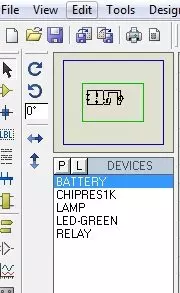
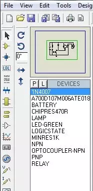
- Open Proteus ISIS and select the below components, as shown in below figure, from the components library of Proteus, if you don't know how to do it then check our earlier posts on Proteus.
- Now, design a circuit as shown in below figure:
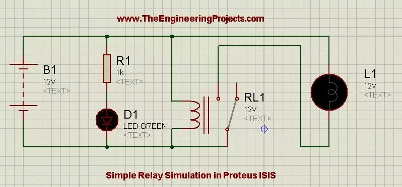
- The circuit is self explanatory, first we have used a simple 12V battery to power up the simulation, after that there's a small led attached, which will indicate that whether proper power is supplied to the system or not. Next is our relay, which is named as RL1 in the above figure.
- After the relay, we have placed a simple 12V lamp, so now when the relay will be energized, this lamp will glow up and when the relay is de-energized, the lamp will remain off. As in the above figure, the simulation is off, that's why the lamp isn't glowing.
- After designing the circuit, now click on the run button and if everything goes fine, then the lamp will glow as shown in below figure:
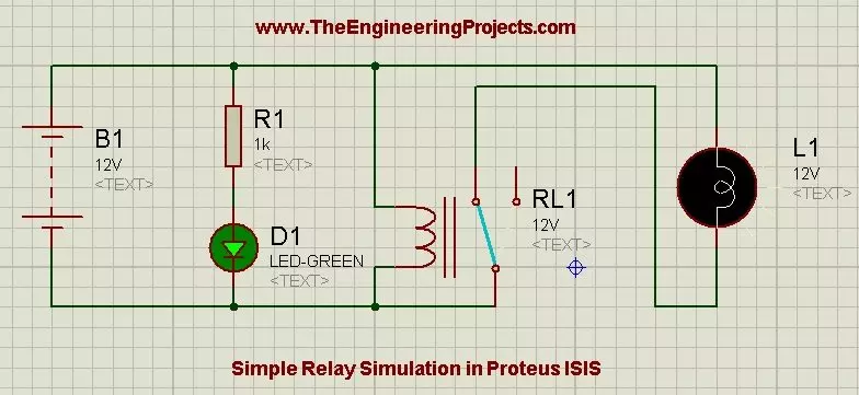
- So, now you can see the small led is also ON, I have used green that's why its showing green color indicating that power supply is working.
- If you compare the off state and on state simulation then you will see that the Relay is now connected with second terminal and thus completing the circuit for lamp and lamp is also now glowing.
Complex Relay simulation in Proteus ISIS
- Now, we are gonna design a bit more complex control relay simulation in Proteus ISIS, it's not much complicated but needs a bit more care while simulating.
- In previous section, we have seen a simple circuit which is operated manually means in order to turn it on or off you have to turn on or off the power supply but normally, it is required that the relay must be controlled by some microcontroller automatically.
- As the microcontrollers normally work on 5V so in order to control a 12V relay using 5V microcontroller, we need to use transistor. In that case, when you give +5V the relay got actuated and when you give GND then relay get turned off.
- So, first of all get these components from the Arduino components library.
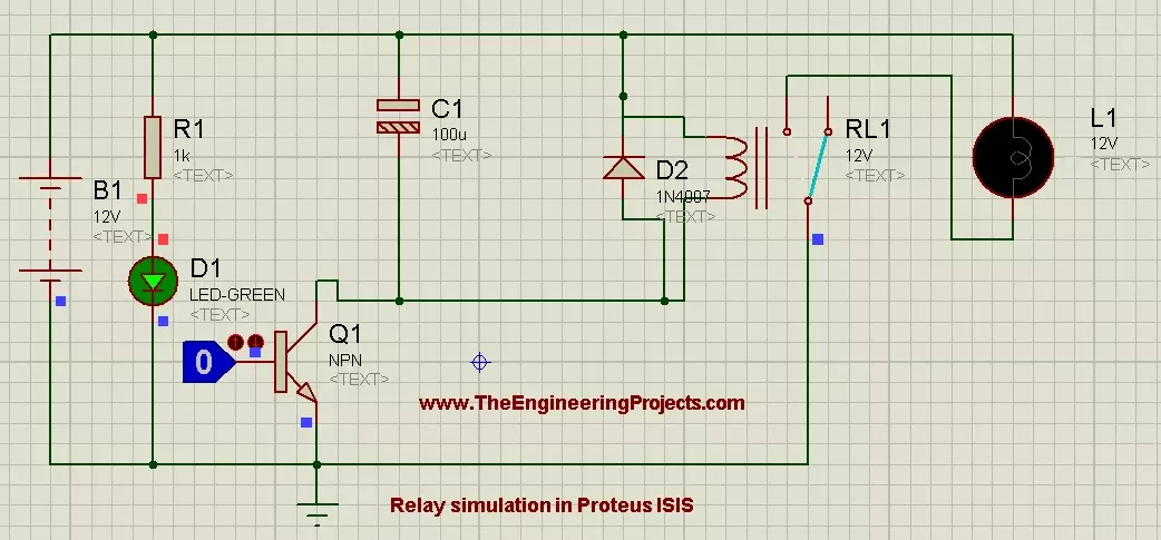
- Now, design the circuit as shown in the below figure:
- As this tutorial is about relays so I haven't used microcontroller here, instead I used this logic state, it will work same as microcontroller. So the above circuit is quite similar to the simple circuit we have seen in the above section. The only difference here is the NPN transistor.
- Now, we are not providing the supply directly to the relay, instead we are providing it via this transistor. So, when the logid state is zero means ground, the transistor won't work and the supply cant reached to the relay and when we make the logic 1 means +5V on the base of transostor, then the relay circuit will complete and the relay will be energized.
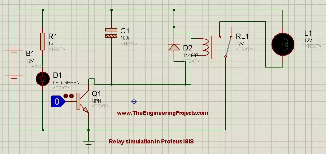
- Now run the simulation, the off state is shown below:
- In the above figure, you can see that the led goes on because the power is supplied to the circuit but the lamp is still OFF and the relay is also not energized because the logic state is a low level i.e. 0.
- Now click on the logic state to make it on high level i.e. +5V, the on state is shown in below figure:
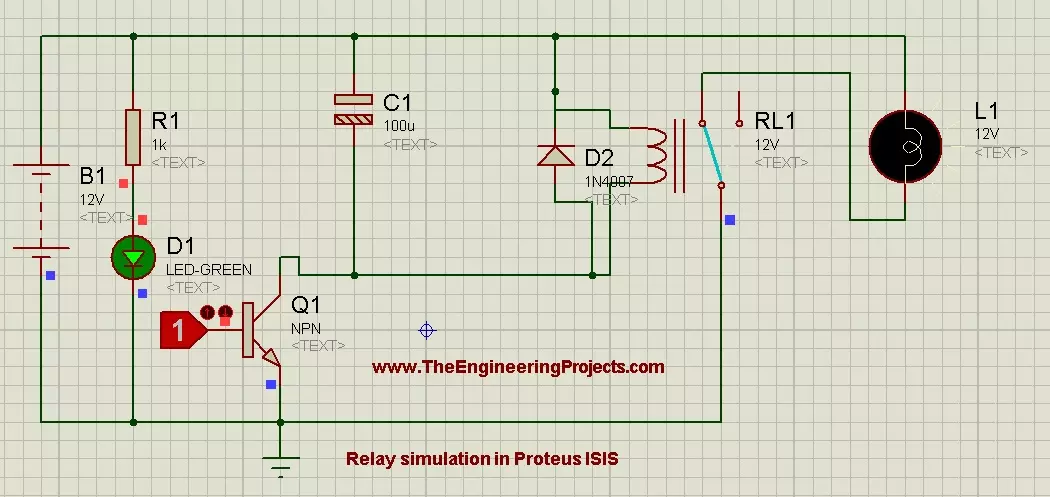
- Now you can see that as we make the logic state high, now relay got connected and the lamp is also ON. So by comparing both ON and OFF states, you can easily get the idea how the relay is operating.
- If you are planning on using the relay with microcontroller, then simply remove this logic state and connect the base of transistor with the output pin of microcontroller and when you low the microcontroller pin relay will get de energized and and when you make the pin high, it will get energized.
- That's all for today, hope you have got something out of it. In the next post I will show how to simulate a DC motor using relay. Till then take care. :))