


Common Base BJT Amplifier in Proteus


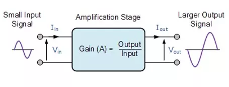
What is Common Base BJT Amplifier?
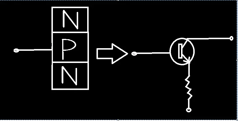
The precise definition of the Common Base BJT Amplifier is: "The type of Bipolar Junction Transistor Amplifiers in which Base is Common to both emitter and Collector and Current gain is taken from the Base is called Common Base bipolar Junction Transistor Amplifiers." Recall that a transistor has three regions i.e, Base, Collector and Emitter. Hence we design our Circuit in such a way that we get the output of current from the base and get the best current gain.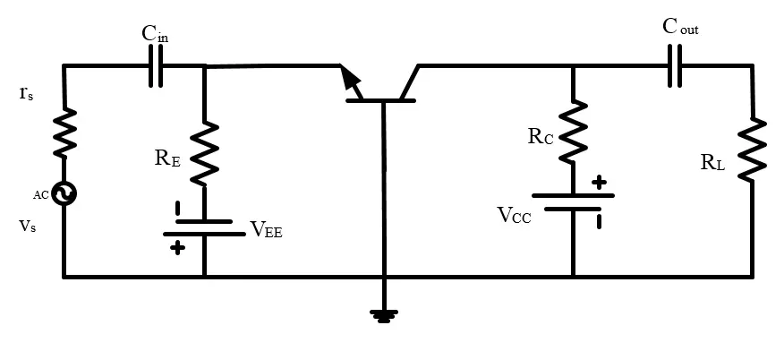
Basic Concepts:
Some Important Concepts should be kept in mind so that it will become easy and interesting to Design the Circuit. Current gain: " The Current gain of Common base Amplifier is equal to the ratio of Current in the Collector to the Current in the Base provided by the constant voltage of base to collector." Mathematically,Current gain=Collector Current/Base Current
ß=Ic/Ib
Voltage Gain: "The Voltage gain of the Common Base amplifier is obtain when we divide the Voltage of Collector to the voltage of emitter." mathematically,Voltage Gain=Voltage of Collector/Voltage of Emitter
Av=Vc/Ve
Implementing Common Base BJT Amplifier in Proteus ISIS
To Perform the experiment. we need the Proteus ISIS then follow the steps: Material Require:- Transistor (2N1711)
- Capacitor
- Alternating Current Source (Vsine)
- Resistor
- Oscilloscope
- Ground.
- Open Your Proteus software in the PC.
- Seek the Pick Library "P" button and write the name of 1st four Components one by one and select them.
- Place the current components on the working area.
- Acquire the Oscilloscope from the "Virtual Instruments mode" from the left most area and fix it just above the circuit.
- You can obtain the Ground Terminal by left click on the screen>Place>Terminal>Ground or just search it in the "Terminal mode".
- Connect all the Components through wires. The circuit looks like the image given below:
- At this instance , Change the name and values of resistors one by one by double clicking them. In this way, the circuit will work Perfectly.
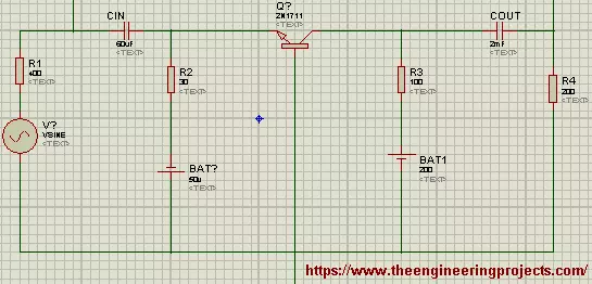
- I labelled all the Resistors with different names and changed the values according to the need.
- At the same token, the name of Capacitor, battery cells and their values are also changed according to the table given below:
| Components | Values |
| Resistor R1 | 400ohm |
| Resistor R2 | 30ohm |
| Resistor R3 | 100ohm |
| Resistor R4 | 200ohm |
| BAT | 50 |
| BAT 1 | 200 |
| CIN | 2mF |
| COUT | 60uF |
| Oscilloscope | Channel A=20V, Channel B=20V, time=0.5m-1 |
| VSine | Amplitude 220V, Frequency=1000 |
- Set all the values according to table.
- Once the values are selected (except Oscilloscope) just Pop the Play button.
- You can see an Oscilloscope screen showing the waves.
- Turn of the Channel C,D to avoid distraction.
- Set the values of Oscilloscope by matching with the table.
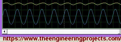
- You will get the output just like shown in the following image:
- Connect the DC Ammeter from the "Generation Mode" and Connect one with the Base of transistor and one with the Collector.
- When we play the Simulation then we get the following Output:
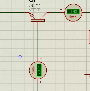
ß =-1.43/-0.07
=20.4
As it's a ratio so it doesn't have any unit. Moving towards the Voltage Gain,- Take the "DC Voltmeter" from the same Portion and connect one Voltmeter with CIN capacitor and one with the COUT Capacitor. Note than the Voltmeter is always Connected in parallel to the required Components.
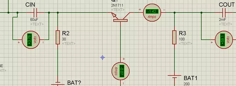
Av=53.1/3.75
=14.16
So that the required Quantities are obtained.Characteristics of Common Base BJT Amplifiers:
- It has High Voltage Gain.
- The Current Gain of Common Base BJT Amplifiers is Medium.
- We get High power Gain in this type of Amplifier.
- Common Base Amplifier does not have any reversal effect between input and output waves.
- The Input and Output resistance of the Common Base Amplifier is Medium.
Advantages:
- We Get the inverted output wave that may be useful in many electronic devices.
- The Input Impedance is Low.
- It is useful due to its high power gain.
- The output Impedance is High for Common Base Bipolar Junction Transistor Amplifiers.
- The Output Impedance is high.
- When we need Impedance matching then CB Amplifiers are useful because we can control the input Impedance.
- It Provides the constant Current Gain therefore can be used as buffer amplifiers.
×
![]()


