


Stepper Motor Drive Circuit in Proteus ISIS


Hello friends! In the previous tutorial, we controlled the direction of a DC motor in Proteus. Now we will work with a stepper motor, where rotation depends on applying an ordered sequence to the windings. We will begin with the original six-wire simulation, inspect the sequence manually, and then explain how a microcontroller and driver can generate it.
The original screenshots use Logic State sources to make individual winding states visible. They are useful for understanding the sequence, but they are not a physical driver circuit. We will preserve the images and add the missing distinction between simulated logic sources, microcontroller outputs, and the winding-current path.
By the end, you should understand unipolar and bipolar wiring, wave drive and half stepping, direction reversal, and the relationship between step frequency and shaft speed. We will also add a small PIC16F877A example that continues the controller used in the preceding tutorial.
How a Stepper Motor Moves
A stepper motor has windings arranged so that different excitation states create different magnetic-field orientations. The rotor tends to align with the resulting field. Advancing through a suitable sequence moves that field and produces successive mechanical steps.
The sequence order matters as much as the logic levels. Energizing windings in an arbitrary order can make the rotor vibrate, reverse unexpectedly, or remain near one position. Correct sequencing is the first thing to establish before increasing the update rate.
A commanded step is not proof that the rotor completed the corresponding motion. With excessive load or acceleration, an open-loop motor can miss steps. The program may continue counting commands even while the physical position falls behind. This is why a stepper application still needs a realistic torque and motion plan.
Unipolar and Bipolar Windings
A common four-wire stepper has two windings without accessible centre taps and is driven by reversing current through each winding. A six-wire arrangement exposes the centre tap of each of two windings. That permits unipolar operation by selecting one half winding at a time.
Wire count is a useful clue, not a complete wiring specification. Five-wire and eight-wire arrangements also exist, and connector colours are not a universal standard. Use the motor's datasheet or identify its winding continuity with the motor disconnected from power.
| Arrangement | Typical connection concept | Driver implication |
|---|---|---|
| Four wires | Two separate windings | Usually requires bidirectional current in each winding |
| Six wires | Two windings with separate centre taps | Can use a suitable unipolar drive arrangement |
| Five wires | A common connection shared by winding sections | Verify the internal connection before selecting the driver |
| Eight wires | Separately accessible winding sections | Allows connection options specified by the manufacturer |
This tutorial concentrates on the six-wire conceptual model shown in the original article. Do not apply its centre-tap instructions to a four-wire bipolar motor. A ULN2003A current-sinking array alone cannot reverse current through a complete bipolar winding.
Build the Original Manual Simulation
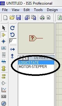
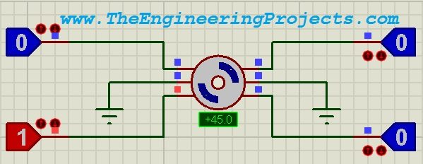
Select the stepper model and Logic State sources shown in the original component screenshot. Place the motor where you can see its terminal connections and displayed position. Begin with slow manual changes so that each excitation state can be inspected.
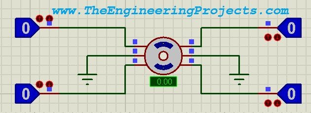
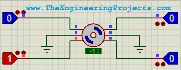
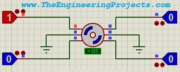
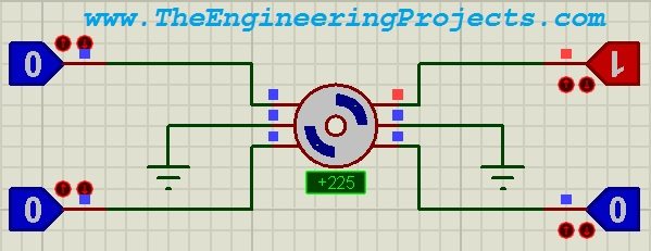
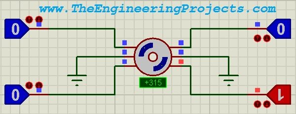
The original circuit uses four controllable winding-end connections and two common connections. Its common points are shown tied to ground, with idealized logic sources applying the other levels. That is a teaching arrangement for the simulation model. The practical sinking-driver arrangement described later uses positive centre taps and switched current paths to ground instead.
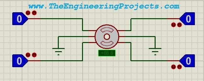
Keep those two arrangements distinct. Moving from one to the other changes how current is established in each half winding. Do not add a ULN2003A to the old image while leaving every other connection unchanged and expect it to create the intended current path.
Define the Electrical Phase Order
For the following explanation, call the two ends of the first centre-tapped winding A1 and A2, and the corresponding ends of the second winding B1 and B2. One useful excitation order is A1, B1, A2, B2, provided those names have been assigned to the actual motor consistently.
These labels describe our chosen sequence, not a promise about the position of terminals on every symbol or connector. Map the model's pins to the winding names before testing. If the rotor only rocks between positions, check that mapping rather than increasing the delay until the vibration looks slower.
Wave Drive: One Half Winding Active
| State | A1 | B1 | A2 | B2 |
|---|---|---|---|---|
| 1 | ON | OFF | OFF | OFF |
| 2 | OFF | ON | OFF | OFF |
| 3 | OFF | OFF | ON | OFF |
| 4 | OFF | OFF | OFF | ON |
Repeat states 1 through 4 to continue rotating. Reverse their order to reverse the requested direction. The direction named clockwise still depends on the motor orientation and winding labels, so record which sequence produces the desired physical direction in your setup.
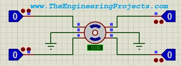
The original image sequence below shows the motor responding as the excitation state changes. Its displayed angles belong to that demonstration model; use the actual model or motor specification when calculating steps per revolution.
Two-Phase Drive and Half Stepping
A two-phase-on sequence energizes adjacent phase states together. Half stepping alternates single-phase and adjacent two-phase states, inserting intermediate field orientations. In our A1, B1, A2, B2 ordering, an illustrative half-step sequence is:
1000, 1100, 0100, 0110, 0010, 0011, 0001, 1001
Here, each printed digit refers to one named phase in that left-to-right order, and 1 means energized. This notation is not automatically the same bit order as a numeric byte written to a microcontroller port. Define the mapping explicitly when converting the table into code.
Half stepping increases the number of commanded positions per revolution relative to the corresponding full-step sequence, but it does not make the system immune to missed steps. A simple fixed-current pattern can also produce different torque between one-phase and two-phase states. Microstepping requires controlled phase currents and is not achieved merely by shortening delays between digital states.
Calculate Step Angle, Speed, and Travel
For a motor with a full-step angle of α degrees, the number of full steps per revolution is N = 360 / α. A hypothetical 1.8-degree motor therefore needs 200 full steps for one revolution. Do not assume the original simulation model has that angle unless its properties say so.
The speed relationship is rpm = 60 × step frequency / steps per revolution. At 100 full steps per second with a 200-step motor, the commanded speed is 60 × 100 / 200 = 30 rpm.
If half stepping requires 400 updates per revolution, the same 100 updates per second corresponds to 15 rpm. Increasing position resolution without increasing the update rate therefore reduces the commanded rotational speed. Keep “steps” and “sequence updates” clearly defined in your calculations.
For an ideal leadscrew with 2 mm travel per revolution and 200 full steps per revolution, one full step corresponds to 2 / 200 = 0.01 mm of nominal travel. Backlash, compliance, missed steps, and manufacturing tolerances mean that commanded increment is not the same thing as guaranteed positioning accuracy.
Use a Driver for Physical Windings
For a suitable unipolar motor, a ULN2003A provides multiple current-sinking channels between logic signals and winding ends. The microcontroller drives the array's inputs; the array switches winding current. The motor's centre taps connect to the appropriate positive winding supply.
The Texas Instruments ULN2003A datasheet identifies the common emitter and the clamp-diode COM connection. COM is not the logic ground pin. For this inductive-load arrangement, connect it to the winding supply as specified so that the internal clamp diodes have the intended return path.
| Connection | Destination | Purpose |
|---|---|---|
| PIC RB0, RB1, RB2, RB3 | Inputs 1B through 4B, pins 1–4 | Sequence-control signals |
| Outputs 1C through 4C, pins 16–13 | A1, B1, A2, B2 winding ends | Switched current paths |
| Motor centre taps | Positive winding supply | Common supply for the selected half windings |
| ULN2003A E, pin 8 | Common ground | Current return |
| ULN2003A COM, pin 9 | Positive winding supply | Inductive clamp-diode return |
Check the motor current, driver voltage drop, package dissipation, and combined channel loading. The array does not regulate winding current. A low-resistance motor intended for a current-regulated driver may require a different solution rather than being connected directly to an arbitrary supply through this array.
Generate the Sequence with a PIC Microcontroller
Once the manual sequence is clear, we can generate it in firmware. In this example, RB0, RB1, RB2, and RB3 of a PIC16F877A drive the four ULN2003A inputs in the order given above. The motor connects to the driver outputs, not directly to the PIC. Keep the driver ground and PIC ground connected so the input voltages have a common reference.
The following mikroC example uses wave drive: exactly one winding channel is active at a time. Create a PIC16F877A project, select an 8 MHz clock, and give the simulated PIC the same clock frequency. Configure the oscillator for the actual clock arrangement, disable the watchdog for this simple blocking demonstration, and disable low-voltage programming because RB3 is being used as a sequence output. Consult the PIC16F87XA datasheet for the device configuration and pin functions.
const unsigned char wave[4] = {0x01, 0x02, 0x04, 0x08};
unsigned char stepIndex;

void main() {
    PORTB = 0;
    TRISB = 0;
    while (1) {
        for (stepIndex = 0; stepIndex < 4; stepIndex++) {
            PORTB = wave[stepIndex];
            Delay_ms(10);
        }
    }
}
The numeric value 0x01 makes RB0 high, 0x02 makes RB1 high, and so on. This is why the table's left-to-right winding notation must not be copied blindly as a binary number: the lowest numbered output is the least significant bit in this code. Match electrical channels to named winding ends before interpreting rotation direction.
With 10 ms between state changes, the nominal stepping rate is approximately 100 steps per second, with a small additional contribution from instruction overhead. The 30 rpm calculation above applies only to a motor that actually has 200 full steps per revolution. Use the step angle configured in your simulation model, or the physical motor's specification, to calculate its speed.
For opposite rotation, reverse the sequence to {0x08, 0x04, 0x02, 0x01}. A more complete program maintains the current phase index and increments or decrements it according to the requested direction. That avoids jumping arbitrarily to a new phase whenever a direction button is pressed. For this first exercise, stop the simulation before changing the array and reload the newly compiled HEX file.
Holding Position and Releasing the Motor
Stopping the sequence while leaving the last channel energized produces holding torque. Clearing all four outputs releases electrical holding torque, although mechanical detent torque may remain. These are different stop behaviours. Decide which your mechanism needs: a lightly loaded pointer may be allowed to relax, while a vertical load may move if you remove current.
Holding also dissipates power continuously. For an illustrative 50 ohm half winding driven from 5 V with a 0.9 V driver drop, the steady current is approximately I = (5 - 0.9) / 50 = 0.082 A. Winding dissipation is then P = I²R = 0.082² × 50 = 0.336 W. These assumed values demonstrate the calculation; measure or obtain the real winding resistance and driver characteristics before choosing a supply.
Two simultaneously energized half windings would dissipate about twice that winding power under the same assumptions, plus losses in the driver. Inductance means the current takes time to rise after each switching event, so a steady-state calculation alone cannot predict torque at high stepping rates.
Run the Simulation and Check One Change at a Time
- Start with the manual Logic State circuit and verify the winding order at a slow pace.
- Build the driver stage separately and confirm that one asserted input selects the intended winding channel.
- Load the PIC HEX file, match its clock setting, and run the four-state sequence.
- Observe several complete electrical cycles before increasing the stepping rate.
- Reverse the order, keeping all wiring unchanged, and check that the rotation reverses.
- Compare the configured step angle, commanded step count, and displayed movement.
Do not begin by reducing the delay to its smallest possible value. Real motors have limited pull-in speed and acceleration. A rotor that starts correctly at a low rate may miss steps if asked to jump instantly to a much higher rate, particularly when driving a load. An acceleration ramp gradually reduces the interval as the motor gains speed; a deceleration ramp does the reverse before stopping.
For positioning, count commanded transitions rather than loop iterations. This example issues four transitions per complete pass through the array. At startup, the first energized phase can align an initially unknown rotor, so that initial movement should not be treated as a known displacement. A home switch or another reference establishes a repeatable starting position when absolute travel matters.
Troubleshooting the Stepper Circuit
| Symptom | What to examine |
|---|---|
| Rotor vibrates without rotating | Check the winding pairs and phase order; alternating unrelated states can cancel useful movement. |
| Rotation works in the wrong direction | Reverse the sequence and document your viewing direction; clockwise depends on the side from which you observe the shaft. |
| Motor starts slowly but stalls at a higher rate | Reduce the initial step rate, add acceleration, and check available torque under load. |
| One phase never activates | Inspect its logic signal, driver input, winding connection, and PIC pin configuration, including RB3 low-voltage programming. |
| Driver becomes hot | Calculate channel current and total package dissipation; check the motor's winding rating and supply voltage. |
| Position changes after outputs are cleared | The program has removed holding torque; assess the mechanical load and required stop behaviour. |
When identifying an unpowered six-wire motor, a resistance measurement can help distinguish the two winding groups. Within a typical centre-tapped winding, resistance from the centre tap to either end is approximately half the end-to-end resistance. Verify the manufacturer's wiring information wherever available; wire colours are not a universal pinout.
Review of This Stepper Motor Demonstration
The manual circuit makes the phase sequence visible, while the PIC example shows how firmware repeats it. The driver discussion connects those logic states to a practical current path. Together, these stages explain direction, stepping rate, and nominal position without confusing a logic output with a winding power supply.
The simulation is useful for checking sequencing and basic program behaviour. Its result does not establish the torque margin, thermal performance, resonance, or positioning accuracy of a loaded physical mechanism. Those depend on the selected motor, driver, supply, mechanics, and operating conditions.
Frequently Asked Questions
Can I connect a stepper motor directly to PIC pins?
No. Use a driver matched to the winding arrangement and current requirements. The microcontroller supplies control signals; the driver handles winding current and inductive switching.
Can a four-wire bipolar motor use this exact ULN2003A circuit?
No. A bipolar winding needs current in both directions. Use an appropriate bipolar driver rather than the centre-tapped unipolar arrangement described here.
Does increasing the stepping rate always increase speed?
It increases commanded speed. Actual speed follows only while the motor can maintain synchronism. Above its available torque and acceleration limits, it can miss steps or stall.
Does half stepping double positioning accuracy?
It doubles the nominal number of commanded positions per revolution for the sequence described here. Mechanical accuracy still depends on the motor, load, driver, and transmission.
Why does the motor move when the first phase turns on?
The energized field attracts the rotor toward that phase's equilibrium position. Without homing or position feedback, the initial shaft position is not known precisely.
Now that you can follow a stepper's winding sequence, continue with servo motor control with a PIC microcontroller. There we will use a pulse-width command to request a position from a motor assembly that includes its own feedback controller.

brother will you help me in drawing a transfer curve for any transistor in ISIS as i am working on my mini project. I m from uet peshawar
Dear Syed,
I will need your servicees to write program and make project to control stepper motor via Enthranet connection.
Please let me know if you are available for such project
Best regards
Boris
1 reply
Yeah we can provide you the complete project. Add me on skype and we will discuss it. My Skype id is theenggprojects.
Thanks.
Comments
5