


Common Emitter BJT Amplifier in Proteus


- What are Common Emitter Bi-Junction Transistors.
- Concepts of Common Emitter Bi-Junction Transistors.
- Implementation of Common Emitter BJT Amplifiers in Proteus ISIS.
- Why we use Common Emitter BJT in Amplifiers.
What are Common Emitter Bi-Junction Transistors
There are three types of Configurations of a transistor named:- Common Emitter Configuration
- Common Base Configuration
- Common Collector Configuration
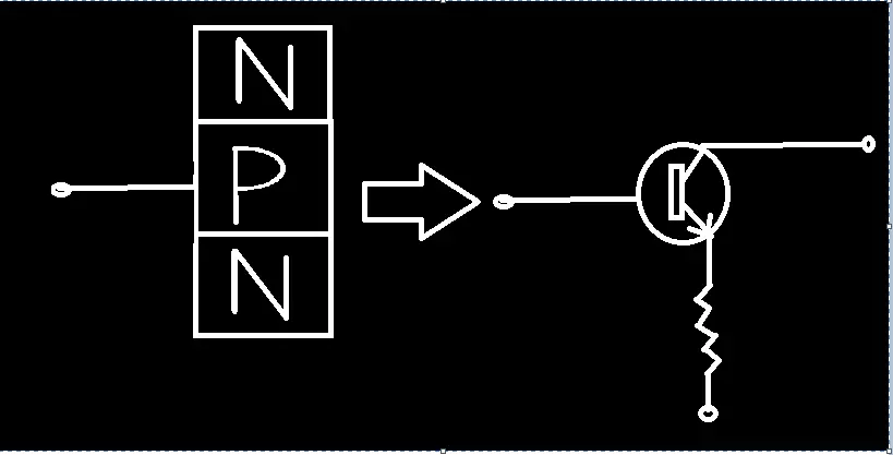
- NPN configuration.
- PNP Configuration.
Concepts of Common Emitter Bi-Junction Transistors
At this instance We'll look at some basic concepts, on the basis of which we chose these Components along with the values of Components of amplifier. Current gain: In BJT Amplifiers, current gain is the ratio of change in collector current to the change in the current of base.mathematically, Current Gain= Change in collector current/Change in Base Current
ß=?Ic/?Ib
At the same token, Voltage Gain: The Voltage Gain of an amplifier is the product two Quantities. One is the ratio of output resistance of the collector to the input resistor of the base, and the other is the current gain.Voltage Gain=ß(Rc/Rb)
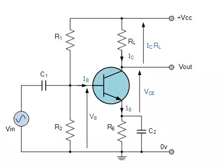
During the Practical work we take AC output voltage from collector with respect to emitter and the Output of Amplifier is taken from Collector. On the other hand, the input is given to the base terminal. It is obvious to notice that the emitter is Common to Base and Collector. It consist of Voltage divider biasing, hence one of the basic part of circuit is consist of two resistors so that their mid-point is used for supply Base Bias voltage. One more importance point to remember is gain is different from one transistor to the other.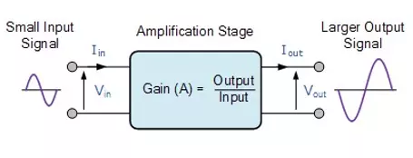
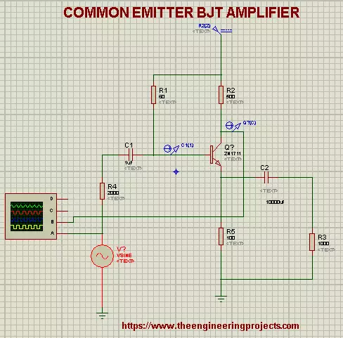
Implementation of Common Emitter BJT Amplifiers in Proteus ISIS
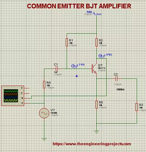
For the practical verification of the circuit It is always Advisable to Perform it at any simulation software. Hence open Your Proteus ISIS. Components Required:- NPN transistor (2N171) .
- Vsine
- Capacitor
- Resistor
- DC Power source
- ground Terminal
- Oscilloscope
Procedure:
- Choose 1st four Components from the Pick Library "P" one by one by writing their name in it.
- Collect the DC power supply from "Generator mood" present on the left most tab.
- To get the Ground terminal, left Click on the working screen and go to Place>Terminal>Ground and fix it on the screen.
- Oscilloscope is present in the "Virtual Instrument Mood" on the same tab.
- Once you have chosen all the required Device then set them one by one on the Working area according to the Picture given below and connect them with the help of wires.
- At the Instance we will change the values of some devices So I have made a table for this:
-
Components Values Resistor R1 60ohm Resistor R2 500ohm Resistor R3 1000ohm Resistor R4 2000ohm Resistor R5 100ohm Oscilloscope A=20V, B=2V Vsine Frequency=1000Hz, Amplitude=110V DC source 10V
- Select the Current probe from the left most bar and connect them in the circuit one with the Base wire and the other with the collector.
here,
Current gain=6.2*10-12/6.1
=1.01*10-9
as it is a ratio, hence has no unit.At the same token,
Voltage gain=1.01*10-9*(500/2000)
=2.5*10-10
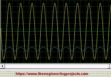
NOTE: The Gain is vary from transistor to transistor and the temperature is also an important feature. Therefore, the gain is always unpredictable.- We got the required output in the Proteus ISIS as required.
Why we use BJT in Amplifiers
Common Emitter BJT Amplifiers are important in the World of Electronics. One can get the idea of their influence by the following points:- These Amplifiers are used in low frequency voltage amplifier.
- The are useful because of their high power gain with medium voltage and current gain hence they are cheap.
- The output impedance is high.
- It has inverting effect so can be used in the different appliances for different purposes.
×
![]()


