Hello friends, I hope you all are doing great. In today's tutorial, we will simulate our First Electronics Project in Proteus ISIS. It's our 2nd tutorial in Proteus series. In our previous tutorial, we have seen a basic Introduction to Proteus and today, we will design a simple electronics circuit in it and will also simulate it.
If you want to work on Proteus, then you must have some prior knowledge about electronics. Proteus doesn't provide any suggestion about circuit designing so if you don't have electronics knowledge then you can't work with Proteus. Throughout this series, I will keep on explaining electronics circuits as well and will also embedded related components' links. So, if you are new to electronics then no need to worry and just follow these instructions and also do read those embedded links to understand electronic components. So, let's Create our First Project in Proteus:
Simulate First Electronics Project in Proteus ISIS
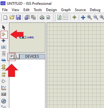
Open your Proteus ISIS software and then click on Components Mode in left menu tab, as shown in the figure.
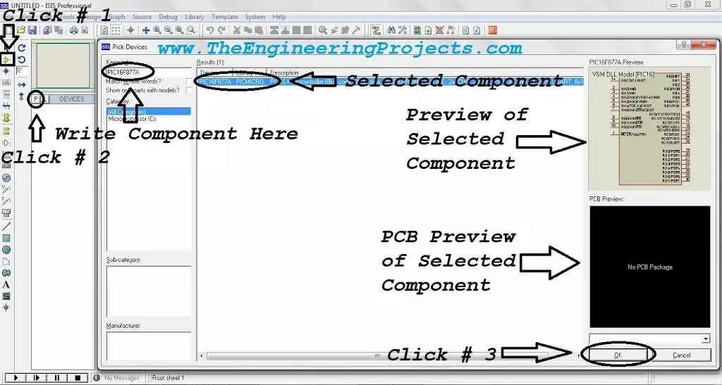
After that click on the P (Pick from Libraries) Button, and a new window will open up.
This new window is called Pick Devices and is used to make search for electronics components.
Proteus has a huge database of electronics components in the form of libraries. i.e. Diode Library will have all the diode components.
So, from these millions of components, we need to make a search for our required components to design electronic circuit.
You can see Pick Devices window in below figure, so let's first discuss its layout:
Keywords textbox is used to make a search for any component and Proteus will display the related components in Results panel. ( We will search in a while )
Category Section displays all the categories available in Proteus and when you click on any category then it's components will be displayed in Results panel.
After that, we have Sub-category & Manufacturer, rite now I don't have any.
On the right side we have Schematic Preview & PCB Review, so when we select any component then its respective Previews will be shown here.
So, now let's make a search for LED, as shown in below figure:
As you can see in above figure that Proteus has provided us with 141 Results and I have boxed four LEDs, which I am going to use in my circuit.
Moreover, Category section is now showing only those categories which are related to searched keyword.
Moreover, we also have a Schematic Preview but we don't have any PCB Preview as it's not available for this component.
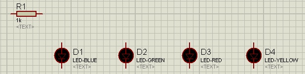
So, double click on these four LEDs and they will be added in Proteus workspace.
Moreover, we also need to add resistance so make a search for resistance, as shown in below figure:
Double click on this RES component and then close this Pick Devices window.
You will get these selected components in the Devices section, as shown in below figure:
As we are designing a simple project so we have selected just four components but in complex projects, we have a long list of components in this Devices section and it proves quite helpful.
So, let's place these components, one by one in the central work area.
You can drag & drop them OR can select by clicking and then again click to place.
I have placed these components in the work area, as shown in figure on right side.
So, now let's connect them together using wires and for that, we need to click on the pin terminal of each component.
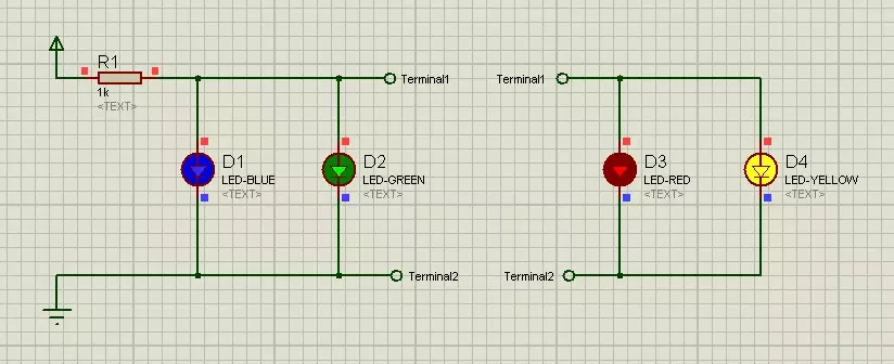
I have combined these electronic components together using wires, as shown in below figure:
Now we need to provide voltage supply to this circuit and there are several voltage sources in Proteus. ( We will cover them in coming lectures )
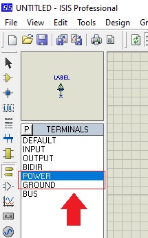
For now, let's click on the Terminals Mode in the left Toolbar and you will get Proteus Terminals, as shown in figure on right side.
From these terminals, we are going to use Power & Ground, so place them in the circuit, as shown in below figure:
We will discuss all these Terminal Components in detail in our coming lectures.
If we place multiple Ground components in the circuit then Proteus will consider them all as connected/short.
These Terminals are quite helpful, as in complex circuits, these wires can become too messy and we can avoid them by using these terminals.
So, we have completely designed our circuit but we need to change the properties of these components a little.
So, double click on resistance to open its Properties Panel, as shown in below figure:
From this Edit Component window, we can edit different properties of selected component.
As you can see, first we have Component Reference, that's the name of our component i.e. R1. If we have multiple resistances, then there names will be R2, R3 and so on.
We can't have multiple items with same Component Reference, as it will create an error.
Second Property defines the resistance of the component and I have changed it from 10k to 1k.
Then we have Model Type and its analog.
Finally we have PCB Package, we will use it when we will be designing the PCB design of this circuit.
So, click on the OK Button and resistance value will change from 10k to 1k.
Now, double click on first LED to open its Properties Panel, as shown in below figure:
As LED is a bit complex component as compared to resistance, that's why it has a lot more Properties to Edit.
As we are designing a digital circuit, so we need to change the Model Type of LED from Analog to Digital and then click on the OK Button.
You need to change this Model Type for all these four LEDs.
So, now we have completely designed our first electronic circuit in Proteus.
Let's run this simulation, by clicking the Play button at the bottom.
If everything goes fine, then all LEDs will glow, as shown in below figure:
We have successfully simulated our first electronics circuit in Proteus ISIS and you can see these LEDs have different colors as specified in their Reference Value.
So, that was all for today. I hope you have enjoyed today's tutorial. In the next lecture, we will have a look at How to use Relays in Proteus ISIS. Till then take care & have fun !!! :)
Hello, I was trying to download some folders for proteus but most of them are not able, do you have new links for those rar. files ?
Thanks for sharing your knowledge!
Cheers