


How to use Capacitive Touch Sensor in Proteus ISIS ?


Hello friends! Today we will explore a capacitive-touch demonstration in Proteus and use its output to trigger a 555 timer. The timer will drive an LED, allowing us to follow the signal from the interactive sensor model through a transistor interface to a visible response.
We will also separate the simulated touch control from the physics of a real electrode. A real capacitive sensor measures a change in capacitance; a finger does not simply generate a universal 0.6 V signal. The model's output is a convenient representation of detection behavior.
The original circuit, images, video and download remain below. We will correct the 555 threshold explanation, add a base-current limiter to the transistor interface, and explain why a timed output can remain active after the touch input changes.
What Capacitive Touch Sensing Measures
A capacitive sensor detects changes in electrical coupling around an electrode. In a self-capacitance arrangement, the measured quantity relates to the electrode's capacitance to the sensor circuit's reference. A nearby finger changes that coupling, and the electronics compare the measurement with an expected untouched condition.
A conductive electrode can sit behind an insulating cover. The user need not make a direct electrical connection to the electrode for the capacitance to change. Cover thickness, material, electrode area and surrounding conductors all influence sensitivity.
Microchip's self-capacitance explanation describes the electrode measurement and untouched baseline. The sensor does not require a finger to exceed one fixed external voltage before capacitance exists.
Mutual-capacitance systems measure coupling between electrodes and are another important approach. A single touch-button demonstration does not reproduce every feature of a multi-electrode touchscreen, such as position interpolation or simultaneous touches.
Connect Capacitance to a Measurable Signal
One way to detect capacitance is to observe charging time through a resistor. The ideal charging equation is VC(t) = VS[1 − exp(−t/RC)]. If capacitance increases while the other conditions stay fixed, the time to reach a chosen threshold increases.
For a threshold equal to half the source voltage, t = RC ln(2), approximately 0.693RC. As a purely illustrative example, R = 1 MΩ and C = 20 pF give about 13.9 µs. Increasing capacitance to 30 pF gives about 20.8 µs.
Those values are not measurements of the pictured sensor or a universal human-body capacitance. They illustrate why small changes can become measurable timing changes. Real circuits include pin capacitance, wiring capacitance, leakage, noise and threshold uncertainty.
Other sensor circuits use charge transfer, oscillation frequency or dedicated capacitance-conversion hardware. The essential idea is still to measure a quantity influenced by capacitance and distinguish a touch-related change from background variation.
What the Proteus Demonstration Represents
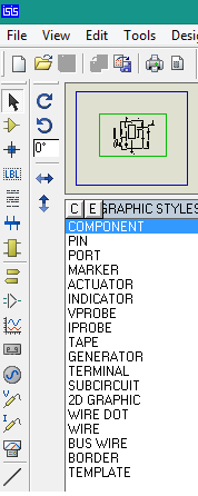
The historical project contains an interactive sensor symbol with a finger graphic and an OUT connection. Treat its interaction as a stimulus to the rest of the circuit. The graphic is not evidence that Proteus is calculating the complete electric field, enclosure geometry and real finger capacitance.
Use the model and project files supplied with the original example, and check which model dependencies your Proteus installation requires. Availability and controls can differ between installations. Do not assume that every component shown in an old screenshot is present under the same name in every release.
When inspecting the model, first measure its output without the timer connected. Determine whether it behaves as a voltage source, a digital detection signal or another defined interface. That observation tells you how to connect it to the transistor stage.
The rest of this tutorial assumes a compatible low-voltage active-high detection output: a high detection signal turns on the NPN transistor. If your real sensor has an open-drain or active-low output, its interface needs a corresponding change.
Trace the Original Circuit
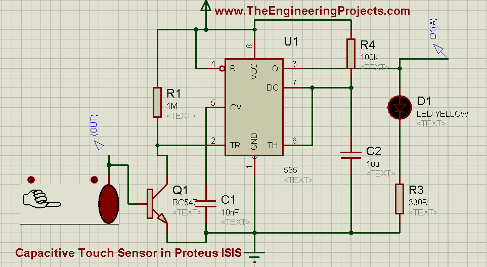
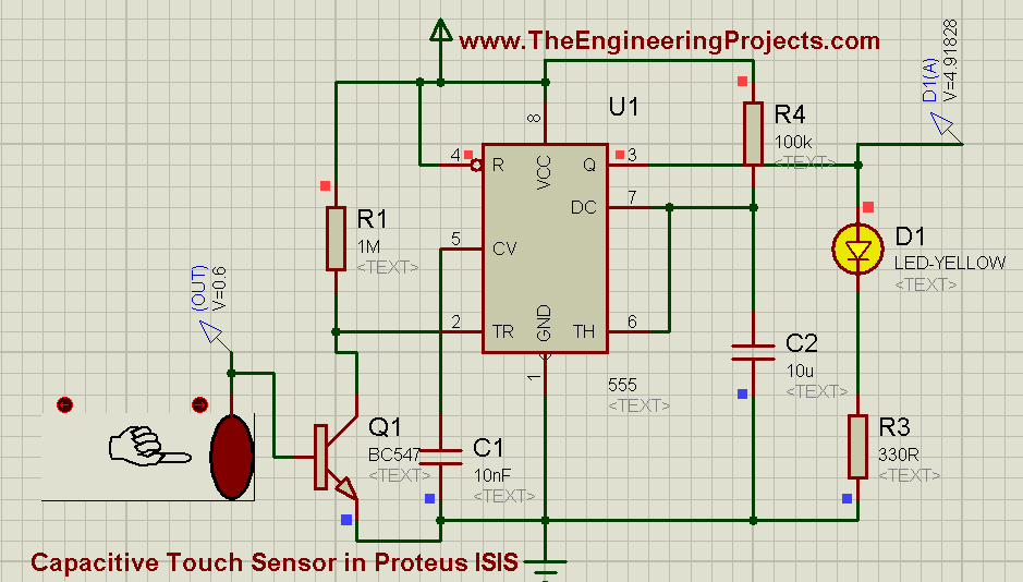
The sensor output feeds a BC547 transistor. The transistor emitter is grounded, and its collector pulls the 555 trigger input low when it conducts. The timer output drives an LED through a resistor.
The original drawing connects the sensor output directly to the transistor base. Add a suitable base resistor in a hardware interface so that the sensor output does not drive the base-emitter junction without defined current limiting.
The timing network uses 100 kΩ and 10 µF. The 555 threshold and discharge pins connect to that timing node, making it a monostable-style output stage. The sensor input determines when a trigger occurs; the timing network determines how the resulting pulse behaves.
For a different application of the same timer family, compare our 555 servo-control tutorial. The timer's configuration changes the function, so pulse-generator formulas must stay with the corresponding circuit.
Use a Defined Transistor Interface
For a 5 V demonstration with a compatible active-high sensor output, connect the output to the BC547 base through 10 kΩ. Add a 100 kΩ resistor from base to emitter, connect the emitter to ground, and connect the collector to trigger pin 2.
Pull pin 2 up to 5 V through 10 kΩ. When the transistor is off, the trigger is high. When the sensor drives the transistor on, the collector pulls the trigger low. All low-voltage sections need a common reference.
With an illustrative 5 V sensor high and 0.7 V base-emitter drop, base current through 10 kΩ is approximately 0.43 mA before the small pull-down current. The trigger pull-up requires roughly 0.5 mA when pulled low, so the interface uses the transistor as a modest signal switch.
Check the output-current capability of the actual sensor and the BC547 package pinout. A sensor output intended only for a high-impedance logic input may require a different interface. Do not assume that every module can source the same current.
Connect the 555 as a Monostable
- Connect pin 1 to ground and pin 8 to 5 V.
- Hold reset pin 4 high.
- Connect the transistor collector and trigger pull-up to pin 2.
- Join pins 6 and 7 at the timing node.
- Connect 100 kΩ from 5 V to the timing node.
- Connect 10 µF from the timing node to ground, observing polarity.
- Add a typical 10 nF control-pin capacitor from pin 5 to ground and local supply bypassing.
- Connect the output LED through its own current-limiting resistor.
The NE555 datasheet explains the trigger and threshold functions. At normal control voltage, trigger is associated with approximately one-third of the supply and threshold with approximately two-thirds.
At 5 V, those nominal levels are around 1.67 V and 3.33 V. The original statement that the timer triggers above a fixed 5 V threshold was incorrect. In this circuit, the transistor initiates the pulse by pulling the trigger low.
Calculate the Timed Output
For a brief valid trigger with the capacitor initially discharged, the nominal monostable duration is t ≈ 1.1RC. With 100 kΩ and 10 µF, the result is approximately 1.1 s.
The timing capacitor charges toward the supply until its voltage reaches the threshold. The output then returns low and the discharge path resets the capacitor for another cycle. Resistor and capacitor tolerance mean the measured duration need not be exactly 1.100 s.
Changing the timing capacitor to 4.7 µF gives a nominal duration near 0.517 s with the same resistor. Changing it to 22 µF gives about 2.42 s. These calculations describe the timer output interval, not the sensor's touch sensitivity.
| Adjustment | Main effect |
|---|---|
| Sensor electrode or detection threshold | When a touch is recognized |
| Transistor interface components | How the sensor output produces a valid trigger |
| Monostable resistor and capacitor | Nominal output duration after a brief trigger |
| LED resistor | Indicator current and brightness |
A Held Touch Is Not a Brief Trigger
The standard duration calculation assumes the trigger returns high appropriately. If the sensor stays active and keeps pin 2 low, the timer's behavior is not simply “one fixed pulse regardless of the input.” A sustained low trigger can keep the output high beyond the nominal timing interval.
If the capacitor has already crossed the threshold while trigger remains low, releasing the trigger can end the output promptly. This is why a held touch and a short touch may produce different LED on-times even with unchanged timing components.
Test three cases separately: a brief touch, a touch longer than the nominal interval, and a second touch during an active interval. Record the trigger and output waveforms. Do not infer all three behaviors from one screenshot of a glowing LED.
If you require exactly one pulse per new touch, add a defined edge-detection and pulse-shaping function or a controller that implements that rule. If you want the LED to follow touch continuously, a timer may be unnecessary. Choose the behavior before choosing the interface.
Interpret the Historical Sensor Images
The original near-finger image shows the circuit responding as the sensor model output changes. The older explanation associated about 0.6 V with triggering. That is closer to a simplified transistor base-emitter conduction discussion than a universal capacitive-touch threshold.
A transistor's base-emitter voltage is not an exact fixed switch point either. Collector current, gain, temperature and the surrounding resistors determine whether its collector falls low enough to trigger the timer.
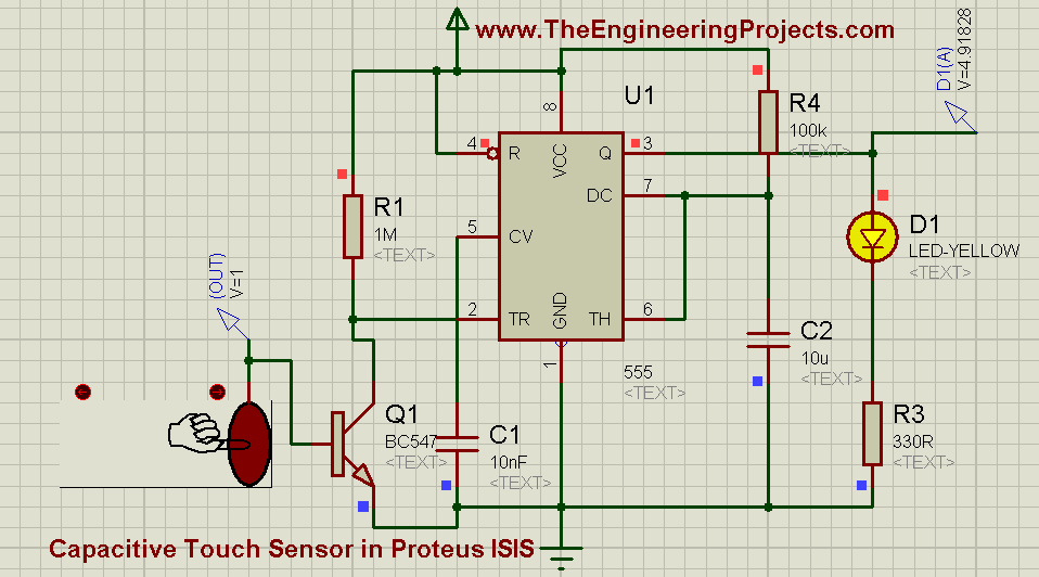
The closer-finger screenshot shows the output remaining near a high logic level. Once the timer output is high, moving the stimulus further does not necessarily increase LED voltage or brightness. The output stage has switched state; it is not directly reporting finger distance.
Also distinguish output voltage from the voltage across the LED itself. The LED and its series resistor share the output voltage. A measurement near 4.9 V at pin 3 is not automatically a 4.9 V LED forward drop.
Limit the LED Current
For an illustrative 5 V output and a 2 V LED drop, a 1 kΩ series resistor gives approximately 3 mA before allowing for the timer's output drop. This is a modest current for an indicator and reduces loading compared with a lower resistance.
The historical 330 Ω value would request approximately 9.1 mA under those idealized assumptions. It may be suitable for some LEDs, but calculate it from the actual device and output voltage rather than treating the resistor as arbitrary.
The timer's output need only drive the indicator in this project. A relay, motor or lamp requires an appropriate interface, and an inductive load needs suppression. Do not extend the circuit by substituting a high-current load for the LED.
Baseline, Threshold and Hysteresis in Real Sensors
A real touch controller must distinguish a touch from changes caused by temperature, humidity, wiring and nearby objects. It commonly maintains an untouched baseline and compares new measurements with that baseline.
For a simplified example, suppose an untouched measurement is 1000 counts and a touch raises it to 1120. The change is 120 counts. A detection threshold might be defined on that change rather than on the absolute raw reading.
Hysteresis uses different criteria for entering and leaving the touched state. For example, entering above an 80-count change and releasing below a 50-count change can prevent rapid toggling near one threshold. These numbers are illustrative, not settings for the supplied model.
Microchip's touch measurement operation guide discusses detection thresholds, integration and hysteresis. The 555 timing capacitor does not automatically provide those sensing algorithms.
Do not let calibration hide a real touch
Baseline tracking needs a deliberate policy. If a controller updates its baseline too quickly while a finger remains present, it can gradually treat the touched condition as normal. Conversely, a baseline that never adapts can become inaccurate as the environment changes.
Startup is another important test. Powering a sensor while a finger covers the electrode may give a different initial baseline from powering it untouched. A finished interface should define how it recovers and whether a maximum-touch timeout is appropriate for its purpose.
Record untouched measurements over time before choosing a detection threshold. Then compare repeated touches, releases and nearby non-touch movement. The useful margin is the separation between those conditions relative to noise and drift, not merely the largest signal observed during one favorable touch.
These are sensing-system tests. Changing the 555 output pulse duration can make the indicator easier to see, but it cannot repair an unreliable detection decision upstream.
Electrode and Enclosure Considerations
A larger electrode can increase coupling, but it also changes background capacitance and sensitivity to nearby objects. A thicker insulating cover generally changes the coupling geometry and may require a different electrode or threshold. There is no single finger-distance calibration for every installation.
Long sensor wires add capacitance and can collect interference. Nearby grounded metal, displays, power wiring and moisture can change the measurement. Evaluate the sensor in its final enclosure rather than only on an open desk.
Microchip's capacitive touch sensor design guide provides the relevant electrode and cover-design background. The animated model cannot validate immunity to water, electrostatic discharge or environmental interference.
Keep a real user-accessible electrode within an appropriately designed low-voltage sensing system. Do not turn this beginner demonstration into a direct connection to an unsafe external voltage. The intended function is capacitive detection through a controlled interface.
Download, Video and Test Procedure
The original project remains available below. It retains the historical direct-base connection; the revised interface and measurement recommendations have not been rebuilt into the archive.
The original video shows the interactive demonstration:
- Inspect the sensor model's output with the timer disconnected.
- Check the transistor base current and collector high/low levels.
- Apply a brief detection stimulus and measure the LED pulse.
- Hold the stimulus active longer than the nominal timer interval.
- Release it and observe recovery.
- Repeat near the detection boundary to look for chatter or repeated triggering.
Troubleshooting and Review
| Symptom | Check |
|---|---|
| No response to the model | Model output, transistor pinout, base resistor and trigger voltage |
| LED stays on | Sustained low trigger, timing-node wiring and capacitor state |
| Repeated unexpected pulses | Detection chatter, grounding, noise and trigger conditioning |
| Duration differs from calculation | Trigger duration, component values, tolerance and leakage |
| Hardware sensitivity differs from simulation | Electrode, enclosure, wiring, baseline and sensor implementation |
The important distinction is between detection and response. The sensor decides that its measured coupling has changed enough to count as touch; the transistor translates that decision; the timer shapes the response. Understanding each stage makes the complete circuit easier to adapt.
Frequently Asked Questions
Does a finger generate exactly 0.6 V?
No. Capacitive sensing detects changes in coupling. The transistor interface and model output determine the voltages in this circuit.
Is the 555 threshold fixed at 5 V?
No. With normal control voltage, its trigger and threshold levels are approximately one-third and two-thirds of the supply.
Does the timing capacitor set touch sensitivity?
It sets the timer's response duration. The sensor's measurement and detection process determine sensitivity.
Will a long touch always produce only a 1.1-second pulse?
Not with an indefinitely low trigger. Use appropriate edge conditioning if exactly one bounded pulse per touch is required.
Can the model prove that a real enclosure will work?
No. Real electrode geometry, noise, moisture and environmental behavior require testing with the actual sensor and enclosure.

Tags


hola para poder variar la distancia o digamos que se active a 1 milivolt como podria hacerlo gracias
Comments
4