


Design a Buzzer in Proteus ISIS


Hello friends! Today we will design and examine a buzzer circuit in Proteus ISIS. We will use a logic input, an optocoupler and a transistor to control a powered buzzer, then look at the changes needed before using the idea in hardware.
A buzzer is useful for indicating a timer event, a button press or a fault. The first design decision is whether the selected sounder contains its own oscillator or requires an alternating drive signal. Applying DC works for an active buzzer, but does not produce a continuous tone from every passive transducer.
The original simulation images remain in this tutorial. We will explain their active-low behavior while correcting several details that a simulation alone can hide, including LED current, transistor bias and optocoupler pin mapping.
Choose the Right Kind of Buzzer
An active buzzer, also called an indicator in many manufacturers' catalogs, includes a sound-generating circuit. Apply its rated DC supply and it produces a tone. A passive transducer requires an appropriate waveform from an external driver.
Magnetic and piezoelectric describe the sound-producing technology, while active and passive describe whether the driving oscillator is included. These are separate distinctions. A piezo device can be an active indicator or a passive transducer.
The manufacturer's CUI buzzer application note explains these categories and their different drive arrangements. Select the voltage, current and drive method from the actual part's specifications rather than from the generic word “buzzer.”
| Device | Typical control requirement | Important check |
|---|---|---|
| Active DC buzzer | Switch its rated supply on and off | Supply polarity, operating voltage and current |
| Passive piezo transducer | Apply an alternating waveform | Frequency, voltage swing and capacitive load |
| Passive magnetic transducer | Drive its coil with the specified waveform | Current and inductive switching behavior |
| Proteus sound model | Meet the model's electrical and audio conditions | Model properties and simulation audio settings |
Select the Components in Proteus
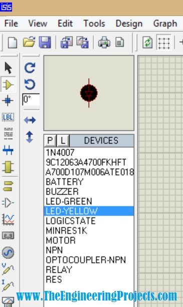
Start with a buzzer model, an NPN transistor, an optocoupler, resistors, an indicator LED, a DC source, a logic input and ground references. Search your installed library and inspect the properties of the selected parts. Model names and available features can differ between Proteus editions and versions.
If you are new to placing and connecting components, our Proteus ISIS and ARES introduction covers the basic workflow. Here, the important goal is to understand which current path changes when the input changes.
Understand the Original Circuit
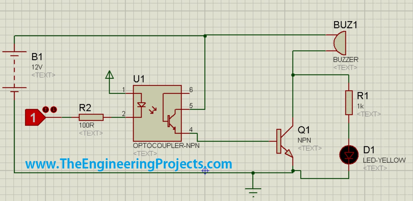
The original diagram uses a 12 V source for the buzzer. Q1 is a low-side NPN switch: its emitter connects to the supply return and its collector connects to the negative side of the buzzer. When Q1 conducts, current can flow through the buzzer to ground.
The optocoupler input LED is connected so that a low control signal sinks its current. The optocoupler then supplies drive to Q1. That is why the control is active-low: logic zero requests sound, while logic one releases the drive.
Active-low operation is a property of this connection, not an unavoidable property of every optocoupler. The input LED could be driven using another arrangement, and the output stage could introduce a different logic inversion.
| Control state in the historical circuit | Optocoupler input | Q1 | Intended buzzer state |
|---|---|---|---|
| LOW | Conducting | On | On |
| HIGH | Not conducting | Off | Off |
Do Not Copy the Generic Optocoupler Pin Numbers
The simulation drawing uses a generic six-pin optocoupler symbol, with an exposed transistor base connection. A PC817 normally has four pins and a different mapping. Substituting the real component therefore requires reconnecting by function, not matching the numbers shown on the generic symbol.
For the PC817 package covered by the Sharp datasheet, the functions are anode, cathode, emitter and collector on pins 1, 2, 3 and 4 respectively. Confirm the orientation and exact part drawing before wiring. Our PC817 introduction provides additional background.
The input LED needs a current-limiting resistor. The output transistor's available current depends on the input current and current-transfer ratio, abbreviated CTR. CTR varies with device grade, current and temperature, so a typical simulator value is not enough for a worst-case hardware design.
Calculate a Suitable Input Resistor
The original image labels the input resistor as 100 ohms. For a hypothetical 5 V control supply, a 1.2 V optocoupler LED drop and a 0.1 V low-level output, that would request approximately (5 − 1.2 − 0.1)/100 = 37 mA.
That is excessive for a routine Arduino GPIO drive design. Do not assume a digital logic symbol's ability to sink current means a real microcontroller pin can safely do the same.
For an illustrative input current around 5 mA, calculate:
Rinput = (Vlogic − VfLED − VOL) / IF
Using the same voltages and 680 ohms gives about 5.44 mA. Check the controller's guaranteed low-output voltage at the selected current, its total port limits and the optocoupler's LED limits before finalizing the value.
The resistor power is approximately I squared times R. At 5.44 mA through 680 ohms, this is about 0.020 W. Use an appropriate rating with margin, and repeat the calculation at the supply and component extremes relevant to the circuit.
Give Q1 a Defined and Limited Drive
The historical drawing connects the optocoupler output directly into the transistor base without showing a separate base-current-limiting resistor or base-to-emitter pull-down. A physical circuit should define both the on current and the off state.
For an illustrative active buzzer drawing 20 mA from 12 V, a conservative forced transistor gain of ten suggests about 2 mA of base current. The chosen transistor's saturation characteristics must support that operating point.
One possible arrangement places a resistor between 12 V and the optocoupler collector, with the optocoupler emitter feeding Q1's base. A 47-kilohm resistor between Q1 base and emitter provides an off-state discharge path. The exact resistor values depend on the optocoupler's guaranteed output current and available voltage.
As a first estimate, a 4.7-kilohm series drive resistor with approximately 0.2 V across the conducting optocoupler and 0.8 V across Q1's base-emitter junction allows (12 − 0.2 − 0.8)/4700, or about 2.34 mA. The pull-down takes a small part of that current.
At an assumed minimum CTR of 50%, a 5.44 mA optocoupler input could support about 2.72 mA collector current under the specified CTR test conditions. Check the actual datasheet conditions and margins; this calculation is an illustrative design path, not a universal guarantee for every PC817 grade and temperature.
If the load current is much higher, choose a suitable driver stage instead of increasing GPIO current indefinitely. A logic-level MOSFET or a dedicated driver can be appropriate, but its gate drive, ratings and off-state behavior also need to be defined.
Correct the Indicator LED Arrangement
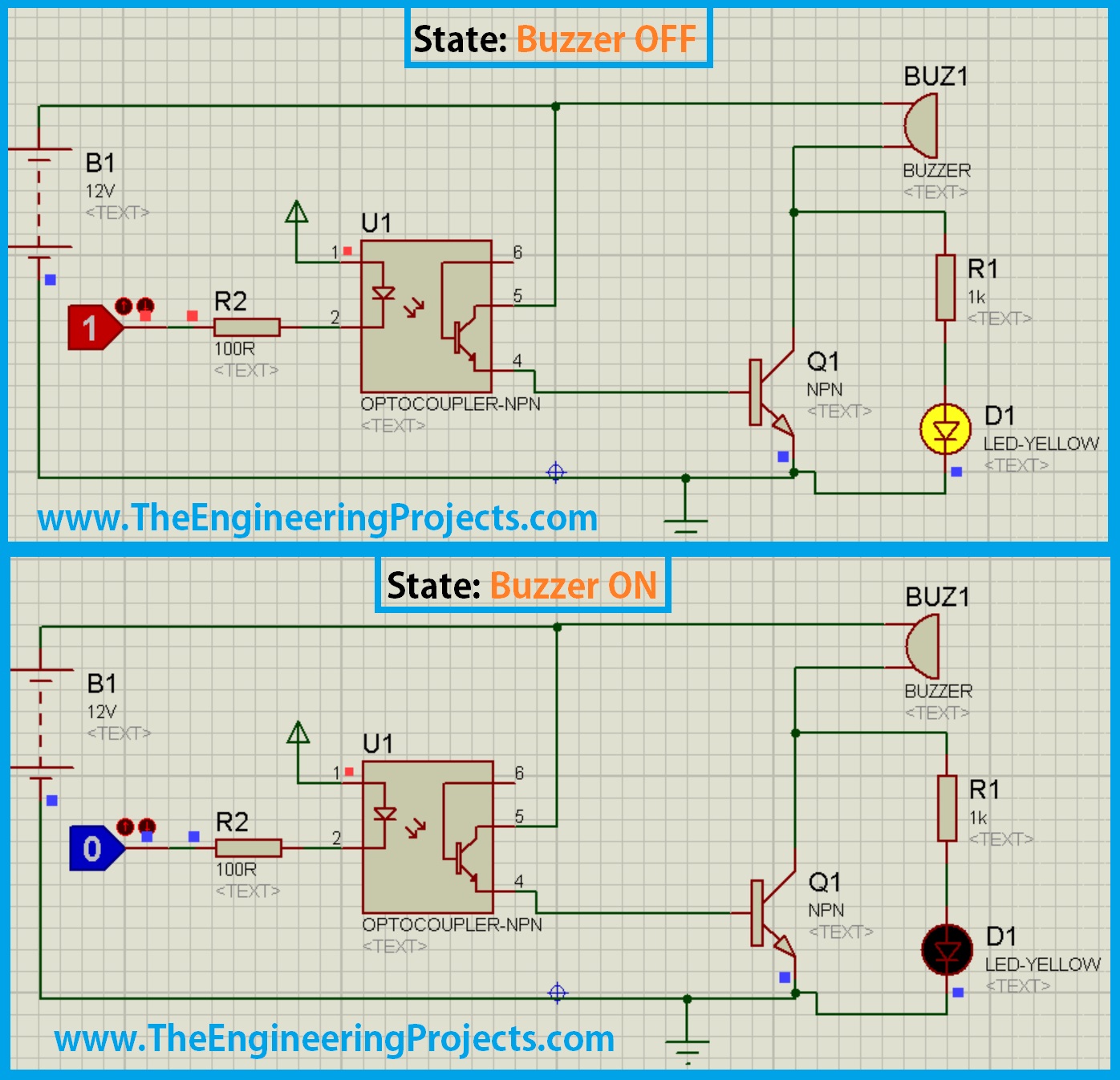
In the historical circuit, R1 and the yellow LED connect from Q1's collector to ground. When Q1 turns on, its collector is pulled low and the LED loses its forward voltage. When Q1 is off, current can reach that LED through the buzzer branch.
This explains the inverse indication in the screenshots, but also creates an unwanted current path through the buzzer while it is supposed to be off. A real active buzzer may click, sound weakly or behave unpredictably at that partial supply condition.
For a straightforward “buzzer on” indicator, place an LED and its own series resistor across the buzzer supply terminals, with the LED anode toward 12 V and its cathode toward Q1's collector. Then both the indicator and buzzer receive voltage when Q1 conducts.
For a 2 V indicator LED and roughly 5 mA desired current, a 2-kilohm calculation follows from (12 − 2)/0.005. A 2.2-kilohm resistor gives a slightly lower current. Include that indicator current in the transistor's total load calculation.
Run the Simulation and Inspect Both States
The retained composite image shows the historical circuit's two states: logic one leaves the buzzer off and its inverse indicator on, while logic zero activates the buzzer and extinguishes that indicator. The revised indicator arrangement described above intentionally changes the LED behavior.
- Check the source voltage and ground reference.
- Confirm the input LED polarity and resistor value.
- Start with the control in its intended off state.
- Run the simulation and observe Q1's collector voltage.
- Change the logic input and observe the voltage across the buzzer.
- Check current through the input LED and transistor.
- Compare the measured electrical states with the expected truth table.
For a low-side switch, the collector should move near the supply voltage in the off state when the load provides that path, and near the return potential in the on state. The buzzer voltage is the difference between its two terminals, not simply the collector voltage relative to ground.
If no sound is heard, inspect the electrical behavior first. Then check whether the selected model supports audible output, whether the simulation audio is enabled and whether the computer's audio device is muted. A static screenshot cannot demonstrate sound pressure or tone quality.
What Changes in Hardware?
Use a buzzer rated for the actual supply and check its current, including startup behavior. Select Q1 for the required voltage, current and dissipation. For a 20 mA load and a 0.2 V saturated drop, its conduction loss would be about 4 mW, but that example does not cover switching transients or a different load.
A magnetic load can produce inductive turn-off voltage. Follow the sounder's recommended drive circuit, using an appropriate clamp where required. A piezo transducer behaves primarily as a capacitive load and does not automatically need the same flyback arrangement as a relay coil.
An optocoupler can separate the input and output electrical circuits, but only when the supplies and wiring preserve that separation. Connecting both grounds elsewhere removes galvanic isolation. Component isolation ratings also do not certify an entire PCB or make an unspecified mains circuit suitable.
For this tutorial, use a low-voltage supply and an appropriate buzzer. The simulation is a way to understand switching behavior; it is not a substitute for checking the selected physical components and their current paths.
Adding a Microcontroller Later
A microcontroller can replace the logic input after you account for signal voltage, polarity and current. Our microcontroller introduction and Arduino projects provide related examples.
For active-low control, initialize the output latch high before switching the pin into output mode. Add suitable hardware bias so the load remains in its intended state while the controller resets or its pin is high impedance. Software initialization does not control the pin during the entire power-up interval.
An active buzzer can be beeped by switching its supply at a slow pattern, such as a short on interval followed by a longer off interval. A passive transducer instead needs an audio-frequency drive, which may be generated by a timer. Keep the beep pattern and audio carrier conceptually separate.
Check the Complete Load After Adding an Indicator
If the buzzer takes 20 mA and the parallel indicator takes another 4.5 mA, Q1 must switch roughly 24.5 mA. Under the earlier forced-gain assumption of ten, that calls for about 2.45 mA of base drive, so the illustrative 4.7-kilohm drive resistor needs to be reconsidered. This is why a small addition should trigger a recalculation of the whole branch.
Also test the intended off state with the input disconnected and with the control supply removed while the buzzer supply remains present. The load should not depend on a simulator's default logic value to remain off. Add the appropriate input and transistor bias for the real startup conditions.
Finally, acoustic performance cannot be inferred from voltage alone. The tone, mounting surface, enclosure opening and listening distance affect the result. A simulator beep demonstrates its audio feature; it is not a measurement of the physical buzzer's loudness or suitability for a particular environment.
Troubleshooting and FAQs
| Problem | Check first |
|---|---|
| No sound and no load voltage | Control polarity, optocoupler current and Q1 drive |
| Correct DC voltage but only a click | Whether the selected device is passive |
| Weak sound while off | Leakage paths, including the historical inverse LED branch |
| Controller pin draws too much current | Input resistor and supply voltage |
| Physical PC817 does not match the drawing | Four-pin package mapping versus the generic six-pin symbol |
| Unexpected beep at reset | Undefined startup input or transistor bias |
Is the optocoupler essential?
No. A suitable transistor driver can control a low-voltage buzzer directly from compatible logic. Use an optocoupler when its separation or interface behavior is part of the design requirement.
Why does logic zero turn this circuit on?
The input is wired to sink optocoupler LED current when low. It is an active-low connection, not a universal buzzer rule.
Can I connect a 12 V buzzer directly to an Arduino pin?
No. Use an appropriate driver and supply. The controller provides a control signal, not the buzzer's 12 V power.
What should I retain from this project?
Follow the current path in both states, calculate the input and driver currents, and keep every off state defined. Those habits transfer directly to relays, indicators and other small output devices in an embedded system.

Tags


the simulation isnt working with me
1 reply
Check all the connections and try. Its perfectly working for me.
1 reply
Hi man can you help me with a project
simulation is not working
1 reply
It's working perfectly bro, I think you need to check your computer sounds.
Comments
6