Hello Mentees! Welcome to the board. We hope you are doing great. We are working on another interesting yet easy Project in the Proteus ISIS and that is Digital Counter using 4026 IC in the Proteus. Counters are used in thousands of electronic experiments as well as in our daily life. Who is not5 familiar with Digital Watches and calculators. At the same token, the counters are used in the digital display microwave ovens and many household appliances as well.
In this session you will find the answers to the following questions:
What is 4026 IC?
What are Digital counters using 4026 IC?
How does Digital Counter using 4026 IC works?
How does we design the circuit of the Digital Counter circuit using 4026 IC in Proteus ISIS?
How can you convert this Circuit from 1 digit counter to many Digit Counter using 4026 IC?
In addition, you will also have some interesting chunks of information about the topic in DID YOU KNOW sections.
What is 4026 IC in Digital Counters
Integrated Circuits play a vital role in the field of circuits and electronics. These are the combination of different fundamental devices in very specific yet functional ways. The 4026 belongs to the family of the Integrated Circuits in the series of 4000. The 4026 IC is introduced as:
"The 4026 is CMOS seven Segment counter integrated Circuit that is the designed in decade Based and counts in the decimal digits and consist of total 16 pins."
The output of the 4026 digital counter is usually fed into a 7 segment display Light Emitting Diode that shows the counter output of the 4026 IC Counter.
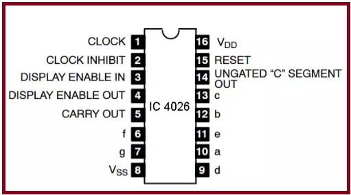
Being an IC, the pins of the 4026 Digital counter IC are very specific. By looking at the block diagram of 4026 IC Counter, we can generate a table that shows us the proper configuration of the 4026 IC.
Pin Number
Pin Name
Description of the Pin
1
Clock (CLK)
With each positive clock Pulse, it increments the counter.
2
CI (Clock Inhibit)
It is the Active high. When high, the counter freezes. When low, the clock pulse increments 7 segments.
3
DE (Display Enable)
Chip will ON when this is high and vise versa.
4
DEO (Display Enable Out)
Chaining 4026s.
5
CO (Carry Out)
It completes a single cycle after every 10 clock input cycles. It is used to change the clock manner of 1 counter into a multi counter.
6
F
This Pin is connected to ‘f’ of the 7 segment.
7
G
This pin is connected to ‘g’ of the 7 segment.
8
VSS
It is the Ground PIN
9
D
It is Connected to ‘d’ of the 7 segment.
10
A
It connects with the ‘a’ Pin of the 7 segment.
11
E
It Connects the ‘e’ of the 7 segment with it.
12
B
It Connects to the ‘b’ of the 7 segment.
13
C
It is Connected to ‘c’ of the 7 segment.
14
UCS ( Un-gated C-Segment)
It is an output for the seven-segment's C input that is not affected by the input of DE . When the count is 2, it is high.
15
RST (Reset)
Reset the counter to 0 when HIGH. Hence it is Active High.
16
VDD
Power supply PIN
In out experiment, we'll set all these pins according to our requirements to get the desired output. but some of the points here are pending to discuss. You may noticed the functioning of 6, 7, 9 to 13 pins of 4026 IC Counter. Let's have a look what does we mean by the description.
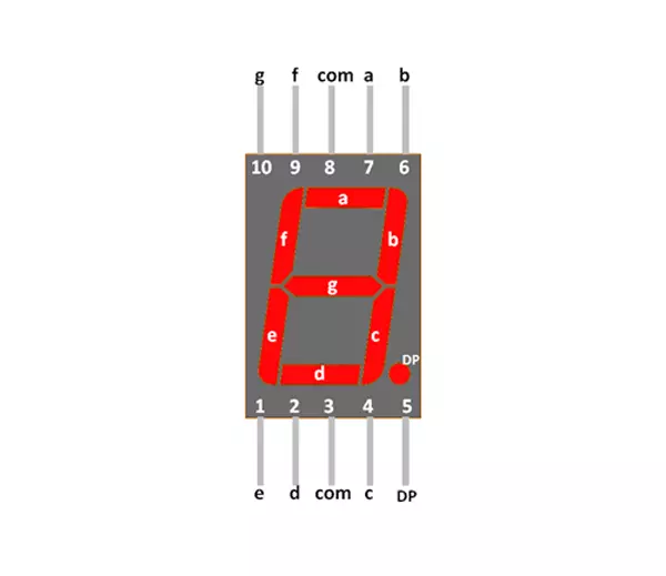
Seven Segment Display with 4026 IC Counter
This is the electronic device that is used to show the output of the counters such as 4026 IC. We define the Seven Segment Display as:
"The Seven Segment Display is a collection of 8 Light Emitting Diodes in a rectangular fashion that is an output device used to display the outcomes of different counters."
For the convenience of connections, each LED of the Seven Segment Display is named i alphabetically and hence each pin of Seven Segment Display is connected with pins of 4026 IC Counter.
Working of 4026 IC Digital Counter
The Simulation of the circuit starts with the pulse generation at the Clock Pulse. These Pulses enters the BC547 MOSFET that regulates the pulses.
The LED Connected to the BC547 MOSFET blink and we get the idea about the speed of the Pulse Generation.
The Pulse enters the 4026 IC Counter and the counter Passes these pulses to the seven segment Display device.
Each pulse from the 4026 IC power ups the respected LED of the seven segment display in a specific manner that we always get the digit as a result.
The power is then Grounded connected to the seven segment display terminal.
The output can be reset to the initial state with the button. This button is connected to the reset terminal of 4026 IC.
DID YOU KNOW ???
"You may skip the part of MOSFET and LED in the circuit but in some cases, when the error of the pulse occure, it may be difficult to examine whether the Pulses speed is low or there is another issue with the circuit."
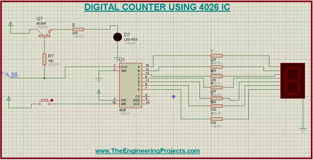
Circuit Design of Digital Counter using 4026 IC in Proteus
Fire up your Proteus Software.
Choose the first five devices given next from the Pick Library.
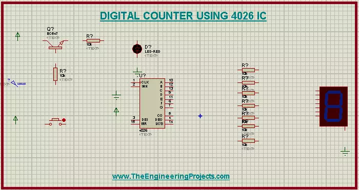
Material Required:
Seven Segment Cathod LED
Resistors
4026 IC Counter
MOSFET BC547
Button
Clock Pulse
Led
Ground Terminal
Power Terminal
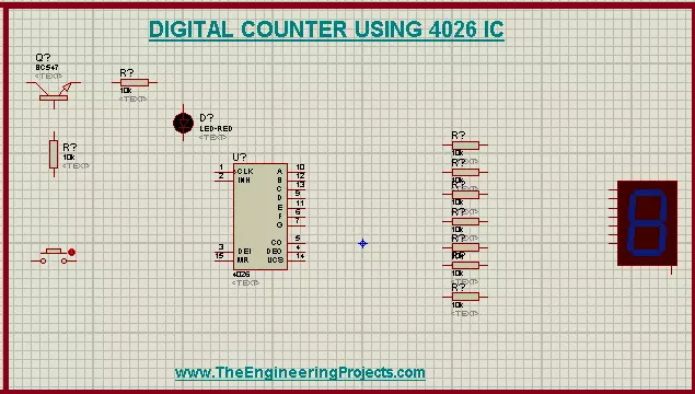
Arrange the material taken from the Pick Library at the working screen with the help of following image:
Go to generation mode and choose "Clock Pulse" then arrange it just after the left most resistor at the screen.
Go to Terminal Mode and get "Power" terminal. You will use three Power Terminals.
Attach power Terminal with pin 3 of 4026 IC Counter, with the MOSFET.
Get a ground terminal from terminal mode and attach it with the lower pin of seven segment display.
Repeat the above step for the pin 2 of the 4026 IC Counter.
Tip of circuit
"Why don't you try different colors of the seven Segment Display from the Proteus Pick Library of your choice?You have to change the names of the components by double clicking it and changing the label because Proteus does not recognize the components with the same names and through an error."
Change the values of the Components by double tapping them with the cursor.
Component
Value
Resistor 1 to 8
220 Ohms
Resistor 9
10k
Frequency of Clock Pulse
1 Hz
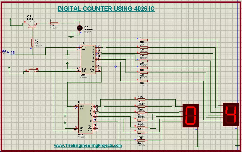
Connect all the components with the help of connecting wires. Be careful with connection and follow the image below:
Hit the play button to simulate the circuit.
Two Digit Counter using 4026 IC
If you want to make a two Digit counter, simply select the 4026 IC and Seven Segment Display>left click>click "block copy".
Paste this block at the screen.
Manage both the Seven Segment Displays side by side.
Change the names of the Resistors and 4026 IC to resist the duplication.
Connect the Pin 5 of 1st 4026 IC with the Pin 1 of the 2nd 4026 IC.
Connect Pin 15 of 2nd 4026 IC with the button given above.
Pop the Play button again and observe the result.
Result
When the Frequency of the Clock Pulse is 1. The Digital counter 4026 IC shows us the value from zero to one in normal speed.
Clicking the button resets the 4026 IC Digital Counter to the initial value, i.e, zero and starts the cycle.
Changing the value of clock pulse to 10 will increase the digits changing the speed of the seven segment Display output.
In two digits 4024 IC Counter, we can count the values till 99.
One can make the 3, 4 and so on digit counter using the same method.
Consequently, we learned an Interesting Circuit today, we saw what are the 4026 IC counter and with the combination of Seven Segment display and Transistor , how can we design a Digital counter circuit in the Proteus. Stay connected for other interesting circuits on The Engineering Projects.